

Page 1
Proudly
Sold
and
Serviced
by:
r
Healthrare
16
Redland
Drive,
Mitcham
VIG
3132
350
353
{ln
all
http://wwwparkarhealth,com.au
states)
+,
Replacement
°°
Parts
List
Ph:
(08)
8872
E-mail
iaulperkerhealth.com.ou
0222.
Fax:
1800
Website:
and
ATOM
Service
Model
TRANSPORT
Printed
Manual
V-801r
INCUBATOR
in
Sep.
1999
|
ATOM
MEDICAL
3-18-15,
Hongo,
CORPORATION
Bunkyo-ku,
Tokyo,
Japan.
Page 2
CONTENTS
—S
23
General:
[1]
Accessories
[2]
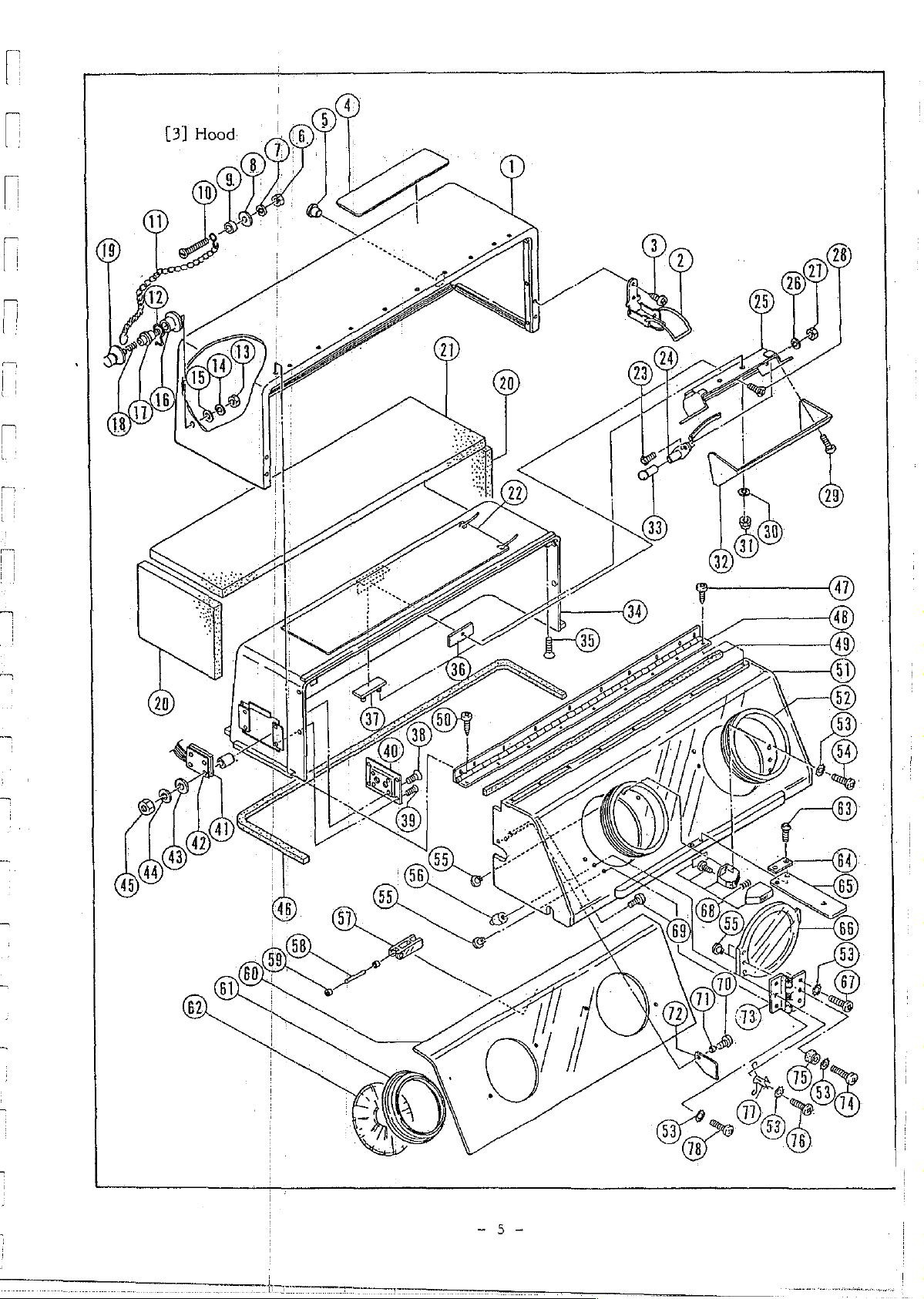
Hood
[3]
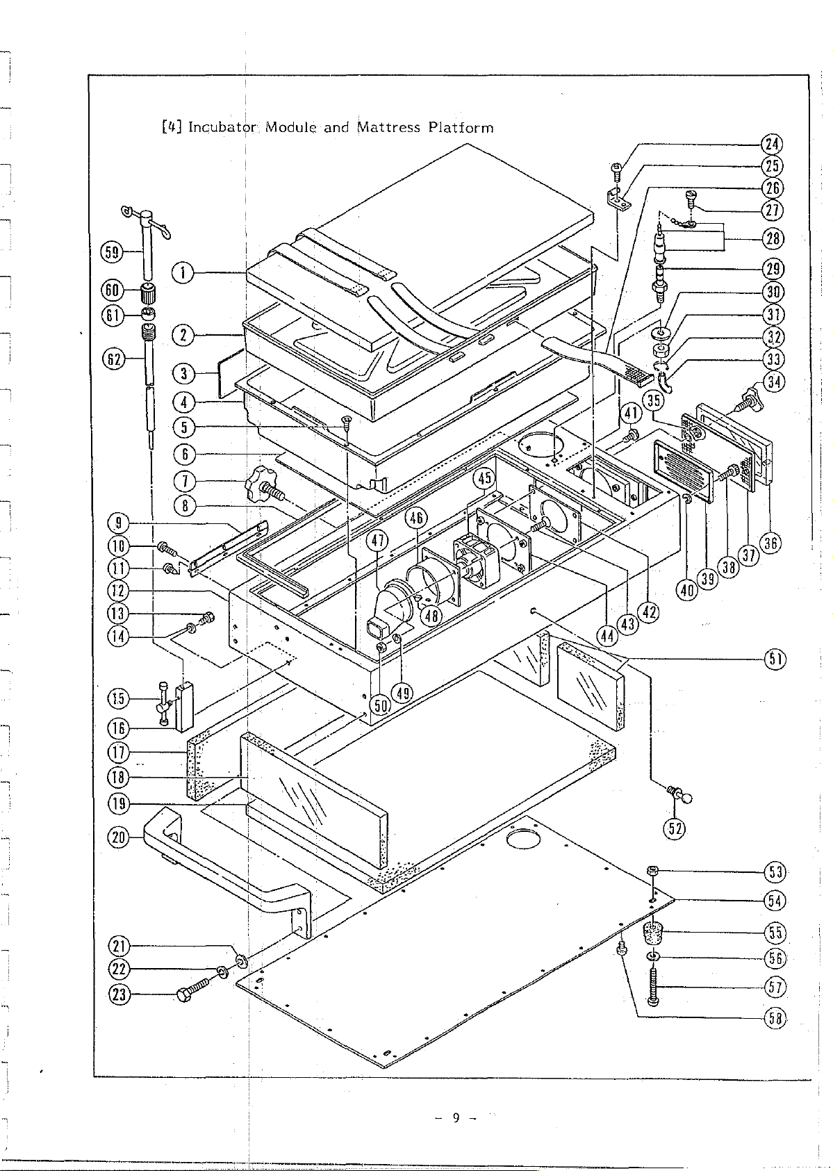
[4]
Incubator
Power
[5]
General
[6]
Battery
[7]
Battery
[8]
View
|
Unit
View
‘Unit
and
[Transport
Sener
ose
urnes
Module
[Power
sersem
and
Conponents
and
Mattress
Pack]
Power
SERVICE
Incubator]
eee
tee
Platforrnm
ト
・・・
Pack
+-.................s.
eee
+
MANUAL
++
encase
トバ
ei
++..........
«+++
・・・・・・・・・・ーーー・
トト
トト
と
ます
まま
トート
ます
ーーー
O
,。
1
3
の
5
9
12
15
17
19
CS
=
=
Page 3
ーーー
TT
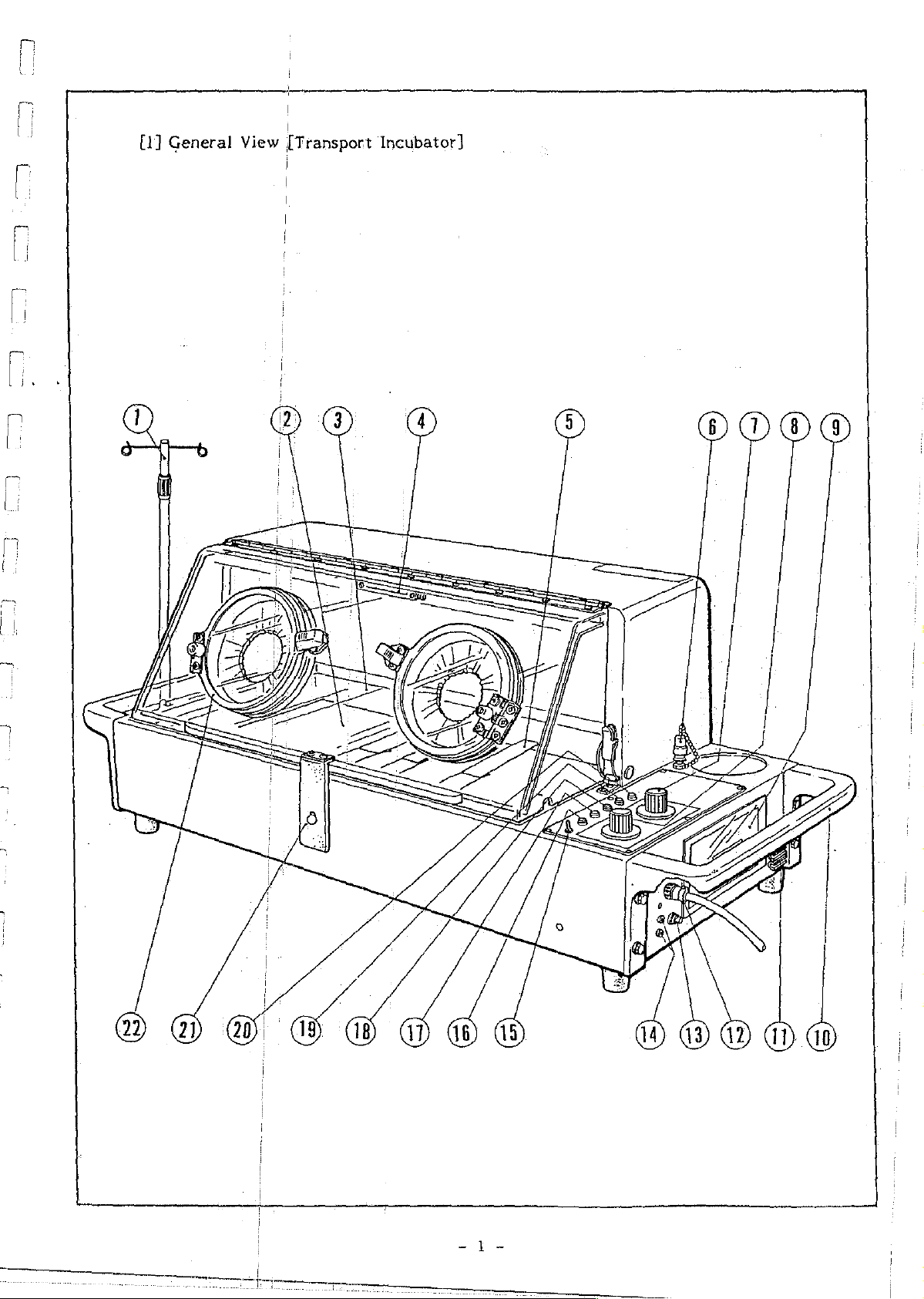
[1]
General
View
|
[Transport
Incubator]
ea
eso
Page 4
1
i
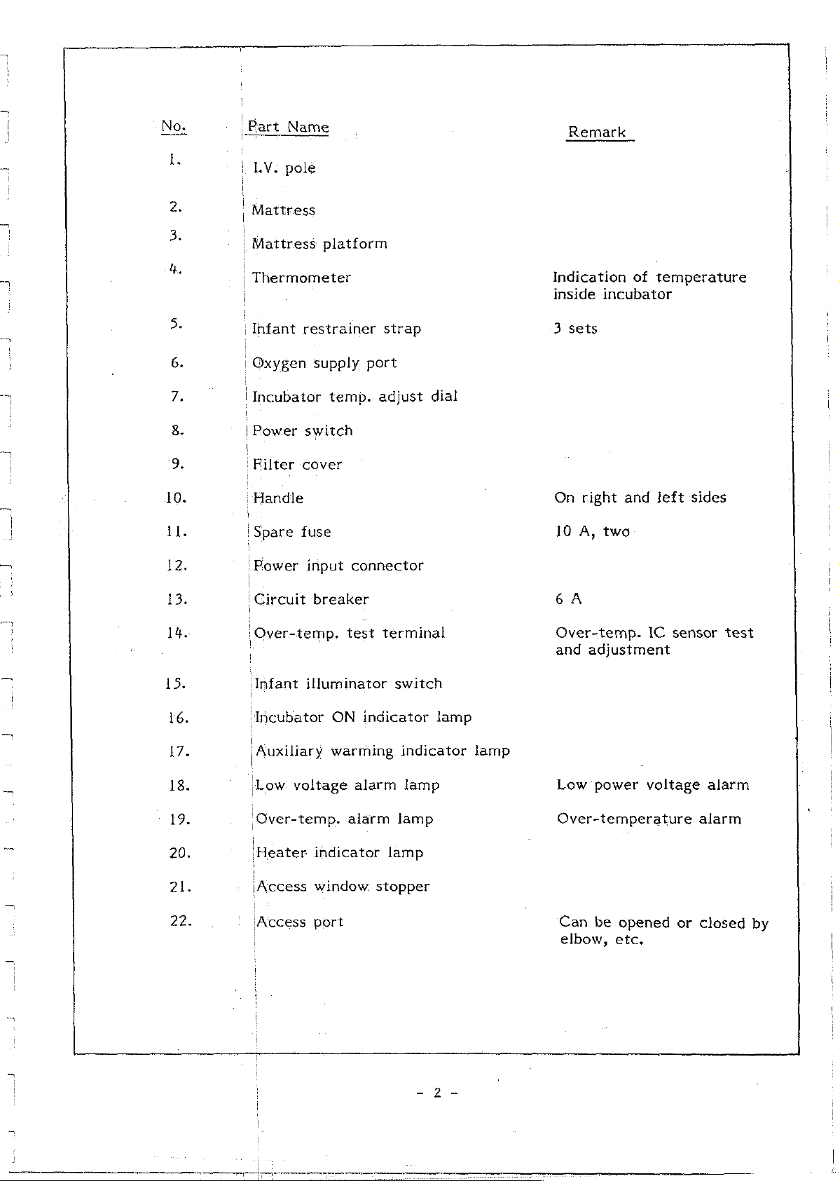
Part
|
LV.
|
Mattress
1
|
Mattress
Name
pole
platform
Remark
10.
11.
12.
13.
14.
15.
|
Thermometer
i
Infant
|
Oxygen
‘Incubator
|
Power
|
i
Filter
|
Handle
{Spare
„Power
|
Circuit
¡Over-temp.
(Infant
restrainer
supply
switch
cover
fuse
input
breaker
illuminator
port
temp.
adjust
connector
test
strap
dial
terminal
switch
Indication
inside
3
On
10
6A
Over-temp.
and
incubator
sets
right
À,
two
adjustment
of
temperature
and
left
IC
sides
sensor
test
16.
17.
18.
19.
20.
21.
22.
‘Incubator
Auxiliary
Low
voltage
‘Over-temp.
‘Heater
¡Access
¡Access
ON
indicator
warming.
alarm
alarm
indicator
window
port
indicator
lamp
lamp
lamp
stopper
lamp
lamp
Low
power
Over-temperature
Can
be
elbow,
voltage
opened
etc.
or
alarm
alarm
closed
by
Page 5
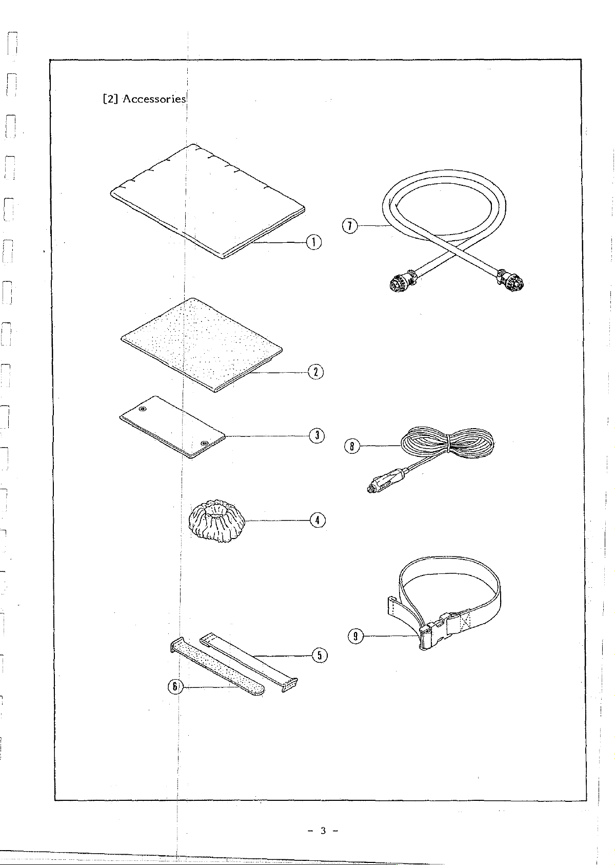
[2]
Accessories!
Page 6

Part
Part
Name
No,
二
-一
一
-
Dust
cover
Humidifying
Filter
Access
Infant
Infant
Connecting
Car
Body
element
port
restrainer
restrainer
plug
restrainer
sponge
cover
cord
strap
(L)
(semi-iris)
strap
strap
(male)
(female)
803 - 1001
803 - 1002
803 - 1003
803 - 1004
803 - 1005
803 - 1006
803 - 1007
803 - 1009
803 - 1010
a:
Page 7
一
TI
CI TY
DI
wed
Page 8
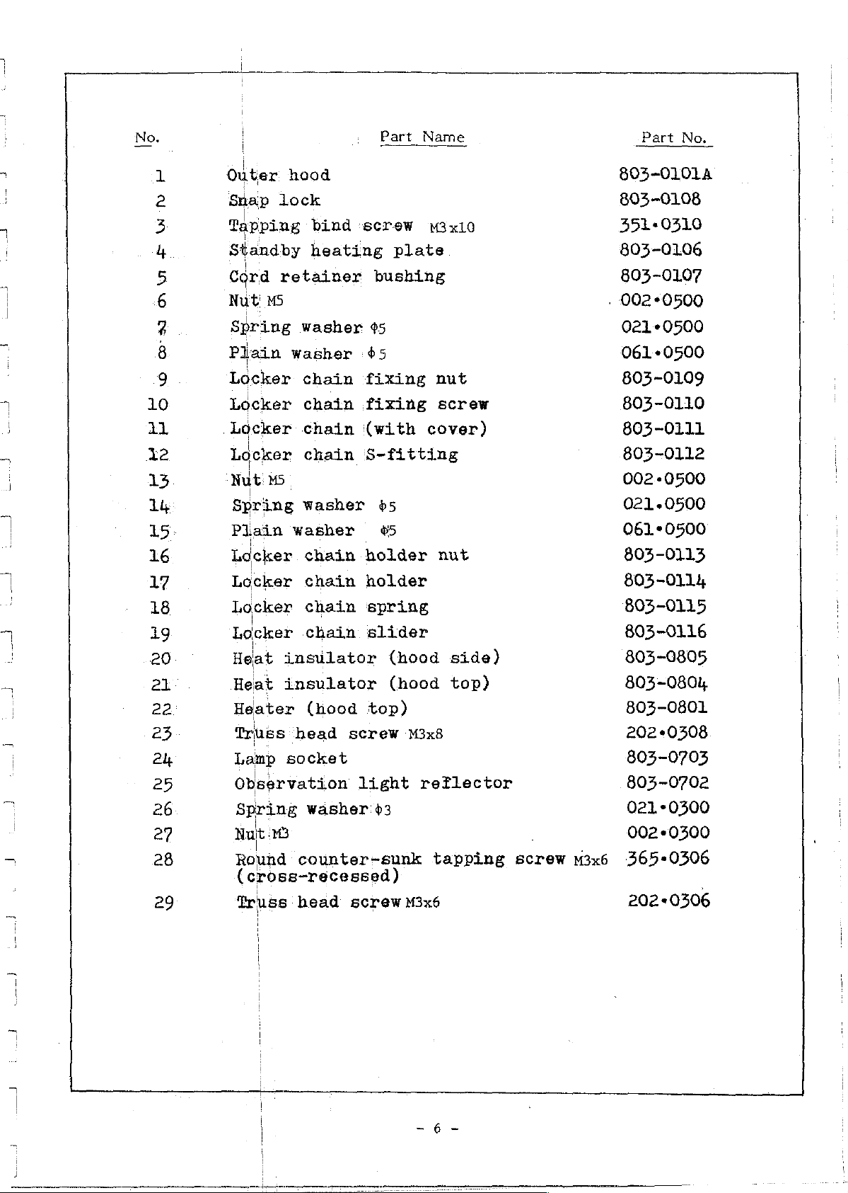
Part
Name
Part
No.
已
Wh
fF
ny
oN
D
HEE
FP
HE
EF
Outer
Snap
Tapping
Standby
Cord
Nut
Spring
Plain
Locker
Locker
Locker
Locker
Nut
Spring
Plain
Locker
hood
lock
retainer
15
washer
M5
washer
bind
heating
washer
chain
chain
chain
chain
washer
chain
screw
fixing
fixing
(with
S-fitting
holder
plate
bushing
$5
65
65
#5
M3x10
nut
screw
cover)
nut
803-0101A
803-0108
351.0310
803-0106
803-0107
.
002-0500
021-0500
061-0500
803-0109
803-0110
803-0111
803-0112
002-0500
021.0500
061-0500
803-0113
Locker
Locker
фозамеяюно
ме
WWW
BARER
№
NO
Locker
Heat
chain
chain
chain
insulator
Heat
Heater
Truss
Lamp
Observation
Spring
Nut
Round
(cross-recessed)
Truss
insulator
(nood
head
socket
washer'3
65
counter-sunk
head
screw
light
screw
holder
spring
slider
(hood
(hood
top)
M3x8
M3x6
side)
top)
reflector
tapping
screw
M3x6
803-0114
803-0115
803-0116
803-0805
803-0801,
803-0801
202
«0308
803-0703
803-0702
0210300
002+0300
365-0306
202-0506
Page 9
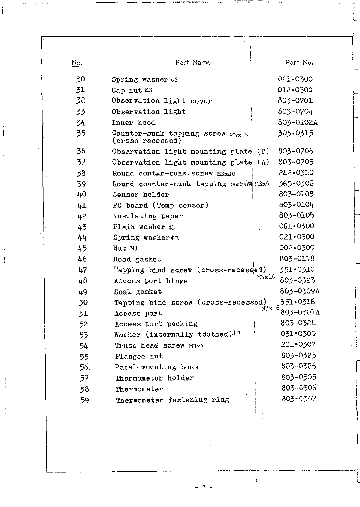
Part
Name
Part
No.
30
31
32
33
34
35
36
37
38
39
40
ul
42
43
hh
45
46
47
48
Spring
Cap
Observation
Observation
Inner
Counter-sunk
(cross-recessed)
Observation
Observation
Round
Round.
Sensor
PC
Insulating
Plain
Spring
Nut
Hood
Tapping
Access
washer
nut
M3
hood
conter~sunk
counter-sunk
holder
board
washer
washer
.M3
gasket
port
light
light
light
light
(Temp
paper
43
bind
hinge
è3
cover
tapping
mounting
mounting
screw
sensor)
63
screw
screw
tapping
(cross-receseed)
M3x15
plate
plate
M3x10
screw
|
(B)
(A)
M3x6
|
M3x10
021
+0300
012-0300
803-0701
803-0704
803-0102A
305-0315
803-0706
803-0705
242+0310
365-0506
803-0103
803-0104
803-0105
061-0300
0210200
002-0300
803-0118
351+0310
803-0323
49
50
51
52
53
54
55
56
57
58
59
Seal
Tapping
Access
Access
Washer
Truss
Flanged
Panel
Thermometer
Thermometer
Thermometer
gasket
port
port
(internally
head
mounting
bind
nut
screw
packing
screw
boss
holder
fastening
(cross-recessed)
toothed)03
M3x7
ring
i
i
i
M3x1
803-0309A
351-0316
805-0501А
803-0324
031°0300
201・0307
803-0325
803-0326
803-0305
803-0306
803-0307
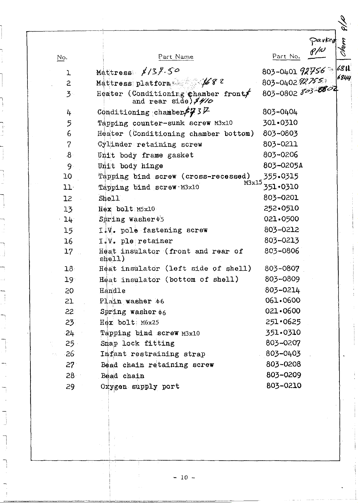
Page 10
Part
No.
Bart
Name
No.
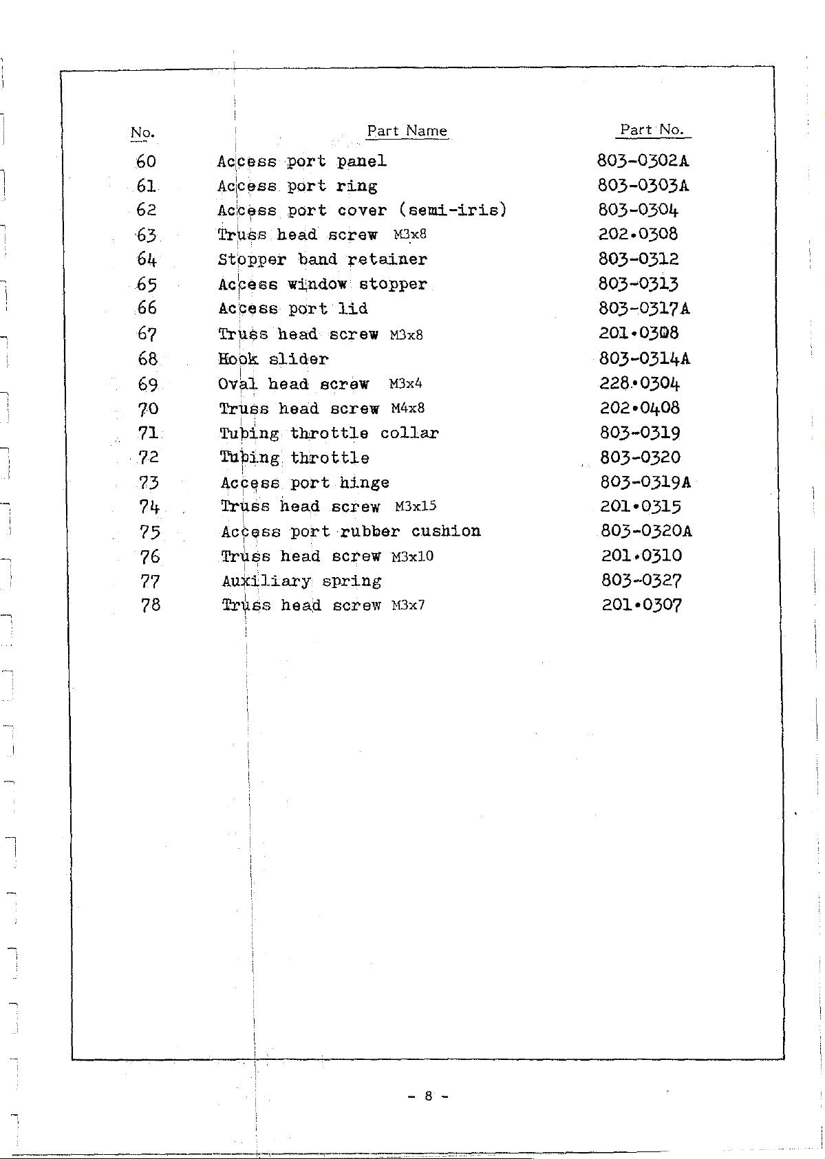
60
61
62
63
64
65
66
67
68
69
70
71
72
73
74
25
76
77
78
Access
Access
Access
Truss
Stopper
Access
Access.
Truss
Hook
Oval
Truss
Tubing:
Tubing
Access
Truss
Access
Truss
Auxiliary
Truss
head
head
slider
head
head
head
head
head
port
port
port
window
port
throttle
throttle
port
port
band
panel
ring
cover
screw
retainer
lid
screw
screw
screw
hinge
screw
rubber
screw
spring
screw
(semi-iris)
M3x8
stopper
M3x8
M3x4
M4x8
collar
M3x15
cushion
M3x10
M3x7
805-0502А
803-03034
803-0304
202
+0308
803-0312
803~0313
803-0317A
201-0308
803-0314A
228-0304
202+0408
803-0319
803-0320
803-0319
201-0315
803-03204
201-0310
803-0327
201-0307
Page 11
Page 12
Part
Part
Name
No.
юн
*£
au
OO
о
ピピ
RO
ピロ
ピロ
ピピ
ビビ
ワ
SAGEM»
18
Mattress’
Mattress
Heater
Conditioning
Tapping
Heater
Cylinder
Unit
Unit
Tapping
Tapping
Shell
Hex
Spring
Liv.
TeV.
Heat
shell)
Heat
body
body
bolt
pole
ple
insulator
insulator
£/3?-
platform"
(Conditioning
and
counter-sunk
(Conditioning
retaining
frame
hinge
bind
bind
M5x10
washer
fastening
retainer
so
rear
side)
chamberP¥
gasket
screw
screw:
05
M3x10
(front
(left
SI
€hamber
##/©
37
screw
chamber
screw
(cross-recessed)
screw
and
side
fronty
M3x10
bottom)
rear
of
of
shell)
M3x15
803-0401
74756
803-0402755
805-0802
803-0404
3010310
803-0803
803-0211
803-0206
803-0205A
355.0315
3510310
803-0201
252+0510
021-0500
803-0212
803-0213
803-0806
803-0807
273-887
の
|
19
20
el
22
25
24
25
26
27
28
29
Heat
Handle
Plain
Spring
Hex
bolt:
Tapping
Snap
Infant
Bead
Bead
Oxygen
insulator
washer
Washer
M6x25
bind
lock
chain
chain
fitting
restraining
retaining
supply
(bottom
46
66
:screw
port
M3x10
strap
screw
of
shell)
803-0809
803-0214
061-0600
021-0600
25170625
351.0310
803-0207
803-0403
803-0208
803-0209
803-0210
~
10
-
Page 13

Part
Name
Part
No.
30
31
32
33
34
35
36
37
38
39
40
ul
42
43
iş
45
46
4?
48
49
50
51
52
53
54
55
56
57
58
59
60.
Plain
U-nut
TY-RAP
|
(Oxygen.
Filter
E-ring
Filter
Filter
Filter
Fan
cover
|
Bering
Truss.
Vibration
Counter-sunk
Fan
holder
Fan.
motor
Air
pipe
Air.
supply
TY-RAP
Spring
Nut
M3
‘Heat
Hook
Nut
M4
Bottom
Rubber
Plain
Round
Round
IsV.
i»
Clamping
washer
M8
connecting
cover
cover
element
cover
$4
head
washer
insulator
stopper
plate
cushion
washer
head
head
pole
98
screw
absorbing
joint
screw
screw
screw
mount
mount
screw
$3
(right
64
tube
screw
screw
M4x8
m4x25
M3x4
gasket
side
of
shell)
065+0800
085-0800
803-0215
803-0216
803-0605
101-0506
803-0602
803-0601
803-0604
803-0603
101*0400
202
«0408
803-0503
232-0335
803-0502A
803-0501A
803-0506
803-0504
803-0505
021・0300
002-0300
803-0808
803-0204.
002
«0400
803-0202
803-0203
061・0400
2220425
222
+0304
803-0217
803-0218
|
61
62
Clamping
I.V.
pole
screw
support
-
AI
803-0219
803-0220
-
Page 14

[5]
Power
Unit
-
12-
Page 15

у
(|Z
one
pus
GA
6B
6C
6D
GE
eF
|
|
Power
Toothed
Truss
Set
Incubator
Dial:
|
,
Dial
Plain
Spring
Dial
Dial
Dial:
Power
Set
Switch
head
screw
assembly
nut
washer
nut
retaining
body
screw
Part-Name
panel
lock
screw
.M3x3
temp.
washer
switch
'M3x3
assembly
washer
with
adjust
plate
$3
hex,
dial
hole
Part
No.
803 - 0901
031'-
803 - 0926
267 + 0303
803 - 0902
803 - 0903
803 - 0904
267 + 0303
803 - 0905
0300
10.
11.
12.
13.
14,
15.
9A
|
9B
96
|
LOA
10B
|
106
BA
136
136
13D
|
,
|
、
|
|
Switch
Plain
Switch
Indicator
Indicator
Nut
Toothed
Indicator
Indicator
liluminator
Switch
Plain
Switch
Switch
Connector
Connector
nut
washer
body
lock
nut
washer
nut
body
lamp
lamp
lamp
lamp
switch
10P
10P
(orange)
body
washer
(red)
(green)
assembly
(socket)
(plug)
assembly
assembly
assembly
803 - 0906
803 - 0907
803 - 0908
803 - 0909
803 - 0922
803 - 0923
16.
17.
18.
19.
Connector
Connector
Tiewrap
Connector
2P
(socket)
2P
(plug)
18?
-
13
803 - 0924
803 - 0925
803 - 0915
803 - 0913
=
Page 16

Part
Part
Name
No.
A
31A
31B
32.
33.
34.
35.
Connector
Bind
screw
Spring
Base
board
Base
Spring
Nut
M4
Relay
Bindiscrew
Spare
Spare
Buzzer
Buzzer
Buzzer
Nut
M3
Spring
Power
Circuit
washer
board
washer
fuse
fuse
assembly
mount
body
washer
input
breaker
:7P
M4x8
$4
mount
64
M4x8
for
car
holder
sponge
63
connector
boss
plug
assembly
803 - 0914
212 - 0408
021 + 0400
803 - 0911
803 - 0912
‘021 - 0400
002
803 - 0910
212 - 0408
803 - 0920
803 - 0921
803 - 0916
002 - 0300
021 - 0300
0400
803 - 0917
803 - 0918
36.
37.
35A
35B
35C
36A
36B
36C
Breaker
Adjust
Fastening.
Over-temp.
Nut
Plain
Over-temp.
Truss
body
nut
washer
head
nut
test
test
screw
terminal
terminal
M3x10
assembly
body
803 - 0919
202 - 0310
-
14
-
Page 17

[6]
Gener.
al
View
[Power
Pack]
-
15-
Page 18

10.
;
Charging
|
|
Power
.
Battery:
Power
|
Power
|
Output
|
'
Input
|
Auxiliary
|
Spare
|
Shoulder;
Part
Name
indicator
cord
check
switch
output.connector
fuse
fuse
fuse
strap
holder
holder
power
button
connector
Remark
DC
12
Y
8A
2A
DC
12
V
Two 2 A&
Two 8 A
Örü
-
16
-
bön
Page 19

[7]
Battery
Unit
and
Power
Panel
-
17-
Page 20

Part
Part
Name
No.
>
own
vu
NA
11.
12.
13.
14,
15.
15A
“Power
|
Power
|
Power
|
Power
|
Truss
Connector
¡Connector
¡Terminal
Spring
¡Oval
Power
Charging
Spring
Nur
Check
Check
cord
cord
cord
panel
head
washer
head
switch
washer
ws
button
button
retaining band
bushing
screw
10P
10P
screw
indicator
3x8
(socket)
(plug)
$ 3
M3x20
43
assembly
body
804 - 0206
804 - 0207
804 - 0208
804 - 0201
202 - 0308
804 - 0212
804 - 0213
804 - 0211
021 + 0300
222 . 0320
804 - 0205
804 - 0202
021 - 0300
002 - 0500
804 ~ 0204
16.
17.
18.
19.
20.
21.
I5B
15C
Spring
washer
Nut
Unit
body
Side
plate
Side
plate
Counter-sunk
Bottom
Truss
frame
head
frame
(A)
(B)
screw
mount
screw
gasket
M4x6
plate
M3x8
804 ~ 0104
804 - 0101
804 - 0102
231 - 0406
304 - 0103
201 - 0308
-
18
-
Page 21

(8]
Battery
and
Components
Page 22

Part
1А
Battery
Battery
Name
assembly
Part
804
-
No.
0301
t
ii
1B
mrk
ЕН?
Hex-head
Battery
Battery
Spring
Bind
screw.
Battery
Spring
Bind
Bind
Spring
Relay
Nut
Spring
Power
Truss.
Power
bolt
terminal
retaining
washer
M4xB
retaining
washer
screw
screw:
M3
headiscrew
washer
washer
outlet
out
fuse
M4x8
washer
rubber
$4
plate
6.4
M4x8
44
$3
receptacle
M3x10
holder
assembly
804
-
804
-
021
212:
804
-
021
212
212
-
021
804
002
021
804
202
804
0302
0303
+
0400
0408
0304
+
0400
+
0408
0408
-
0400
-
0310
-
0300
+
0300
-
03141
+
0310
-
0312
17.
16A
16B
16C
Nut
Plain’
Fuse
Power
washer
holder
out
body
fuse
804.
-
0313
Page 23

J
-下
-一
一
ば
ーー
O
”
WIRING
り
„
-{PCBL]
»
ELECTRICAL
h
CIRCUIT
ADJUSTMENT
Power
Power
NH
Illumination
|
ο
Service
СОТАСВАМ
DTIRAGRRM-
ο
PRINTED
DESCRIPTION
|Supply
Switch
CIRCUIT
PARTS
PROCEDURE
1"
Modes
Lamp
Manual
«ааа
ツー
ーー
BOARDS
LIST
AND
totter
ーー
ドド
Switch
o
ーー・
cine
이
還
steer
erenere
илиилиинини:
A
いい
の
rer,
tee
seen c nee
還
corona
еее
eens
coreana
ras
28
28
28
e
29
Constant-Voltage
B U
Temperature
の
Incubator
οσο
WYN
'
FH
7-2
7-3
8.
|
АЛакм:
Incubator
protection
overheating
Low-voltage
Troubleshooting
СЗ
1
1
сеет
に
Air
air
Circuiti
Ромек
Temperature
overtemperature
of
heater
alarm
o...
барр1у*
た に
した に にし と また
tttorioe
safety
Circuit
た と
Control
eee
人
*
ミミ
ミミ ミミ
Circuit
ee
00
0000000000000
thermostat
ミミ
ミサ
еее
++
すす ミミ
すす
cc
tt:
29
*
30
31
33
33
34
35
37
Page 24

POWER
GORD
AUXILIARY
POWER
[A
İN
+
FRAME
GND
.
DY
2)
=
TERMINAL
8
©
5
CNB2
GNB3
CNBtO
FRAME
r
GND
INPUT
FUSE
ONO
FH]
INPUT
FUSE
no
FH2
CNBI
GNBG
。
.
6
GNB4
CNB5
|
SWITCHING
REGULATOR
T----------------
i
!
i
!
AGQO-132V
1(A0180~264V)
|
i
+
4
i
LFG
!
0
一
一
1
;
i
i
i
|
г
1
1
İmama
-
#i2v
(oa
ov
mmm
i
i
{
!
:
|
|
|
!
i
}
レー
,
i
}
!
Primary
Second:
一
一
一
GNAS
并
0R7
;
POWER
OUTPUT
ро
L
XGNB---GONNEGTOR
TT
#CNA---GONNEGTOR
OUTPUT
FUSE
ONO
FH3
ー
ϐδΡ:
10P
77
(111111111
BATTERY
CHARGING
INDIGATOR
=
ATE
"
DO
CNBg
CNB7
-
TT
GNA2
ONA4
-
GNA3
CNAT
dd
VR]
p
KE
RB
|
35
>
o
8
)
|
|
|
|
7
Er
o
!
Page 25

V:807r
pen
FIXED
LIGHT
TRANSFORM
CONTROL
BASE
1234 5 67 8 910412131415161718
4
1
ーーーーーーーー1
すこ
i:
1
CAPSULE
HEATER
OVERHEAT
Low
VOLTAGE
RESERVE
KEEPING
WARMTH
ORYE
THERMOSTAT
24
YR
OVERHEAT
TEST
TERMINAL
©
© ©
INPUT
CONNECTOR
POWER
SW
Page 26

V-80TtR
POWER
INPUT
©
0-0
9
©
FIXED
LIGHT
LIGHT
mee
KEEPING
WARMTH
TRANSFORM
т
é 1
STANDBY
HEATING
INDICATEA]
CAPSULE
E10
DRIVE
CRIZINDICATER
O
THI
SAVING
DIAGRAM
ISTAT
OVERMEAT
1
Es
pi
A
RU
이
EI
—
25
[に
fo
SO)
©
OVEAMEAT
TERMINAL
e
Page 27

1
“og
vga
2
R23
ORG
R24
CR7
cui
|
so
5
ΕΠ
HE
0º
č
L
TT
L
VR2
cB
τοι
H-
一
ww
ㅡ
0
s
N
AM_
+
一
ww 一 R7
—M—
—M—
一
vw
=
8
MM
AM
<
a à m
as
a
È
R26
„A
<
“
고
3
o
FA
©
RS
м
RI
RIA
©
R16
ms
RIO
or
02
RM
12
I
9
5
ant
am
5
2”
Så
2
8
3
=
35
E
る
m
=
3
=
ом
IA
B
Des
MW
в
bi
一
Vw
AN
ea
ーー
sn
る
R25
94
cas
RI
R2 二
em
Ki 4
OX
3 2
O
A
cs
T
-
26
—
Page 28

V-
BOTR
FIX
ED
LIGHT
TRANSFORM
、
|
|
COMPONENT
Ai,
R11,
R25,
912,
R21,
R22,
R4,
R13
AZ
Ra
AZ, AB,
R16
nia
85,
814,
Ra,
ci
103
819
RIS.
DE Ts
cd,
013
C2.
C4,
C8, C7,
69.
CIO,
011,
CR2, GR3, CA4,
02,
03, 05,
04
ie1
162
104
169,
106
vR1
VAS,
VA4
VAB
VR2
YR6-
cna,
CRO
GRIO
cit,
GRIZ
GNA
GNA
CNB
ČNS
GNG
CNG
CND
2P
CNO
2P
CNE12P
GNES2P
BR1
RLI
Swi
SW2
SWs
LE
12
82
πο
RIO,
ci
cri
ot
R26
#17,
H23,
06
|
x
T
No.
920
R24
CB,
ola
CAG, CRO,
:
CAT
|
FIXED
ㅣ
|
i
FIXED
|
|
1
|
|
1
:
eds
i
SOLID
|
ΜΑ
SILICON
TRANSISTOR
iit
oe
REGULATOR
Tie
CMOS
VOLTAGE
CERMET
WIRE!
LED
CONNECTORS
BRAKER
RELAY
“DIP
POWER
LIGHT
LAMPS
LAMP,
ALARM
SENSOR
CONTROL
©
CAPSULE
NAME,
GARUON
FILM
RESISTORS
+
.
METAL
FILM
RESISTORS
+
>
> *
+
+
+
+
ィ
TANTALUM;
CAPACITORS
OLODE
1
*
IC
00
i
T.
WOUNO
|
+
+
|
그
o
|
1
|»
|
+
Lt
e
ma
SW
SW
SOCKET
1
i
i
T
|
1
y
-
|
1
i
CAPACITORS
SENSOR!
lo
:TLYMER
” +
VARIABLE
SW
i
BUZZER
8060
BOAD
RESISTORS:
2
8-28
~~
PARTS
DESCRIPTION
ASD
8-25
CRB25FX.
ECETI6R682
ECEAIG
ECEA1G
ECSF25
100V
Yoec
15953
254673
2861213
2801061
78Mouie
ΝΕΦΡΟΥ.
MG14093
OLB2110PA
P
68WA
4709
4.7KQ
тока
98202
ㆍ
2κ9
>
aKa
100KG
ィ
125K9
ㆍ
20K
+
ο
RAIGYPIOSB
RAZOYL20AB
BD140IR
BOJ403A
8014020
NIC205PM
NJG205PF
163680—
163690—
1-163680-7
1 一 163690
1-480318-0
1—480319—0
1—480287—0
1—
45 一 700 二 P6A
G2H-2123T
OLS-1
SR26N1-2-3-155
M2012
82170-00721
BA9S
65-358
V-8OTR
V-B0TR
2
24KQ
SL
5101
5970
Eto
0.14
©
©
©)
8
za
5KQ
50K
5008
5000
6
5
一 7
480288—0
DC12V
1/S
OG
Pc82
PCB-1
a
LIST
CODE
1100471.01
140-0472-00
+10-0103-00
112-1057-00
312-1058-00
112-1059-00
112-1029-00
112:1060-00
112-1013-00
112-1028-00
117-0682-03
117-0101.03
117-0470-03
118-1006-00
121-1001-00
152-1001-00
152-1004-00
156-1002-03
156-1001-03
156:1004-03
166-1005-00
184-1003-00
167-1013-00
164-1005-00
164:1006-00
109-1009-00
109-1010.00
J
109-1011-00
108-1007-00
108-1008-00
361-1006-00
161-1007-00
161-1008-00
136-1021-00
136-1022-00
136-1023-00
138-1024-00
136-1025:00
136-1026-00
136.1027-00
136-1028-00
136-1029-00
136-1030-00
179-1003-00
103100300
137-1008-00
137-1009-00
137-1010-00
”147-1002.00
147-1003-00
171-1004:00
139-1009
139-1008-00
Νο,
00
|
~
27
一
Page 29

V-80TR
1.
CIRCUIT)
Power
i
supply
DESCRIPTION
AND
ADJUSTMENT
The
PROCEDURE
power
source
for
,
2.
POWER
INPUT
O
Power
|
42
|
©
Switch
|
BRI
E-9
E-7
Modes
POWER.
sw
oto
1
|
배트
1
KEEPING
!
WARMTH
!
σζο
operating
is
12V
Power
pin
pin
The
be
two
the
mode,
OPERATE
input
#4
#3
power
set
modes;
STANDBY
DC
is
is
in
the
the
only.
connector’
(©
©.
switch
either
the
second
mode.
V-80TR
and
first,
HEATING
:
can
of
the
In
the
STANDBY
cator
except
primarily
In
light
gized.
lamp will
for
the
OPERATE
and
used
all
This
HEATING
the
mode,
the
mode
light
fan
will
for
warm-up
electrical
is
mode,
and
be
the
used
the
all
electrical
energized.
operation.
operating
components
for
normal
-
28
-
standby
indicator
incubator
heating
components
This
will
mode
lamp
be
operation.
indi-
is
will
ener-
Page 30

Že
Illumination
Lamp
Switch
The
illumination
can
be
operated
light
in
he
Constant-Voltage
4
©
16
ono
y
1
|
©—ş-
LL,
T
P2
(CRI
i
ТР1
|
|
Power
Vi
ci
02
j
3
101
R2
R3
E12
LIGHT
W
do
Supply
TP3
YR1
T
either
position,
power
cause
out
mination: lamp
-M
08
even
switched
The
circuit
constant-voltage
regulator
stabilize
voltage
unregulated
source
power
switch
the
light
when
to
IC.1
such
switch
Turning
to
the
switch
ON.
is
an
for
the
and
the
from
power
as
OFF
to
will
an
its
will
go
illu-
is
IC
purpose
operations
TP2
ТРЗ
VRI
Adjust
is
(vy):
(Va):
Adjustment
VRI
for
i
|
i
i
}
to
ensure
Unstable
Stabilized
8.5V
predictable
DC
power
8.5V
at
TP3
—
29
—
power
voltage.
DC
voltage.
(VW).
batteries.
control circuit
Its
Page 31

5.
Temperature:
Both
Sensore
conditions
is
and
figure
1.
2.
3.
he
the
used
functions
below.
Output
Input,
+V
-W
|
Sensor
705
and
The
V-80TR
(incubator
to
detect
of
|
|
i
|
IC6
are
uses
air
incubator
the IC5
©
©
IC
circuits
IC5
to
temperature:
air
and
IC6
エーーーーーーーーー-
1
PCB2
2
1
i
|
+
105
A
一
for
detect
temperature.
pins
overtemperature
are
the
3890)
shown
temperature
and
1C6
The
numbers
in
the
~
30
-
Page 32

|
6.
Incubator
Heater
power
source
E-10
(
Air
i
|
|
Temperature
THERMOSTAT
SAVING
OVERHEAT
a
Control Circuit
Ε-δ
ALI
|
Q4
106;
VR6:
VR4:
Incubator
_
detecting
Incubator
.
setting
Incubator
adjusting
High
Level
for
overtemp.|
signals
operation.
voltage
or
normal
air
sensor
air
VR
=
air
ve
N
temp.
temp,
temp.
CS
>
CRS
ЮФ.
-
; ! i i
ν
eV,
=
o
|
IPOB1
1
|
!
|
|
)
1
! 1
è
HOT
1 1
esp
O
NÆ
A
5
b
1
Y
Tra
E
be
©
1!
3
06 | :
2
1
men
i
Incubator
air
VRéselector:
switch
temp.
1
{
I
!
1
i
i
+
4
RL1:
High
Low
Relay
power
Level:
‘Level:
for
heater
supply
8,5
0
volts
| |
volts
E-3
---@
Page 33

The
incubator.
cated
the
relationship
air
temperature.
Approximate
and
perature)
Incubator
If
the
than
voltage
Level.
i
on
the
incubator
|
Switch
temp.
the
IC6|
value
at)
This
(90)
senses
TPS and
air
temp
incubator
between
relationship
air
set
values
panel.
switch
temperature
setting | 2/314
air
29
(50
a
set
by
IC3
increased
lower
incubator
the
VRG,
pin
voltage
#10
are
numerically
The
between
following
settings
(at
and
switch
20°C
| 5 | 6 | ? | 8 |
{32
151
this
to
level
133
air
will
change
applied
(34
temperature
cause
table
incubator
settings
room
[35
the
to
High
to
indi-
lists
tem-
9
|10
136 | 37
IC3
È
pin
#10
RLl
relay
power
higher
voltage
to
pin
#10
to
be
powers
chattering.
would
armature
VRy
Adjustment
Turn
perature
will
ito
to
the
incubator
both
Lower!
will
turned
Capacitor
be
generated
winding.
VR4
counterclockwise
remains
in
be
heater.
at
Level.
cause
OFF
The
turn
turned
cause
air
temperature,
ON
Conversely
TP5 and
This
the
in
sequence
Cl2
is
CRS
clips
by
turning
lower
the
Qu
in
sequence
at
IC3
Low
Level
Qu
transistor
and
incorporated
a
spike
ON
when
than
the set
transistor
if
this
pin
shut
and
the
and
result
the
IC6
will
#10
to
voltage
and the
off
the
to
prevent
which
incubator
value.
OFF
otherwise
of
and
the
in
detects
cause
the
change
at
IC3
RL]
relay
heater
relay
the
relay
air
tem-
a
-
32
-~
Page 34

7.
Alarm
Circuits
7-1
Heater
power
source
Incubator
THERMOSTAT
SAVING
—5
;
(
OVERHEAT
Vig
:
HEATER
HEATER
МОЮАТЕВ.
air
i
|
|
τσ]
|
人
|
dia
№
overtemperature
ALE
je
・
|
CRIO
m
!
|
|
|
|
al
|
Test
+
tow.
x
TER
Ri7
protection
”
t
En
m
T
VER!
ое
ALARM
og
η
|
0-2
Ez
mmm
we
O
sw
RI
Te
one
02
Уч
CRIS
ARIZ
M
810
circuit
Incubator
are
at
overtemperature
Low
air
Level
temp.
during
operation.
signals
If
the
will
and
The
cause.
and
light
the
High
83
IC5
cause
Q2
ana
senses
the
voltage
Level
and!
on;
the
the:
voltage
voltage
3
overtemperature
overtemperature
|
38°c
at
IC2
transistors
incubator
at
pin
at
TPL
#3
IC2
to
-
33-
air
to
change
to
change
pin
#3
be
turned
indicator.
buzzer
temperature,
to
Low
Level
to
High
will
in
ON,
lamp
sound.
turn
With
will
this
Level,
82
Page 35

ゴ
ーーー
At
the
same:
the
heater
prevents
temperature
Тре
SW
VR3
Adjustment
If
the
incubator
set the
clockwise.
VR2_
Adjustment
The
VR2
setting
unit
air
Prior
in
temperature
to
time,
power
relay
switches
VRe
should
adjustment
normal
making
chattering
condition.
to
Qu
and
will.
the
air
the
be
operating
does
VR2
be
alarm
temperature
mid-point
used
is:
made
not
or
the
RL1
disconnected.
when
buzzer
position
only
VR3
when
externally
condition.
reach
adjustments,
will
subjected
to
does
an
overtemperature
38°C,
be
turned
The
to
ON
or
OFF.
not
reach
and
adjust
with
If
the
turn
VR2
short-circuit
OFF
IC2
circuit
an
over-
38%,
VR3
the
power
incubator
clockwise.
8
and
7-2
the
overheat
selector
Overheatihg
eso
.
test
switch
of
|
|
THERMOSTAT.
limi
SAVING:
OVERHEAT
|
>
|
|
terminal
toa
fully
heater
-
and
turn
clockwise
safety
RL
thermostat
Lonmmemncd
the
position,
The
installed
heater
*
disconnect
current
heater
perature
In
current
to
though
power
incubator
safety
elem
lement
should
surface
such
the
an
will
heater
the
relay
thermostat
the
in
the
exceed
instance,
not
heater
is
air
i
will
heater.
the
tem-
80906,
flow
even
closed
i
|
|
-
(ON).
34-
Page 36

1
7-3
Low-voltage
alarm
circuit
i
!
oo
LOW | |
whites
T
E
|
|
E-1
D-1
ALARM
BUZZER
D-2
E-2
VRE
R18
R19
i
i
T
The
ICh
tage
9.6V,
Level
turned
the
the
is
an
of
Vão
the
voltage
voltage
OFF
and
low-voltage
alarm
buzzer
IC
If
at
circuit
the
at
the
Q5
alarm
to
power
and
sound.
which
the
I1C4
IC4
pin
Q6
to
indicator
supply
pin
#4
be
monitors
voltage
#4
will
will
turned
light
the
cause
ON
to
power
drops
be
resulting
come
Low
Q5
below
Level.
to
on
vol-
be
and
in
The
Low
~
35
-
Page 37

VRS
Adjustment
Adjust
the
VRS.
Low
so.
Level
that
voltage
TP6
when \ 15
9.6
volts.
Note:
appears
|
|
|
|
|
|
|
Due
to.
cablle
(10.7
value
at
the
between
volts)
for
line
‘the
voltage
the
Power
and
the
VR5
adjustment
drop
Pack
ranscapsule,
in
battery
is
the
the
9.6
connecting
source
limit
volts.
|
-
36
-
Page 38

8,
Check
TROUBLESHOOTING
the
following
before
requesting
repair
service.
1.
2.
3.
4, . Incubator
Symptoms
Operate
incubator
Power
does
Battery
too
indicdtor
switch
not
in
high.
T
|
does
not
on
light.
1
|
Power:
1
air
temperature
i
lamp
light.
Power
Pack
on:
the
Pack
not:charged.
rises
(A)
Power
(B)
Connecting
(C)
Circuit
(D)
Power
(E)
Battery
check
operation.)
(F)
Car
(G)
Fuse
car
(A)
Power
(B)
Power
(C)
Power
(A)
Power
(B)
Power
(C)
Charging
(A)
Temperature
position.
(B)
Incubator
aS a stove
(C)
Over
switch
OFF.
cable
breaker
output
in
Power
button
plug
in
plug
temperature
to
improperly
the
vehicle
fuse, refer
switch
cable
plug
input
fuse
switch
cable
plug
fuse
left
or
radiator.
Possible
not
OFF.
fuse
(blue, 8 Amp)
Pack
confirm,
on
Power
disconnected
(white, 2 Amp)
on
Power
disconnected
(yellow, 5 Amp)
control switch
in
direct
test
securely
not
(Alarmed
inserted
or
car
plug
to
end
Pack
Pack
sunlight
terminals
Causes
fully
of
connected.
of
Power
Pack
charged.
into
blown
this
section.
OFF.
from
OFF.
from
blown.
set
at
or
short-circuited.
Depress
in
case
of
the
cigarette
(For
replacement
power
source.
blown.
power
source.
too
high a temperature
near a heat
blown.
battery
continuous
lighter.
of
source
such
5.
incubator
.
rise.
6.
Oxygen
e If
all
the
above
order
and'in
contact
Identify
countermeasures.can
your
the
1
때
air
temperature
|
i
concentration
|
listed
checks
need
of
repairs.
|
ATOM
model
distributor.
hame,
|
be
taken
1
1
|
does
does
fail.
Indicate
date
of
quickly.
not
not
rise.
to
identify
by a sign
manufacture,
(A)
Temperature
position.
(B)
Low
(A)
Oxygen
(B)
Check
(C)
Connecting
the
malfunction,
on
the
serial
-
37-
battery
cylinder
flow
the
incubator
No.
and
control
voltage.
empty.
rate
on
hose
disconnected.
unit
should
that
the
describe
switch
oxygen
be
unit
the
difficulty
set
at
too
flowmeter.
considered
is
“OUT
OF
being
low a temperature
as
being
out
of
ORDER”,
experienced
and
so
that
Page 39

Car
Unscrew
end
remove
Replace
new
After
po
the
plug.
plug
of
one
sition
cap
the
the
the
fuse
the
10-A
the
ifit
if
new
secur
9
into
replacement.
|
cap
from
car
plug
fuse.
fuse;
7
>
is
1
fuse
1
ely
the
|
|
|
i
|
|
with
b
car
Towne
is
screw
the
and
y
in
A
fuse
Amp
253
o
Tighten
10
the
Screw
replacing
knob
the
」
in
fuse
after
|
|
i
i
|
|
|
|
i
|
や
그
1
+
-
38
|
-
 Loading...