

Page 1

GOLD MEDAL AWARD WINNING
®
ATO M
AS WITH ANY POWER TOOL IMPROPER USE CAN CAUSE SERIOUS INJURY
MAKE SURE THIS MANUAL IS READ AND CAREFULLY UNDERSTOOD
BEFORE STARTING OR OPERATING THIS EQUIPMENT
IMPORTANT MANUAL –
DO NOT THROW AWAY
Manual always to be available for
reference or instructing new operators.
● Operator / Owner Manual
● Gasoline Models
● Safety Precautions
● Assembly
● Operating Instructions
● Service
Australia and NZ’s No.1
selling lawn edgers.
• Domestic
• Professional
• Electric
• Also Golf Bunker Edgers
The award winning drill that is quick and
easy to fit most chainsaws and has
automatic reverse gear (to prevent
jamming).
/
Cultivator
lllATOM Gold Medal Award
Winning Lawn Edgers
lllATOM Auger Stop Drill Attachments
Titanium chisel tip
augers also available.
Other Atom Quality Products
ACN 000 583 924
Page 2

PARTS & CONTROLS
2
1,2. The handles of the Tiller are held by both hands.
3. The throttle interlock which releases the throttle trigger
which increases speed of engine for automatic safety
clutch to engage and thus rotate tines.
4. RUN/STOP switch.
5. Starter grip the grip of the pull starter which is the
device to start the engine.
6. Handle nut for holding handles onto housing.
7. Depth adjustment for adjusting wheel to regulate tine
depth.
8. Tine cover reduces the risk of flying debris and direct
contact with the feet or hands.
9. Handle to lift Tiller.
10. Tines rotate when engine speed is increased above
idle.
11. Tine holdings nuts RH (shown) & LH thread on each
end of tine shaft.
12. Wheel for moving and guiding tiller.
13. Cross Brace, attaches downward on handle.
14. Left and right Handle Tubes.
15. Fuel tank cap, for sealing the fuel tank filler.
20. Fuel pump primer provides additional fuel for a cold
start.
21. Warning Label.
22. Lift knob to remove cover.
Failure to obey a safety
warning can result in in j ur y
to yourself and others.
!
WARNING
!
NOTE
Advises you of information or
instructions vital to the operation
or maintenance of the equipment.
THE PURPOSE OF SAFETY WARNING AND NOTES IN THIS MANUAL
IS TO ATTRACT YOUR ATTENTION TO POSSIBLE DANGERS AND THE
EXPLANATIONS WITH THEM DESERVE YOUR CAREFUL ATTENTION AND
UNDERSTANDING. THE SAFETY WARNINGS IN THIS MANUAL AND ON THE TILLER DO NOT, BY THEMSELVES,
ELIMINATE ANY DANGER. THE INSTRUCTIONS OR WARNINGS THEY GIVE ARE NOT SUBSTITUTES FOR PROPER
ACCIDENT PREVENTION MEASURES.
!
SAFETY WARNING
INTRODUCTION – GAS TILLER
This Atom Gasoline Powered Tiller is designed to
the highest standards to ensure you many hours of
uninterrupted service.
Pay special attention to the safety precautions outlined
on pages 3 to 4. Only persons who understand this
Manual are to operate the Tiller.
To receive maximum performance and satisfaction
from your Tiller, it is important that you read and
understand the maintenance and safety precautions
before using the unit. Contact your Atom dealer or the
Atom distributor in your area if you do not understand
or cannot carry out any of the operating instructions
in this Manual.
Atom’s philosophy is to continually improve all of
its products. As a result, engineering changes and
improvements are made from time to time. Appearances
may differ between models. This manual covers
information required to operate, maintain and service our
range of Garden Tillers as the principles of construction,
use and service are similar.
CONTENTS
Parts and Controls ........................................................... 2
Safety Precautions .......................................................3-4
Assembling the Tiller ....................................................... 5
Fuel Mix and Fuelling ...................................................... 5
Starting and Stopping Instructions .................................. 6
Using Your Tiller ........................................................... 6-7
Troubleshooting ............................................................... 8
Tines Maintenance, Removal & Tightening ..................... 8
Lubrication of Gears ........................................................ 9
Air and Fuel Filter Maintenance ...................................... 9
Carburettor ...................................................................... 9
Adjusting Idle Speed ....................................................... 9
Lubrication of Gears ........................................................ 9
Spark Plug ..................................................................... 10
Remove Engine & Replace ........................................... 10
Remove Wheel and Replace Arm ................................. 10
Repair Trottle Trigger ..................................................... 10
Remove and Replace Clutch Drum ............................... 10
Repair to Main Body .......................................................11
Tiller Parts Illustration .................................................... 12
Tiller Parts List ............................................................... 13
Engine Parts ................................................................. 14
Engine Parts Illustration ................................................ 14
Furrow Plow................................................................... 15
Warranty ........................................................................ 16
FIG 2
16. Fuel Tank.
17. Filter housing covers the air filter element.
18. Muffler reduces exhaust noises and drives
gases away from operator.
19. Spark Plug terminal cap connects the spark
plug to the ignition wire.
FURROW
PLOW
ATTACHMENT
See page 15
Page 3
SAFETY PRECAUTIONS
3
As with any power tool, the
use of any rotating tiller may
be dangerous. It is important
that you read, fully understand, and observe the
following safety precautions and warnings. Re-read
this operator’s manual and the safety instructions
periodically. Read and understand all labels attached
to tiller.
!
WARNING
Do not lend, rent or sell this
machine without the
operator’s manual. Be
sure that anyone using this unit understands the
information contained in this manual before use.
!
WARNING
As with any power tool,
some special safety pre cautions must be observed to
reduce the risk of personal injury. Careless or improper
use may cause serious or even fatal injury.
!
WARNING
Safe use of an Atom Garden Tiller involves:
1. The Operator.
2. The Atom Tiller.
3. The use of the Atom Tiller.
THE OPERATOR
PHYSICAL CONDITION
Operator must be in good physical
condition and mental health, and not
under the influence of any substance
(drugs, alcohol, etc.) which might impair
vision, dexterity or judgement (Fig.3).
This Tiller
must not be
operated by
minors. Bystanders, especially children
and animals should not be allowed in
this area where a machine is in use at
least 15 metres (50 feet) away (Fig. 4).
Never let the unit run unattended.
!
WARNING
Electrical shock. Never
touch electrical wires or
components while the engine
is running. They are sources of high voltage and can
give you an electrical shock. Replace immediately
any faulty tension lead or spark plug cap.
!
WARNING
Prolonged use of any hand held powered machine
exposing the operator
to vibrations may produce whitefinger disease
(Raynaud’s phenomenon or carpal tunnel syndrome.
These conditions reduce the hand’s ability to feel
and regulate temperature, produce numbness and
burning sensations, and may cause nerve and
circulation damage and tissue necrosis. Extensive
hours of continuous use is not recommended.
!
WARNING
Do not operate the Tiller when fatigued. Be alert – if you get
tired while operating the machine, take a break. Tiredness
may result in loss of control. Working with any power tool
can be strenuous. If you have any condition that might be
aggravated by strenuous work, check with your doctor
before operating the machine.
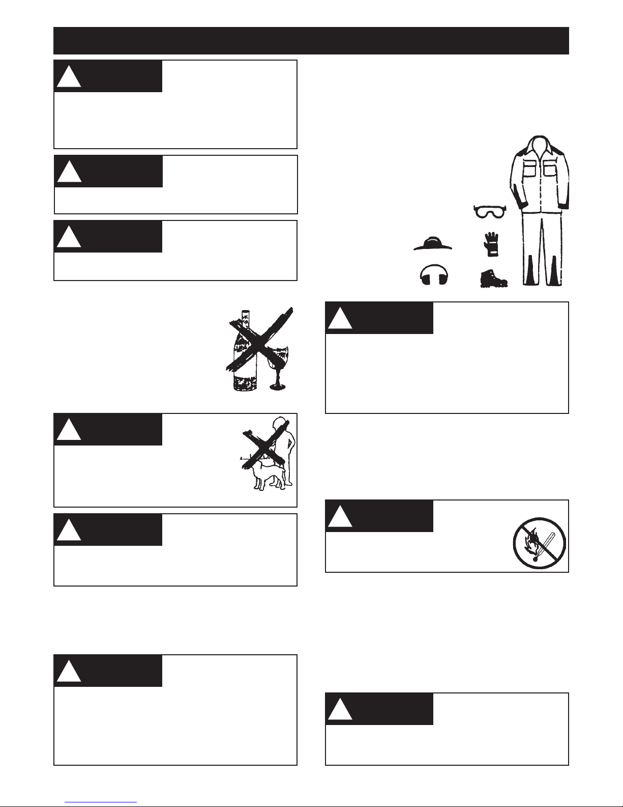
Proper eye protection is a
must. The tine cover may
not protect the operator
from all moving foreign objects, even though the
discharge is directed away from the operator, as
ricochets and bouncebacks may occur during
cultivating operations. Never operate an Atom Tiller
unless wearing goggles or properly fitting safety
glasses with adequate front and side protection
which comply with ANSI Z 87.1.
!
WARNING
Gasoline is an extremely
flammable and
explosive fuel.
Use extreme caution when handling
gasoline. Do not smoke or bring any fire
or flame near the fuel (Fig. 6).
!
WARNING
Always allow engine to cool
before refueling. Accidental
spillage of gasoline over hot
engine could cause fire or explosion to occur with
consequent possible disfigurement or fatal injury.
Wash and clean hands after fueling.
!
WARNING
Replace immediately broken or cracked tine covers.
Engine noise may damage your hearing. Wear sound barriers
(ear plugs or ear mufflers) to protect your hearing. Continual and
regular users should have their hearing checked regularly.
SAFE FUELING INSTRUCTIONS
PROPER CLOTHING
Clothing must be sturdy and snug-fitting, but allow complete
freedom of movement (see Fig. 5). Avoid loose-fitting
jackets, flared or cuffed pants, or anything that could trip
the operator. Wear overalls or long pants to protect your
legs. DO NOT wear shorts. Use of gloves when working
with the Tiller is recommended.
Good footing is most important. Wear
sturdy shoes with nonslip soles. DO
NOT wear sandals or operate with bare
feet. In hot or sunny
conditions, always
wear a hat and
long sleeve shirt for
protection against
skin cancers. Use
of good brand of
sunscreen cream is
also recommended
on exposed skin
surfaces.
Refuel outdoors only. Always switch off the engine
and allow it to cool before refueling. Relieve fuel tank
pressure by loosening fuel cap slowly. Never remove
fuel filler cap while engine is running.
Select bare ground for fueling, then move at least 3 metres
(10 feet) from the fueling spot before starting the engine.
Wipe off any spilled fuel before starting your Atom Tiller and
check for leakeage. Always use a funel to fill the tank.
Always tighten fuel filler cap securely after fueling.
FIG 3
FIG 4
FIG 5
Page 4

The Atom Tiller unit uses an oil-gasoline mixture for fuel
(Refer “Fuel Mix and Fuelling”) for the two stroke engine
and unleaded gasoline only for the four stroke engine.
SAFE STARTING
You should always inspect your unit before starting it. Make
sure the controls and safety devices are working properly.
Place the machine on firm ground or other solid surface in
an open area. Maintain good balance and secure footing.
4
The Atom Tiller is a one person machine. To reduce
the risk of eye or other
injury from thrown objects, ensure that bystanders
are at least 15 metres (50 feet) away during use. If
approached, release throttle trigger to immediately
de-eccelerate the engine. Replace immediately any
worn or broken blade cover.
!
WARNING
!
NOTE
When you pull the starter grip, do
not wrap starter rope around your
hand. Do not allow grip to snap
back, but guide starter rope slowly back to permit
rope to rewind properly.
SAFETY PRECAUTIONS (CONTINUED)
Failure to follow this procedure may result in injury to hand
or fingers or may damage the starter mechanism.
SAFE WORKING INSTRUCTIONS
AND IMPORTANT ADJUSTMENTS
Never operate your machine if it is damaged, improperly
adjusted or not completely and securely assembled. At
correct idle speed, the tines should not turn. Do not use
the Atom Tiller with incorrect idle speed (refer to the speed
setting instructions on page 9).
SAFE MAINTENANCE, REPAIR
AND STORING
Use only original Atom replacement parts for maintenance
and repair. Use of parts manufactured by others will void
warranty and/or may cause serious or fatal injury.
Always stop the engine,
make sure that the tines
have stopped, before
adjusting tine height, before doing any maintenance
or repair work, or cleaning the unit or tines.
!
WARNING
A worn or damaged muffler
is a fire hazard and may
cause loss of hearing. Check
to see that the muffler is in good condition. the tiller
must not be operated if the muffler is not functioning
properly, is damaged, or has been removed. In order
to reduce the risk of fire, do not modify or remove
any part of the muffler and ensure it is not worn or
broken.
!
WARNING
Follow the maintenance instructions in the appropriate
section of this manual. Any repairs should be carried out
by a person with suitable sevicing experience.
Never touch a hot muffler as
burns will result.
!
WARNING
Remember that the risk of forest or grass fires is greater
in hot weather.
Check fuel filler cap for leaks at regular intervals. Use the
specified spark plug and make sure it and the ignition lead
are always in good condition.
Store Atom Tiller in a dry, high or locked location and out
of reach of children.
Never store the machine
with gasoline inside a
building where fumes may
reach an open flame or spark (e.g. gas or oil-fired
heater appliance, electric motor, etc.)
!
WARNING
Before storing for a longer period, always empty the fuel
tank.
Keep the space behind and beside the engine clear at
all times to allow for the escape of hot and toxic exhaust
fumes.
Operate your machine under good visibility and daylight
conditions only. Work carefully.
Start and operate your unit
outdoors and in a ventilated
area.
!
WARNING
SAFE WORKING CONDITIONS
When working with the Atom Tiller, always wrap your fingers
tightly around each handle grip. Keep your hands in this
position to have your machine under control at all times.
NEVER attempt to operate the Atom Tiller with one hand,
as a loss of control may result in serious or fatal injury.
Make sure the handle grips are in good condition and free
of moisture, oil or grease. Use both hands, one on each
handle, to operate and control the tiller. Do not overreach.
Keep proper footing and balance at all times.
The engine exhaust from
this product contains
chemicals known to the
State of California to cause cancer, birth defects or
other reproductive harm.
!
WARNING
Do not touch hot engine
during and immediately
after use as you may burn
yourself.
!
WARNING
Do not lift tiller with engine
running, always switch off.
!
WARNING
Page 5

FIG 9B
FIG 9A
FIGURE 7A
Insert 175mm(61/2”) bolt #2 thru the
head retainer #3 (note arrow points
forward) then thru handle tube #1
then thru AV Rubber #12 then thru
Tiller body #4, thru AV Rubber #12
and handle #1.
Screw large wing nut #6 on
protruding bolt and tighten.
Fit cross brace #7 to handles #1 &
#5 with base down as illustrated.
Use 2 screws #8 and lock nuts #9
provided in packet. Use straight
bladed screwdriver (or torx 25
screwdriver) screw on firmly.
NOTE: Throttle cable and switch
wire from engine must be fitted
under engine and Tiller body and
along side cross brace. Clip into
place, back to throttle trigger.
FUEL MIX – 2 STROKE ENGINES
USE AN OIL AND GASOLINE MIXTURE
IMPORTANT
Two-cycle fuel separates and ages. Do not mix more
than you will use in a month. Using old fuel can cause
difficult starting or engine damage. Shake fuel container to
thoroughly mix fuel before each use. Do not attempt to run
your engine on gasoline only; this will cause engine failure
and void engine warranty.
Do not use outboard engine motor oil. Only use specialised
2-stroke oils from lawn and garden equipment shops.
Remember …
• Always mix two-cycle oil with gasoline before fueling
your tiller. Never, ever run your tiller on gasoline alone.
This will ruin your engine and void all warranties.
• Always use a clean gas can and always use unleaded
gas.
• Never try to mix the oil and gasoline in the engine fuel
tank.
• Always mix oil and gas in the proper proportions: 125ml
of two-cycle engine oil to 4 litres of unleaded gasoline
Fig. 9A.
PLEASE READ SAFE FUELLING INSTRUCTIONS – Page 3
5
ASSEMBLING THE lllATOM TILLER
FUEL & OIL – 4 STROKE ENGINES
DO NOT USE OIL AND GASOLINE MIX ON
4 STROKE ENGINES
1. Use clean, fresh unleaded gasoline.
2. Use clean engine manufacturers recommended oil (see
seperate booklet supplied with 4 stroke engine supplied) or
SAE 10-30W synthetic oil. Fill crankcase to correct level.
WARNING using non synthetic oil or 2 stroke oil will shorten
engine life.
3. ALWAYS check your oil every second or third fill. Regular
check of oil levels is essential. Change oil after first hour
then every 6 hours. Lack of oil and infrequent change of
oil will destroy engine.
4. With some tillers, lay tiller on side to fill with gasoline
Fig. 9B.
FIG 7B
Insert Trigger Handle #10 onto right handle tube #5 using one screw #8 one nut #9
Fig. 7B. Clip cable into place.
Insert left handle #11 into left handle tube using screw #8 and nut #9 screw on firmly.
Clip on cable clamp with throttle cable and switch wire as shown #13 Fig. 7A.
Attach wheel arm axle #14 through large hole in Tiller body. Use bolt #15 and washer #16
and screw into wheel arm axle and tighten.
FIG 8
UPPER OIL LEVEL
OIL FILLER NECK
ENGINE OIL FILLER CAP
HONDA ENGINE SHOWN
FURROW PLOW
ATTACHMENT
Refer p.15.
FIG 7A
Page 6
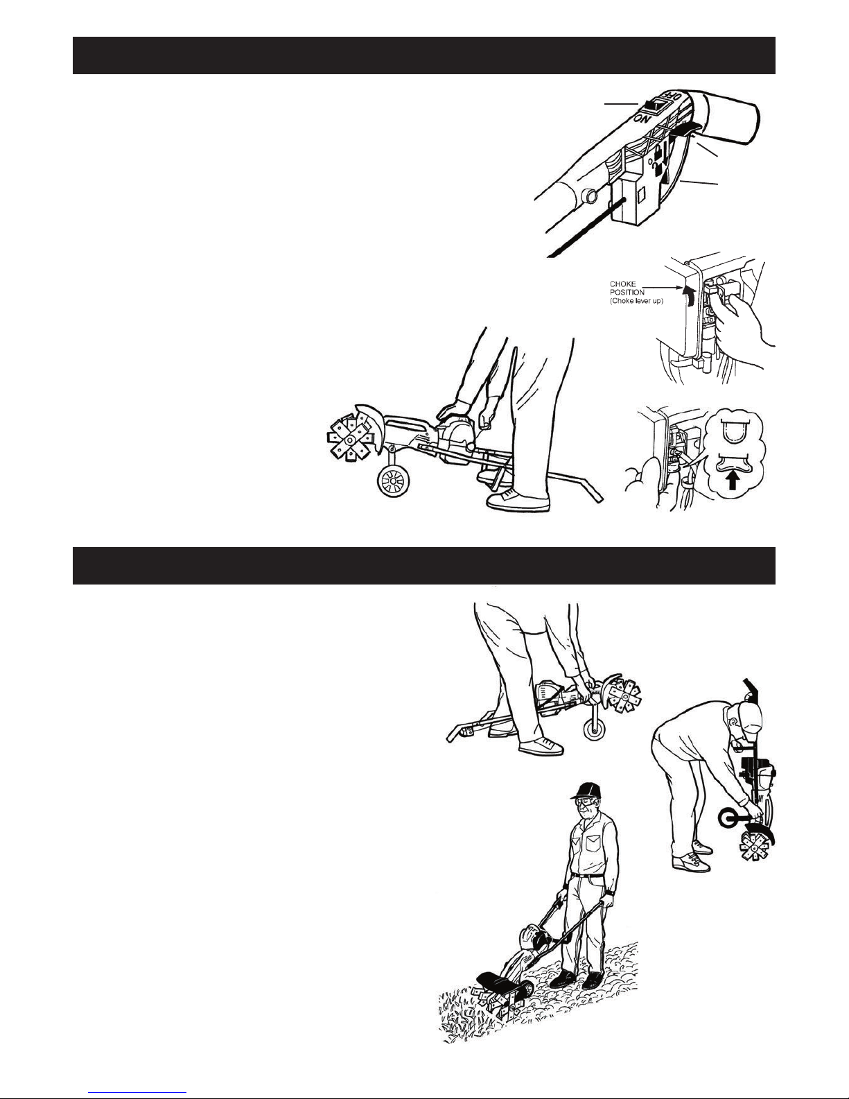
FIG 15B
FIG 15A
FIG 14
FIG 11
SAFETY
INTERLOCK
THROTTLE
TRIGGER
SWITCH
FIG 13
Place Tiller on ground in horizontal position See Fig. 14 below.
COLD START
1. Switch engine on (Fig 11).
2. Slide choke lever up to full choke position (Fig. 12).
3. Press and release the primer bulb
5-8 times (Fig. 13).
4. Make sure you have a firm footing. Hold down motor with left hand. Put
one foot lightly on cross brace. With right hand pull the starter grip slowly
until you feel it engage – and then give it a pull (Fig. 14).
5. When engine starts to run allow it to run on half choke for a few seconds to
warm up, then push choke down to engine run position.
6. Throttle Trigger (engine accelerator control is operated by pushing down
interlock with thumb and pulling on trigger (Fig. 11).
STARTING & STOPPING INSTRUCTIONS
6
COMBINATION CULTIVATING, TILLING, ROTARY HOEING
1. The Atom Tiller is very easy and simple to use. It only
takes a few minutes to become an efficient user.
2. Thoroughly inspect the area where the tiller is to be
used and remove all long grass, stones, sticks, wires
and other foreign objects.
3. Adjust tine depth (Fig. 15(a)(b). Try the third hole closest
to operator.
4. Start motor.
5. With both arms fully extended downwards, (Fig. 15C),
hold both handle grips firmly. With the engine running,
pull the throttle trigger full on after depressing safety
interlock. Engine must run at three quarter to full speed
for best tilling results.
6. As tilling action begins, the tines dig and move the tiller
forward.
7. NOTE: to reduce “Forward Pull” of tiller, adjust wheel
arm for shallow depth.
8. Continue at a moderate pace until you are familiar with
the controls and handling of the Atom Tiller.
NOTE: after allowing the tiller to cultivate 500mm you
can pull it back towards you and then allow the unit to
move forward again. You can repeat this procedure
over the area you are cultivating. Always have a firm
footing.
9. Mulching. The tiller is ideal to mix, cut lawn clippings,
leaves etc into your garden bed. This method accelerates
mulching/composting process.
10. To go deeper adjust wheel arm adjustment forward or lift
handles. To go shallower adjust wheel arm adjustment
rearwards or push handles down.
HOT OR WARM START
7. Switch ignition on and follow instruction
3 & 4.
FLOODED ENGINE
8. Ignition ON, choke lever in run
position.
9. Pull starter rope up to 10 times to clear
excess fuel.
10. If engine has excessive fuel that cannot
be cleared, remove spark plug from
engine and from spark plug terminal,
crank engine to clear excess fuel, wipe
and dry spark plug of all fuel, re-install
spark plug terminal, and restart as
above. Otherwise allow to stand for 30
minutes before restarting.
FIG 12
FIG 15C
Page 7

If tines jam or stop (tines no longer rotates) switch motor
off and remove spark plug lead. Place machine upright
with handles on ground (Fig.16). Remove obstruction.
7
Operate unit carefully. Be
very careful walking
backwards as you may trip,
fall and injure yourself. Always have a firm footing.
!
WARNING
!
NOTE
When cultivating efficiently,
engine speed should be three
quarters to full throttle under load.
Operating at low engine speed will shorten clutch life.
COMBINATION CULTIVATING, TILING, ROTARY HOEING (CONTINUED)
The tines will rotate when
engine is idling fast, e.g. on
starting or when engine is
cold. TO STOP ENGINE press “STOP” down on switch.
!
WARNING
Failure to switch off motor
to clean tines could lead to
very serious injury of hands.
Always wear gloves to clean.
!
WARNING
Clutch: The Atom Tiller
is equipped with a
centrifugal clutch.
DO NOT run tiller
at low speeds (or, if
jammed, at high engine
speeds) as clutch
shoes will prematurely
wear and cause
damage, Fig 17.
!
NOTE
Keep inside of tiller guard clean,
especially in wet conditions. A
clogged guard can slow down
or stop tine rotation and may cause damage to
automatic safety clutch.
Clean tines of grass, rocks and sticks, always using gloves
as the tines are self sharpening and are very sharp. You
could cut yourself. Remove tine cover as follows. Lift knob
Fig. 18A and slide cover forward Fig 18B. If jammed cover
can be tapped off with a soft hammer.
Leveling uneven ground: The tiller if used carefully can level
uneven ground for a good garden bed. Use your arms to work
the tiller forwards and backwards on high points.
After leveling pre-work all surfaces to prepare the new flat bed.
Use a rake to smooth out and tidy up.
The cultivator can be transported by pushing it on it’s wheel.
Very hard ground, clay or rocky conditions: The Atom
rotary tiller is NOT DESIGNED for very hard ground, hard
or rocky conditions. These kinds of soil will not make a good
garden bed.
TO AVOID PERSONAL
INJURY, NEVER CARRY
THE TILLER WHILE THE
ENGINE IS RUNNING.
Stop the engine prior to lifting or carrying Fig.20.
!
WARNING
AFTER FINISHING WORK
Storing for a short period: Keep the unit in a dry place
until you need it again. Do not store where open flame or
electrical machinery is operating.
Storing for a long period: Drain the fuel tank and run
engine until carburettor is dry.
TO AVOID PERSONAL
INJURY, NEVER CARRY
THE TILLER WHILE THE
ENGINE IS RUNNING.
Stay clear of the rotating tines. Stop the engine prior
to making adjustments and cleaning.
!
WARNING
FIG 19
FIG 20
FIG 16
FIG 18B
FIG 18A
FIG 17
The Tiller can be easily moved as shown above.
Page 8

8
TROUBLESHOOTING
PROBLEM CAUSE REMEDY
MAINTENANCE INSTRUCTIONS
Engine will not run or
runs and stops.
1. Ignition switch is OFF.
2. Choke ON.
3. Partially empty fuel tank.
4. Primer bulb not pushed enough times.
5. Engine is flooded.
6. Dirty or blocked fuel or air filter.
1. Ignition switch to be in run position.
2. Push choke off (down).
3. Fill tank.
4. Press primer bulb fully and slowly 5/10
times.
5. Use correct start procedure.
6. Clean or replace fuel or air filter.
Cutting tines do not
turn when operating.
1. Tine and cover filled with dirt/
grass, sticks, rocks.
2. Clutch slipping.
3. Loose tine nut.
4. Choke partly on.
1. Clean.
2. Less depth. Check tines are rotating.
3. Tighten tine nuts both sides.
4. Slide choke off.
Gear case leaking 1. Loose screws.
2. Broken O-ring.
3. Grease too thin or oil used.
1. Tighten.
2. Replace O ring
3. Refill with correct grade grease.
Noisy gears 1. No lubricant in gearcase.
2. Loose tine nuts.
1. Refill.
2. Reassemble parts correctly.
!
NOTE
Tines are self tightening,
excessive tension is not required.
LOOSE TINES
Check that all tines are in correct position and are tight
together, no gaps or foreign material between them. Tighten
nut clockwise on LH side of unit Fig 21B and anti clockwise
on RH side Fig 21A as shown on top of tine cover.
USE ONLY ATOM PATENTED
TILLER TINES. Other tines
are not designed for this
unit. Other tines can also break and cause injury.
!
WARNING
TO REMOVE TINES
Undo nuts at end of blade shaft as shown. Remove all
components. Check shaft for any dents etc. and smooth
off with an abrasive paper.
!
NOTE
Do not run engine without tines
tightened to tine shaft as gear
damage will occur.
RIGHT HAND SIDE
(Standing behind tine cover)
FIG 21A
LEFT HAND SIDE
(Standing behind tine cover)
FIG 21B
FIG 22
FIG 23
WARNING: When using
air tools remove nut but
do not overtighten when
refitting.
NOTE: Tine assembly
sequence.
Page 9
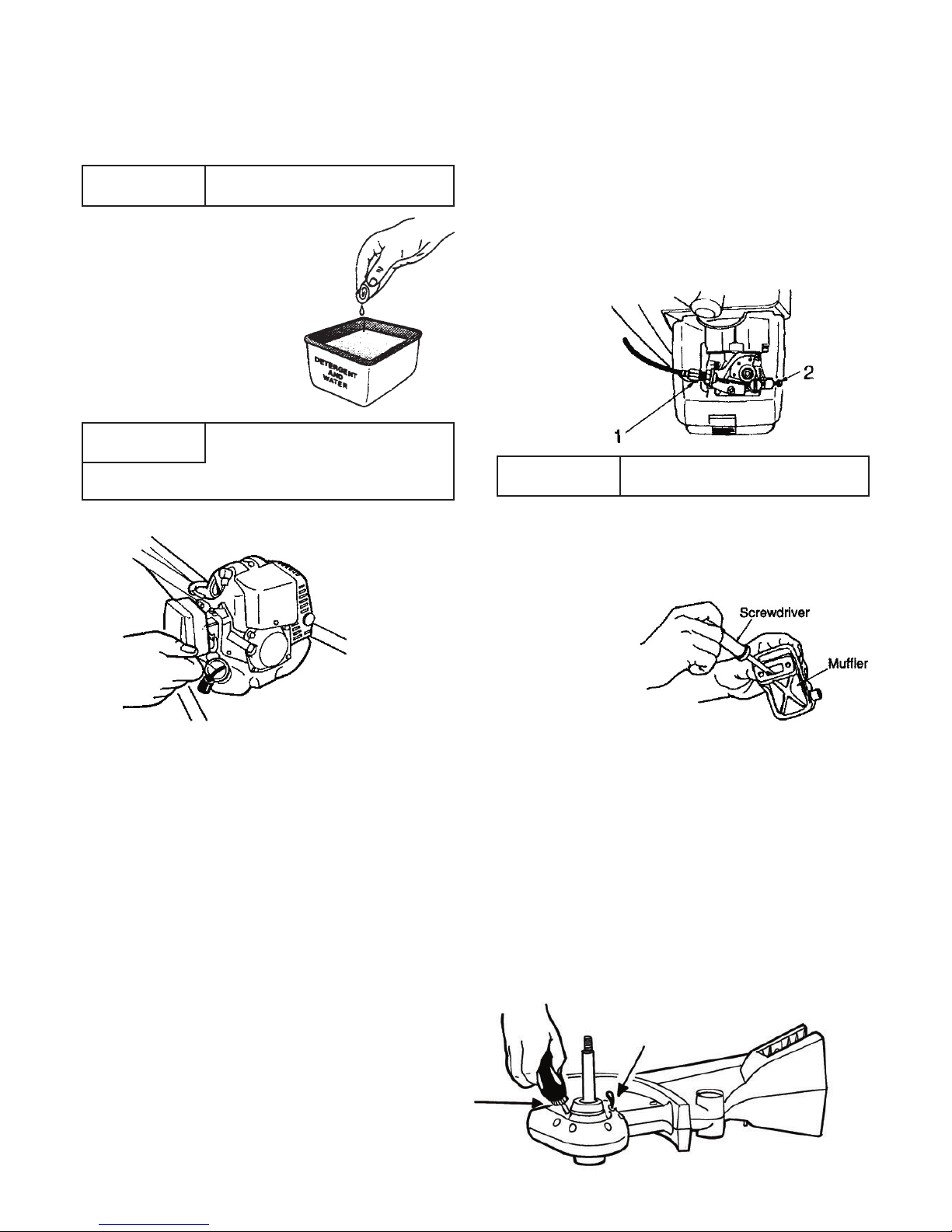
FIG 25A
Top view
looking down
on carburettor.
9
!
NOTE
CLEAN AND RE-OIL THE AIR
FILTER EVERY 5 HOURS OF USE.
AIR FILTER MAINTENANCE
The air filter is one of the most important areas to maintain.
If it is not maintained, you will void the warranty. Before
cleaning, make sure the unit is turned off.
1. If filter torn or very dirty
replace.
2. Wash the filter in detergent
and water (Fig 24A). Rinse
the filter thoroughly and
allow it to dry.
3. Apply enough clean engine
oil to saturate the filter when
squeezed. Squeeze the
filter to spread the oil and to
remove excess oil.
!
NOTE
If the unit is operated with dry or
dirty filter or without the air filter
and/or carburettor air filter cover,
you will void the warranty.
FUEL FILTER MAINTENANCE
A dirty or blocked fuel filter will stop fuel flow. To clear, use
a piece of hooked wire to “fish” filter out of tank. Clear with
compressed air or replace filter.
CARBURETTOR
This unit is equipped with a diaphragm-type carburettor
that has been carefully calibrated at the factory. In most
cases, no further adjustment will be required. The condition
of the air and fuel filter is important to the operation of the
tiller. A dirty air filter will restrict the air flow, which upsets
the fuel-air filter mixture in the carburettor and a dirty fuel
filter will restrict flow of fuel resulting in symptoms indicating
that carburettor may need cleaning. Therefore, check the
condition of the air filter and fuel filter before adjusting the
carburettor.
• The engine will not idle.
• The engine hesitates or stalls on acceleration.
• The loss of engine power that is not corrected by
cleaning the air filter, fuel filter and muffler then the
carburettor should be dismantled and cleaned. Refer
to parts breakdown page 14.
!
NOTE
Tiller tines NOT to rotate when
engine is idling.
FIG 24A
ADJUSTING IDLE SPEED
1. The idling screw adjustment is accessible without
removing the air filter cover. See Fig 25A. To increase
engine idle speed, turn IDLE SCREW (2) clockwise.
To decrease engine speed, turn IDLE SCREW counter
clockwise (anti-clockwise). Throttle trigger to be in idle
position.
NOTE: If the motor has been removed. On refitting it is
to be pushed fully into the tiller casing and three screws
“A” Fig 28(p.10) are screwed up tight. Misalignment due
to incorrect fitting can cause clutch to engage at idle. To
correct, loosen screws re-straighten motor and re-screw up
equally three screws.
CLEANING THE MUFFLER
After a long period of use the exhaust can block and must
be cleaned. Remove engine cover and muffler and clean
out all passages, Fig 25B. Blow loose material out of muffler.
Ensure no grit enters cylinder exhaust opening.
LUBRICATION OF GEARS
There is usually sufficient lubricant to last at least 4 years or
100 hours of use before topping it up. The lubricant in the
gear case should be added according to use. Remove tines
on left side (only) and clean casing around fill and bleed
screws. Remove two screws marked FILL and BLEED.
Inject grease into FILL screw hole and allow lubricant to
eject from BLEED hole indicating gear box is full (Fig 26).
Refit and tighten BLEED screw and squeeze in 3 or 4 more
lots of lubricant. Refit FILL screw and tighten.
NOTE: Special blended lubricants are used in the gear box.
Only use Penrite brand semi fluid tiller grease, available in
squeeze bottles P/N # 63220. Other grease or oils could
lead to early gear failure or overheating of gears and casing.
If gear case shows leakage, tighten all screws or dismantle
and replace ‘O’ ring see page 11. A gasket sealant can also
be used to assist sealing.
FIG 24B
FIG 25B
FIG 26
MAINTENANCE INSTRUCTIONS (CONTINUED)
Cable
Adjustment
Idle
Screw
Page 10

FIG 28
A
A
A
FIG 31
CHECKING THE SPARK PLUG
If engine is low on power, difficult to start or runs poorly at
idling speed, check the spark plug.
• Allow engine to cool down. Remove spark plug.
• Clean dirty spark plug or replace with new spark plug.
• Check electrode gap (see Fig 27).
• Rectify faults which have caused fouling of spark
plug. Possible faults include:
– Too much oil or wrong type of oil in fuel tank in
two stroke engine.
– Dirty air filter or fuel filter.
– Unfavourable running conditions (e.g. operating
at part load).
– Wrong oil infrequent changes or oil usage in four
stroke engine.
Do not clean the spark plug in an abrasive grit spark plug
cleaner, as expensive damage to the engine could occur
through loose grit damaging chrome in cylinder bore.
Fit a new spark plug after approximately 50 operating hours
or earlier if electrodes are badly eroded.
Recommended spark plug is a NGK 8PMR7A, or equivalent.
Specified electrode gap is: .20”, 15mm.
10
!
NOTE
Using spark plugs other than
those designated may result in the
engine failing to operate properly or
in the engine becoming overheated and damaged.
TO REMOVE ENGINE
1. Preferably use a No.25 torx Screwdriver, loosen and
remove 3 screws (A) located as shown fig. 28.
2. Pull engine away from body (Fig 28). It is NOT
necessary to remove handles.
FIG 27
FIG 33
FIG 32B
FIG 32A
FIG 29
TO REPAIR THROTTLE TRIGGER
ASSEMBLY
1. Remove 2 screws and remove cover and all parts. Re-assemble
as follows.
2. Fit throttle inter-lock compression spring (Fig 30).
3. Fit trigger then compression spring, then switch and throttle
cable (Fig 31/32). Note forward position of throttle spring fits over
retainer post.
4. Hold trigger in place with finger until throttle cover is fitted (Fig 33). It
is then ready for screwing tight (with 2 screws. Ensure throttle cover
rear tabs (arrowed Fig 33) engages underside of handle wall.
NOTE: CORRECT POSTION
OF THROTTLE CABLE.
WORKSHOP MANUAL
TO REMOVE AND REPLACE
CLUTCH DRUM
Remove motor, hold unit and spin off clutch nut anti
clockwise with impact driver. Replace parts as required.
Reverse procedure to re-install.
TO REMOVE WHEEL ARM
Undo 1/4 hex bolt and pull wheel arm thru casing.
FIG 30
!
NOTE
This information is for persons with suitable servicing experience should this unit ever require
workshop repair.
Page 11

11
FIG 34
WORKSHOP MANUAL (CONTINUED)
DISMANTLING & RE-ASSEMBLING
MAIN BODY
RECOMMENDATIONS
Factory built service assemblies (see Page 13) are a quality
and cost effective method of repair.
1. Remove engine (Fig 28).
2. Remove tine cover (Fig 18A/B).
3. Undo handle nut and remove handles Fig. 7.
4. Remove wheel arm bolt and wheel arm Fig. 29.
5. Remove tines both sides Fig. 21/22, clean shaft and
remove all scratches, smooth with emery paper.
6. Remove all screws seen on LH case.
7. Carefully separate both casings. Tap end of shaft
with copper or soft hammer to split casing. Slide
casing off.
8. Thoroughly clean and inspect gears and drive pin
bearings, seals. Replace any worn parts.
9. Renew sealing ring seal if necessary.
Fit sealing ring around bearing as illustrated.
10. Slide tine shaft with gear partly thru bearing of right
hand casing.
NOTE: Pour Penrite semi fluid grease P/N 63220
and fill up casing 3/4 full.
11. Carefuly fit sealing ring in place. Pre rolling the
sealing ring will allow it to wrap around the sealing
lip at the casing.
A silicone gasket sealant will assist in sealing any
worn casings and around the thrust block.
12. Slide casing over shaft and press down onto lower
case.
13. Start screwing from position centre of gear case then
evenly on each side. Turn clutch drum frequently to
ensure gears turn.
14. To complete assembly of unit reverse above
procedure (1) to (5). Replace tines if required.
Page 12

12
lllATOM ROTARY TILLER
Page 13

13
lllATOM Industries
Parts List Gasoline Tillers Models Tiller Komatsu 26cc & Tiller Honda 25cc
KEY # PART # DESCRIPTION
1 40650 SCREW M5 x 36MM
2 40651 SCREW M6 x 16MM
3 40652 NYLOC NUT 5MM
4 42111 27.2 X 12.6 WHEEL SEAL
5 43169 FLANGE NUT 3/8 UNC
6 43172 NUT NYLOC 3/8 UNC
7 43173 M12 X 1.75RH NUT
8 43184 SPRING PIN 3/16 X 1.1/4
9 43198 TRIGGER COMP. SPRING
10 43199 SPRING, SMALL
11 43218 3/8 FLAT WASHER
12 43452 HT. ADJ ARM COMP SPRING
13 43485 CLUTCH WASHER 12.06 X 22 X 12
14 43765 WHEEL ONLY
15 43790 5.5MM SCREW FOR PLASTIC
16 43868 BEARING 6003-2HR 4MM SHOULDER
17 43935 CABLE ADJUSTER PIN *
18 43955 CASING AV RUBBER
19 43966 HONDA AIR DEFLECTOR(GX25)
20 44005 BRASS TERMINAL 6.3MM
21 44006 NUT 1/4 BSW
22 44060 UNIVERSAL HANDLE TUBE
23 44064B HANDLE BOLT HEX PIECE
24 44075B HANDLE KNOB
25 44168 SWITCH WIRE & SWITCH 1035MM
26 44302 HEIGHT ADJ ARM PIN
27 44305 WHEEL BRG 28X8X12.8MM
28 44318 CLUTCH DRUM CUP 54MM
29 44427 THROTTLE CABLE 945MM
30 44690 NUT M6 *
31 45112 NUT M12 X 1.75 LH
32 47009 ENGINE MOUNT GX25 KZ26
33 48004 HONDA GX-25 ENGINE
34 48016 EXHAUST GAS DEFLECTOR
35 50098 BEARING 32 X 10 X 12
36 62777 CROWN GEAR TILLER
37 62778 WORM GEAR TILLER
KEY # PART # DESCRIPTION
38 62795 WASHER 6.6 X 28.4 X 1/4
39 62833 GEAR SEAL TILLER
40 62843 HEX BOLT 3.5 X 1/4 BSW
41 62844 HEX BOLT 3 X 3/8 BSW
42 62845G RH CASING TILLER
43 62845R RH CASING TILLER
44 62846G LH CASING TILLER
45 62846R LH CASING TILLER
46 62847B BLADE COVER 250MM
47 62848B BLADE COVER 350MM
48 62849B WHEEL ARM TILLER
49 62850B HEIGHT ADJ HANDLE TILLER
50 62851B TINE SPACER LARGE 45MM
51 62852B TINE SPACER SMALL
52 62891 TINE SHAFT 250MM
53 62892 TINE SHAFT 350MM
54 62903 WHEEL SPACER SMALL 41.5MM
55 62912 FLANGE DRUM HUB
56 62919 NUT NYLOC 1/4 UNC
57 62921 TINE DRUM 17MM
58 62922 WASHER TINE 17MM
59 62925 DRIVE SHAFT UNIVERSAL
60 62948 TILLER TINE
61 62964 NEEDLE BEARING 12 X 26 X 2MM
62 62965 THRUST WASHER 12 X 26 X 1.5MM
63 62969G KZ 26 EXHAUST PLUG *
64 62972 BEARING SEAL
65 62982 BEARING WASHER 32 X 18 X 1.6MM
66 62983 HARDENED WASHER
67 62986B TILLER COVER KNOB
68 62993 KOMATSU ENGINE KZ26 *
69 62999 TILLER TINE SHAFT SEAL
70 63017B RH HANDLE WITH RUBBER
71 63019B LH HANDLE WITH RUBBER
72 63020B CROSS BRACE
73 63021B RH HANDLE COVER SWITCH
74 63022R THROTTLE TRIGGER
KEY # PART # DESCRIPTION
74 63022R THROTTLE TRIGGER
75 63023R THROTTLE INTERLOCK
76 63049 HEX BOLT 6.5 X 1/4 BSW
77 63052 BEARING BLOCK
78 63064 MANUAL ALL GAS TILLERS
79 63065 WARNING LABEL TILLER GUARD
80 63220 TILLER SEMI-FLUID GREASE
81 63217 WIRE & CABLE CLIP
SERVICE ASSEMBLIES
82 63192 WHEEL ARM & WHEEL ASSM
83 63194 WHEEL ASSEMBLY
(84) 63195G MAIN CASING ASSM 250MM GREEN
(85) 63195R MAIN CASING ASSM 250MM RED
(86) 63197G MAIN CASING ASSM 350MM GREEN
(87) 63197R MAIN CASING ASSM 350MM RED
(88) 63209 12 TILLER TINES PACK
(89) 63208 8 TILLER TINES PACK
90 63211B BLADE COVER ASSM 250MM
91 63212B BLADE COVER ASSM 350MM
92 63213 RH HANDLE ASSM
MAIN CASING ASSM INCLUDES
5, 15, 16, 28, 35, 36, 37, 39, 42, 44, 55,
59, 61, 62, 64, 65, 69, 77, 80
OPTIONAL EQUIPMENT (not shown)
63183 FARROW ATTACHMENT
63204 8 TINE COMBINATION AERATION
& DE THATCHING BLADES
63205 12 TINE COMBINATION AERATION
& DE THATCHING BLADES
* NOT ILLUSTRATED
SERVICE ASSEMBLIES
We recommend using factory produced service assemblies for replacements as they are more economical
and reduce labour costs and time to repair.
COLOURS: B = Black
G = Green
R = Red
Page 14

14
lllATOM 26cc KZ Engine Parts List
1 63085 T1800-12110 Cylinder
2 63086 5500-12213 Gasket, Base
3 63087 1850-12130 Bolt, M5XL22
4 63088 550-21100 Crankcase Comp.
5 46604 2629-21130 Pin
6 63089 5500-21141 Gasket, Base
7 63090 06030-06001 Bearing
8 46124 2169-21210 Seal
9 63091 1850-21220 Seal
10 63092 04065-02812 Snap Ring
11 46130 01252-30530 Bolt, M5XL30
12 63093 5500-42001 Crankshaft Comp.
13 63094 5500-22110 Guard
14 63095 0263-90514 Screw, M5XL14
15 63096 5910-41110 Piston
16 63097 5910-41210 Ring, Piston
17 63098 1600-41310 Pin, Piston
18 63099 1260-41320 Snap Ring
19 63100 5500-41410 Bearing
20 63101 1101-41340 Washer
21 63103 T1610-15110 Muffler
22 63102 01252-30550 Bolt
23 63104 T1600-15210 Gasket, Muffler
24 63105 5500-15221 Plate, Muffler
25 63106 0263-90413 Screw
26 63107 T1700-13160 Insulator
27 63108 5500-13121 Gasket, Insulator
28 46114 0263-90520 Screw
29 46647 5933-73110 Spark Plug 8PMR7A (NGK)
30 63109 T1700-71201 Coil, Assy
31 63110 5500-72110 Cap, Plug
32 63111 T1700-71220 Cord
33 46174 2616-71320 Cap, Coil
34 46176 5500-72130 Grommet
35 63112 5500-72120 Spring, Plug
36 63168 3310-72150 Bolt
37 63113 T1700-71260 Spacer
38 63114 T1700-73200 Cord Comp
39 63115 T1700-71110 Rotor
40 46154 1650-43230 Nut, M8
41 46156 1000-43240 Key
42 63116 848EA051DO Shoe, Clutch
43 63117 T1700-51220 Spring
44 63118 1140-51250 Screw, Clutch
45 63119 1140-51230 Washer
46 63120 1970-51241 Washer Wave
47 63121 848EAX7510 Recoil, Assy
48 63122 848EAX7550 Case Comp
49 63123 848E4075CO Reel
50 63124 848E4075DO Plate, Cam
51 63125 848E4075GO Spring, Damper
52 46655 1850-75130 Spring, Spiral
53 63126 848E4075EO Screw
54 63127 848E4075FO Rope
55 46228 1140-75320 Knob
56 46660 5500-75170 Plate, Stopper
57 63128 T1700-32162 Screw, M4XL16
58 63129 848EAX7520 Pulley Assy
59 63130 848EAX75PO Pulley, Starter
60 63131 848E4075RO Ratchet
Atom KZ
Key # Part # Part # Description
Atom KZ
Key # Part # Part # Description
61 63132 848E4075SO Spring, Return
62 63133 848E4075TO E-Ring
63 63143 T1807-75R10 Label, Recoil
64 63135 T1807-3110 Label
65 63136 T1815-31110 Co ver, Fan
66 46114 0263-90520 Screw
67 63137 T1600-72210 Clamp
68 63138 0263-90510 Screw
69 63139 848EGE31AO Cover, Engine
57&70 43128 T1700-32162 Screw, M4XL16
71 63140 5500-13131 Gasket, Carburetor
72 63141 848EGA8100 Carburetor Assy
73 63142 1794-81450 Body Assy
74 46670 3306-81380 Screen
75 46671 3356-81310 Valve, Inlet
76 63143 1794-81270 Spring, Lever
77 46673 1850-81220 Screw
78 46674 3310-81250 Pin
79 46675 3310-81230 Lever
80 46676 1850-81490 Body
81 46677 1850-81520 Cover, Pump
82 46678 1751-81510 Pump, Priming
83 46679 3310-81260 Diaphragm, Meterin
84 46680 1850-81470 Gasket
85 46681 1065-81420 Diaphragm, Pump
86 46682 1065-81410 Gasket
87 63144 T1800-81250 Jet
88 46684 1751-81240 O-Ring
89 46685 1751-81130 Ring
90 46686 1881-81140 Swivel
91 46694 5500-81160 Washer
92 63145 T1700-81150 Vale Assy
93 46688 1752-81110 Screw
94 63146 5500-81120 Bracket
95 46690 1751-81180 Nut, Adjust
96 63147 2730-81170 Screw, Adjust
97 46692 1881-81130 Ring
98 46693 1850-81530 Screw
99 63148 T1700-82100 Body, Assy
100 63149 1970-82190 Sleeve
101 63150 T1700-82130 Plate, Choke
102 63151 T1700-82140 Lever, Choke
103 63152 2630-33610 Screw
104 63153 5500-82171 Element
105 63154 T1701-82200 Cover Assy
106 63155 5500-82221 Knob
107 63156 0263-90560 Screw
108 63157 T1800-85001 Tank Assy
109 63158 5607-85201 Cap Assy
110 63159 5601-85300 Holder Assy
111 63160 5500-85220 Packing
112 63161 5601-85260 Filter
113 63162 4820-85260 Stopper
114 46712 5500-85300 Pipe Comp
115 63163 5500-85400 Filter Assy
116 63164 1260-85460 Clip
117 63165 5500-85510 Screw
118 63166 5910-85510 Screw
119 63167 1950-86120 Clip
Page 15

NOTES
15
FITTING FURROW PLOUGH
ATTACHMENT
After tilling/cultivating is completed, fit furrow plow.
Line up hole in plough #17 with hole in wheel arm #14 and
place bolt #15 through plough and wheel arm. Tighten with
wing nut #6.
Set depth of wheel arm at about No.3 or 4 setting. This
height may vary according to condition.
Page 16

Atom warrants each new Atom Product Model for ONE YEAR
for home owner use and 90 days for commercial use based
on the following terms.
The warranty extends to the original retail purchaser only and
commences on the date of the original retail purchase.
Any part of the Atom Product manufactured or supplied by
Atom and found in the reasonable judgement of Atom to
be defective in material or workmanship will be repaired or
replaced by an authorized Atom service dealer without charge
for parts and labour.
The Atom Product, including any defective part, must be
returned to an authorized service dealer within the warranty
period. The expense of delivering the Atom Product to the
dealer for warranty work and the expense of returning it
back to the owner after repair or replacement will be paid
for by the owner. Atom’s responsibility in respect to claims is
limited to making the required repairs or replacements and no
claim of breach of warranty shall be cause for cancellation or
rescission of the Contract of Sale of any Atom Product. Proof
of purchase will be required by the dealer to substantiate any
warranty claim. All warranty work can be performed only after
authorisation has been given to the service dealer.
This warranty is limited to NINETY (90) days from the date
of original retail purchase for any Atom Product that is used
for commercial purposes and ONE (1) month for rental
purposes.
This warranty does not cover any Atom Product that has
been subject to misuse, neglect, negligence or accident, or
that has been operated in any way contrary to the operating
instructions as specified in the Atom Operator’s Manual. This
warranty does not apply to any damage to the Atom Product
that is the result of improper maintenance or to any Atom
Product that has been altered or modified so as to adversely
affect the product’s operation, performance or durability or that
has been altered or modified so as to change its intended use.
The warranty does not extend to repairs made necessary by
normal wear or by the use of parts or accessories which are
either incompatible with the Atom Product or adversely affect
its operation, performance or durability.
Only genuine Atom parts are to be used. Use of non-genuine Atom
parts voids all warranties due to that part not being approved by
Atom to Atom’s specifications.
Atom reserves the right to change or improve the design of any
Atom Product without assuming any obligation to modify any
product previously manufactured.
ALL IMPLIED WARRANTIES ARE LIMITED IN DURATION
TO THE ONE YEAR WARRANTY PERIOD FOR HOME
OWNER OR NINETY (90) DAYS FOR ANY COMMERCIAL
PURPOSE AND ONE (1) MONTH FOR RENTAL PURPOSES.
ACCORDINGLY, ANY SUCH IMPLIED WARRANTIES,
INCLUDING MERCHANTABILITY, FITNESS FOR A PARTICULAR
PURPOSE, OR OTHERWISE, ARE DISCLAIMED IN THEIR
ENTIRETY AFTER THE EXPIRATION OF THE APPROPRIATE
WARRANTY PERIOD. ATOM’S OBLIGATION UNDER THIS
WARRANTY IS STRICTLY AND EXCLUSIVELY LIMITED TO
THE REPAIR OR REPLACEMENT OF DEFECTIVE PARTS
AND ATOM DOES NOT ASSUME OR AUTHORIZE ANYONE
TO ASSUME FOR THEM ANY OTHER OBLIGATION. SOME
STATES DO NOT ALLOW LIMITATIONS ON HOW LONG AN
IMPLIED WARRANTY LASTS, SO THE ABOVE LIMITATION
MAY NOT APPLY TO YOU.
ATOM ASSUMES NO RESPONSIBILITY FOR INCIDENTAL,
CONSEQUENTIAL OR OTHER DAMAGES INCLUDING,
BUT NOT LIMITED TO, EXPENSE OF RETURNING THE
ATOM PRODUCT TO AN AUTHORIZED SERVICE DEALER
AND EXPENSE OF DELIVERING IT BACK TO THE OWNER,
MECHANIC’S TRAVEL TIME, TELEPHONE OR TELEGRAM
CHARGES, RENTAL OF A LIKE PRODUCT, DURING THE
TIME WARRANTY SERVICE IS BEING PERFORMED, TRAVEL,
LOSS OR DAMAGE TO PERSONAL PROPERTY, LOSS OF
REVENUE, LOSS OF USE OF THE PRODUCT, LOSS OR
TIME, OR INCONVENIENCE. SOME STATES DO NOT ALLOW
THE EXCLUSION OR LIMITATION OF INCIDENTAL OR
CONSEQUENTIAL DAMAGES SO THE ABOVE LIMITATION
OR EXCLUSION MAY NOT APPLY TO YOU.
This warranty gives you specific legal rights, and you may also
have other rights which vary from state to state.
This warranty applies to Atom Products Model manufactured by
Atom.
For warranty procedure for Honda engine please refer to separate engine warranty available from your nearest authorised
Honda dealer who will also carry out any engine service required.
IMPORTANT: Please keep your receipt as proof of purchase. Serial number and model number of unit
located on underside of unit.
Atom Products are manufactured in Australia and exported around the world.
Aust. Patent No. 678575.
US Patent No’s 5, 826, 667 & 6,116, 350.
Other Australian and US Patents pending. Patent Pending in Europe, Japan and elsewhere.
Design registrations granted in Australia, USA, Japan and Great Britain.
Cross-Blade system patended.
Operator Manual. Part No. 63064. Printed in Australia.
Copyright © 2006 Atom Industries. All rights reserved
Atom Industries
9 Fred Street, Lilyfield NSW 2040 Australia
PO Box 513, Rozelle NSW 2039 Australia.
Phone: (02) 9810 0194 • International: (+61) 2 9810 0194
Fax: (02) 9810 6691 • International: (+61) 2 9810 6691
Email: info@atomindustries.com.au
Atom Industries is a division of Solo Industries Pty Ltd
(ACN 000 583 924).
Patents and registrations granted and pending.
webside: www.atomindustries.com.au
Atom Industries (NZ) Limited
PO Box 23500 Papatoetoe, Auckland New Zealand.
Freecall 0800 174 753
Freefax 0800 603 403
Email: info@atomindustries.com.au
Patents and registrations granted and pending.
webside: www.atomindustries.co.nz
 Loading...