

Page 1
Equipment for neonatal and premature infants: Incubator
0123
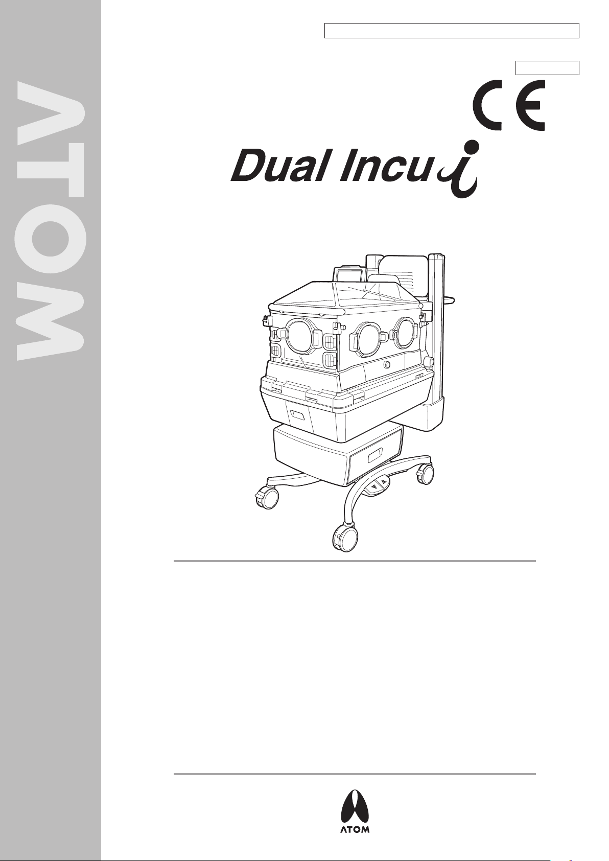
Atom Infant Incubator Model 100
Service Manual & Parts List
ORIGINAL
TO THE OPERATOR AND THE PERSON IN CHARGE OF
MAINTENANCE AND CARE OF THE UNIT:
This Manual describes var ious inspections needed to ensure proper operation
of the Dual Incu i, including instructions for troubleshooting, those procedures
to change certain settings which are not mentioned in the Operation Manual,
and important points to bear in mind when handling the unit.
Various inspections, including periodical inspection, are described in detail in
this Manual. They should be carried out only by those who are fully familiar
with the operation of the unit, having adequate technical knowledge and skills
required in inspecting the unit.
If repairs seem to be required as a result of any inspection described in this
Manual, either personnel with more advanced knowledge and skills should
undertake the repair or you should contact your local Atom representative
for repair service.
Page 2

Via F. Croce, 65 - 20081 Abbiategrasso (MI) - Italy
Tel: +39 02 99763101 Fax: +39 02 99763110
EU OFFICE
Page 3

INTRODUCTION
This Service Manual describes procedures for inspecting, repairing and changing the settings of the Dual Incu i.
It also describes precautions and troubleshooting in alarm conditions. The procedures described in this Ser vice
Manual should be carried out only by personnel trained in electricity and the operation of the unit. Neither Atom
Medical Corporation nor its representative will be responsible for the quality and performance of the unit if the
unit should not be handled as instructed or if unauthorized parts should be used in repairs. It should be noted
that any responsibility arising from inspecting, repairing or changing the settings of the unit lies with the person
who carried it out.
Read this Ser vice Manual carefully and familiarize yourself thoroughly with its contents before inspecting, repairing
or changing the settings of the unit. Keep this Manual where it is readily accessible for reference when needed.
For more detailed information on inspecting, repairing and changing the settings of the unit, contact your local
Atom representative.
Read the Operation Manual thoroughly before using the Service Manual.
SAFETY INFORMATION
Please read the Manual carefully before operating the unit. Please follow the instructions when operating the
unit.
Basic Instructions
1. Medical institutions are responsible for the maintenance, inspection and care of the unit.
2. When you choose to have the unit maintained and inspected or when the unit is found to be in need of
repairs from the results of inspection, consult your local Atom representative and take one of the following
measures.
1) Ask someone who has completed a training course specified by Atom and who has sufficient technical
knowledge and skills to do the work.
2) Ask Atom to send its service engineer if a person who has completed a training course specified by Atom
and who has sufficient technical knowledge and skills is not available.
3) Ask Atom for its approval of returning the unit for repair service.
3. Follow the instructions for safety.
Read the operating precautions thoroughly before operating the unit.
4. Inspect the unit on a periodical basis.
Periodical inspection is needed to use the unit in the optimum condition.
5. Ensure that the unit will not be used if it is found to be defective.
Take proper measures to ensure that a defective unit will not be used by mistake before it is properly inspected,
repaired and has its settings changed for normal operation. Such measures include indicating on the unit that
it is under inspection/repair and keeping it away from other devices that function correctly.
1
Page 4
2
Definitions of Warning Indication
DANGER:
WARNING
:
CAUTION:
Three levels of warning indication are used throughout this Service Manual & Parts List and on the unit.
They are defined as follows.
A DANGER notice indicates an immediately hazardous situation which, if not avoided,
will result in death or serious injury, serious damage to property such as total loss of use
of equipment, or fire.
A WARNING notice indicates an indirectly (potentially) hazardous situation which,
if not avoided, will result in death or serious injury, serious damage to property such as
total loss of use of equipment, or fire.
A CAUTION notice indicates a hazardous situation which, if not avoided, can result in
minor or moderate injury, partial damage to equipment, and loss of data stored
in computers.
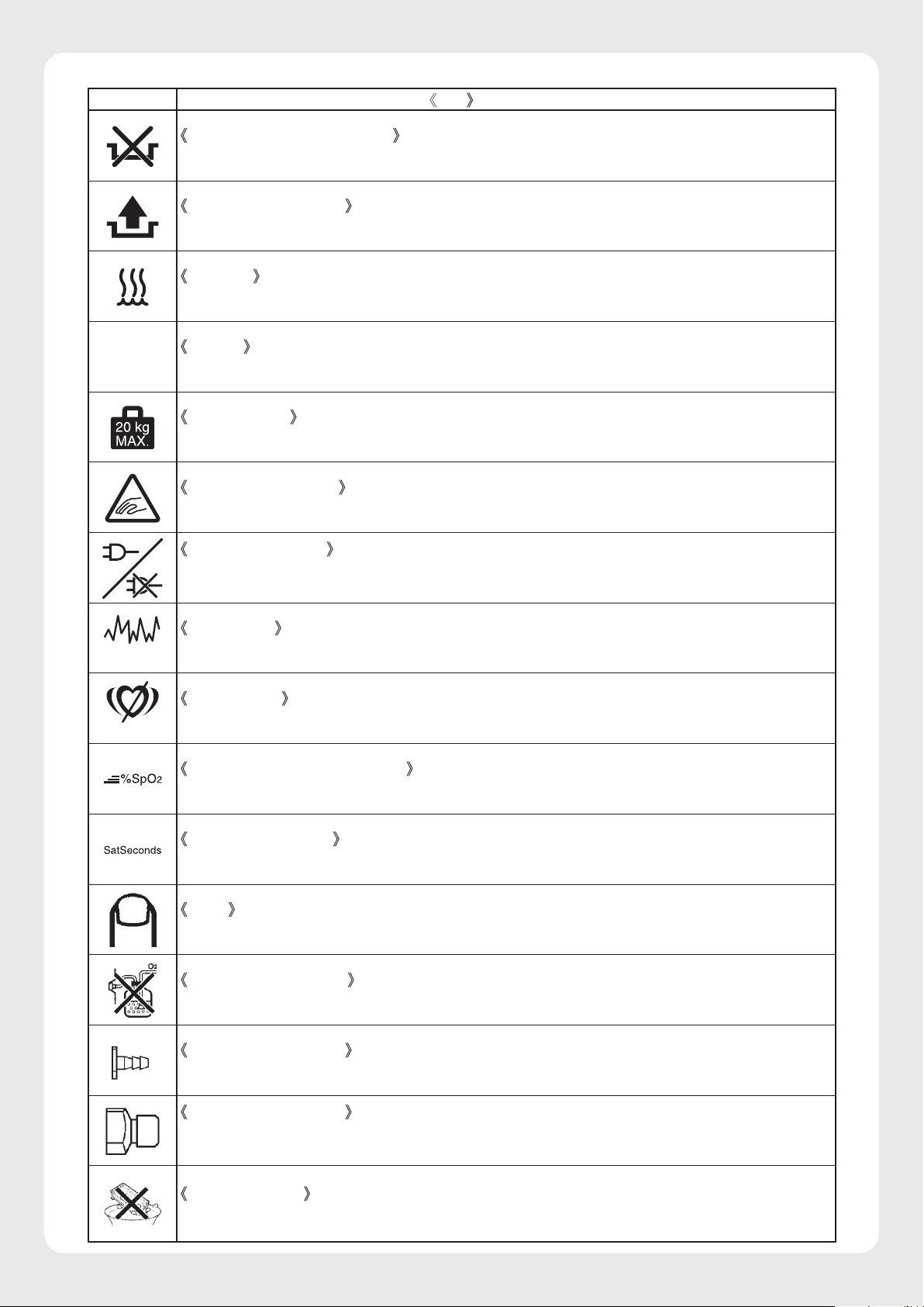
Definition of Symbols
1. Symbols to indicate danger, warning or caution
Symbol Title and indication
General attention
Indicates unspecified general danger, warning or caution.
Caution: Hot surface
Indicates that the surface can be dangerously hot under certain conditions.
2. Symbols to prohibit action
Symbol Title and indication
General prohibition
Indicates unspecified general prohibition.
Prohibition of disassembly
Indicates prohibition of disassembly of the unit where it may cause an electric shock or other
hazards.
Prohibition of use of fire
Indicates prohibition of use of fire where an external use of fire may cause the unit to ignite under
certain conditions.
3. Symbols to give instructions for action
Symbol Title and indication
General instruction
Indicates unspecified general action on the part of the user.
Connect a ground wire
Instructs the user to connect the ground wire without fail where the unit is provided with a ground
terminal.
Remove the power plug from the power outlet
Instructs the user to remove the power plug from the power outlet in the case of malfunction or
when there is a threat of lightning.
Page 5
3
4. Symbols of international standards (IEC)
Symbol Title and indication
Power on
Indicates in relation to the power switch that the device is connected to the power source.
Power off
Indicates in relation to the power switch that the device is not connected to the power source.
Equipment partially on
Indicates that a part of the device is “ON.”
Equipment partially off
Indicates that a part of the device is “OFF.”
Type BF applied part
Indicates that the device is classified as Type BF in terms of the degree of protection against an
electric shock.
Bell silenced
Indicates either a control switch to silence the bell permanently or temporarily, or that the bell is
silenced.
Date of manufacture
Indicates the date when the unit was manufactured in the factory.
Recyclable (battery)
Indicates that recycling is recommended.
WEEE symbol
In the EC area, an electrical and electronic product falling in one of the categories specified by
“DIRECTIVE 2002/96/EC OF THE EUROPEAN PARLIAMENT AND OF THE COUNCIL of 27
January 2003 on Waste Electrical and Electronic Equipment (WEEE)” should be disposed of in a
manner consistent with relevant laws and regulations.
This symbol indicates that the above-mentioned requirement applies to this product.
Locked
Indicates a locked condition.
Unlocked
Indicates an unlocked condition.
Manufacturer
This symbol indicates the name and the address shown adjacent to the symbol is of the manufacturer.
Authorised representative in the european community
This symbol indicates the name and the address shown adjacent to the symbol is of the authorised
representative in the European Community.
Page 6
4
5. Other symbols
Symbol Title and indication
Setting
Indicates that a setting is increased.
Setting
Indicates that a setting is decreased.
Main screen display switch
Indicates a switch to display the main screen.
Trend screen display switch
Indicates a switch to display the trend screen.
Menu screen display switch
Indicates a switch to display the menu screen.
Pulse oximeter screen display switch
Indicates a switch to display the pulse oximeter screen or the function related to the pulse rate.
Weight screen display switch
Indicates a switch to display the weight screen or the function related to weighing the infant.
Battery
Indicates whether the incubator is being powered by a battery or not.
Incubator air circulation
Indicates the function related to air circulation in the incubator in the incubator mode or that the
incubator is in manual control.
Radiant warmer
Indicates the heater output in the radiant warmer mode or that the radiant warmer is in manual
control.
Setting
Indicates set values or the setting procedure.
Skin temperature
Indicates the function related to the infant’s skin temperature or that the incubator is in servo
control.
Temperature
Indicates, with this symbol alone or with other symbols, a detected temperature or a set temperature alarm.
Peripheral temperature
Indicates the function related to the infant’s peripheral temperature (skin temperature 2).
Low water level/no water
Indicates that there is little or no water in the humidity chamber.
Page 7
5
Symbol Title and indication
O2
(Nellcor)
(Nellcor)
Defective humidity chamber
Indicates that something is wrong with the humidity chamber.
Humidity chamber off
Indicates that the humidity chamber is not attached properly.
Humidity
Indicates the function related to humidity.
Oxygen
Indicates the function related to oxygen.
Load capacity
Indicates the maximum load capacity.
Avoid getting caught
Indicates that the user must avoid getting caught in the gap in the device.
AC power indicator
The indicator lamp comes on in green when the unit is connected to the AC power source. It comes
on in red when no power is supplied to the unit.
Interference
Indicates that interference exists.
Pulse search
Indicates that no pulse is detected.
Fast response mode indicator
Indicates that the response mode of the pulse oximeter is set to “Fast.”
SatSeconds display
Displays the selected SatSeconds alarm limit setting.
Press
Indicates that the lock function will be released when the key with this symbol is pressed.
No humidified oxygen
Indicates that humidified oxygen must not be supplied.
Oxygen supply port 1
Indicates the oxygen supply port when oxygen is supplied through the flowmeter.
Oxygen supply port 2
Indicates the oxygen supply por t for the piping connecting hose when the oxygen controller is
used.
Do not immerse
Indicates that the humidity chamber must not be immersed in water.
Page 8

CONTENTS
INTRODUCTION .................................................... 1
PLEASE READ WITHOUT FAIL
[1] Operating Precautions .............................. 8
1-1. DANGER ............................................. 8
1-2.
1-3.
WARNING ........................................... 9
CAUTION .......................................... 11
[2] Parts Identification ................................... 14
2-1. Main body ................................................. 14
2-2. Display ....................................................... 17
2-3. Display Screens ....................................... 18
2-3-1. General Description of the
Screens ...................................... 18
2-3-2. Screen Transition Diagram ...... 21
2-3-3. List of Operations Available on
Each Screen .............................. 22
2-3-4. Main screen ............................... 23
2-3-5. Pulse Oximeter Screen ............ 28
2-3-6. Weight Screen ........................... 33
2-3-7. Menu Screen ............................. 36
2-3-8. Trend Screen ............................. 40
2-4. Service Menu (How to Operate the
Service Menu Screen) ........................... 42
2-4-1. How to Enter the
Service Menu ............................ 42
2-4-2. Operating the Service Menu
Screen ........................................ 43
2-4-3. Calibrating the Touch Panel .... 47
MAINTENANCE
[3] Maintenance Inspection.......................... 49
3-1. Inspection before Use ............................. 50
3-1-1. Visual Inspection ...................... 50
3-1-2. Functional Inspection ............... 52
3-1-3. Performance Inspection ........... 55
3-1-4. Checking and Calibrating the
Weight Monitor .......................... 56
3-2. Quarterly Inspection ................................ 57
3-3. Inspection Checklist ................................ 58
3-4. Periodical Replacement Parts and
How to Replace them ............................. 59
3-4-1. Replacing the Filter................... 60
3-4-2. Replacing the Oxygen
Sensor ........................................ 61
[4] Cleaning and Disinfection ...................... 63
4-1. Hood Assembly ........................................ 64
4-2. Mattress Platform and Parts Beneath... 67
4-3. Heater for Radiant Warmer .................... 69
4-4. Humidity Chamber ................................... 69
4-5. Others ........................................................ 70
[5] Troubleshooting ........................................ 71
5-1. Alarms ....................................................... 71
5-2. Troubleshooting ....................................... 77
5-3. Troubleshooting Flowchart ..................... 79
5-3-1.
5-3-2. Troubleshooting When the Unit
Troubleshooting When the Unit
Cannot Be Controlled Properly
Does Not Function Properly .... 80
... 79
DISSASSEMBLY AND REPLACEMENT
[6] Disassembly and Replacement
Procedures ............................................... 108
6-1. Stand ....................................................... 108
6-1-1. Removing the Main Body from
the Stand .................................. 108
6-1-2. Replacing the Hi-Low Stand
Actuator ................................... 111
6-1-3. Replacing the Foot Switch..... 112
6-1-4. Replacing the Relay Board for
Foot Switch. ............................. 113
6-1-5. Replacing the Caster .............. 114
6-1-6. Replacing the Radiant Warmer
(with F-rail Pole, Height
Adjustment Unit) ..................... 114
6-1-7. Replacing Heater for Radiant
Warmer..................................... 116
6-1-8.
6-1-9. Replacing the F-Rail Pole
6-1-10. Replacing the Canopy
6-1-11. Replacing the Canopy ............ 121
6-1-12. Replacing the
6-1-13. Replacing the Hi-Low Drive
6-2. Hood ....................................................... 122
6-2-1. Replacing the Admittance
6-2-2. Replacing the Admittance
6-2-3. Replacing the Hood Cover
6-2-4. Replacing the Admittance
6-2-5. Replacing the Sensor Module
6-2-6. Replacing the Snap-open
6-2-7. Replacing the Admittance
6-2-8. Replacing the Admittance
6-2-9. Replacing the Admittance Panel
6-2-10. Replacing the Admittance Panel
6-2-11. Replacing the Inner Wall Lever
6-2-12. Replacing the Inner Panel
6-2-13. Replacing the Inner Wall
6-2-14. Replacing the Inner Wall Shaft
6-3. Main Body ............................................... 130
6-3-1. Removing the Upper Section of
Replacing the Disc-type Thermostat
for Radiant Warmer
Spacer ...................................... 118
(with Hi-Low Unit) ................... 119
Photomicroswitch .................... 121
Board ....................................... 122
Panel (Rear) ............................ 122
Panel (Front) ............................ 124
(Front) ....................................... 124
Panel Lock Holder .................. 125
Holder ....................................... 125
Access Port ............................. 126
Panel ........................................ 126
Panel Hinge ............................. 127
Operating Lever Right/Left .... 128
Operating Knob ....................... 128
Right/Left .................................. 129
Right/Left .................................. 129
Bearing ..................................... 130
Bearing ..................................... 130
the Main Body from the Main
Body .......................................... 130
.................... 117
Page 9

PLEASE READ WITHOUT FAIL
6-3-2. Replacing the Heater for the
Main Body ................................ 132
6-3-3. Replacing the Fan Motor ...... 133
6-3-4. Replacing the High Temperature
Sensor ...................................... 134
6-3-5. Replacing the Control Box
Cover ........................................ 135
6-3-6. Replacing the Switch Board .. 136
6-3-7. Replacing the Power Switch . 136
6-3-8. Replacing the Detection
Board ....................................... 137
6-3-9. Replacing the Tilting Unit ....... 137
6-3-10. Replacing the Position Detection
Board (for the Detection of the
Middle Board) .......................... 138
6-3-11. Replacing the Filter Joint ....... 138
6-3-12. Replacing the Humidity
Chamber Cover Packing ........ 139
6-3-13. Replacing the Humidity
Chamber Cradle ..................... 139
6-3-14. Replacing the Humidity
Chamber Cover ....................... 140
6-3-15. Replacing the Humidity
Chamber Cradle Packing ..... 140
6-3-16. Replacing the Humidity
Chamber Connector ............... 140
6-3-17. Replacing the Position Detection
Board (for the Detection of the
Boiler Cap) ............................... 141
6-3-18. Replacing the Position Detection
Board (for the Detection of the
Humidity Chamber Cover) ..... 141
6-3-19. Replacing the Control Power
Transformer ............................. 142
6-3-20. Replacing the Drive Power
Transformer ............................. 143
6-3-21. Replacing the Oxygen
Controller.................................. 143
6-3-22. Replacing the Mass Flow
Valve ......................................... 144
6-3-23. Replacing the Solenoid
Valve ......................................... 145
6-4. Power Unit ............................................... 146
6-4-1. Replacing the Main Board ..... 146
6-4-2. Replacing the Battery for
Power Failure Alarm ............... 147
6-4-3. Replacing the Heater Control
Board ........................................ 148
6-4-4. Replacing the AC Inlet .......... 150
6-4-5. Replacing the Buzzer ............. 150
6-4-6. Replacing the Noise Filter ..... 151
6-4-7. Replacing the Hi-Low Drive
Board ........................................ 151
6-4-8. Replacing the Rectifier
Board ........................................ 152
6-4-9. Replacing the Circuit
Breaker ..................................... 152
6-4-10. Replacing the Insulating Board
for SpO
6-5. Display ..................................................... 154
6-5-1. Replacing the F-Rail Arm ...... 154
Unit ......................... 153
2
6-5-2. Replacing the Cable Guide ... 154
6-5-3. Replacing the Front Panel ..... 155
6-5-4. Replacing the Rear Panel
(with Alarm Lamp) .................. 156
6-5-5. Replacing the LCD Display ... 157
6-5-6. Replacing the Speaker .......... 158
6-5-7. Replacing the Alarm Lamp
Board ........................................ 159
6-5-8. Replacing the Power Indicator
Board ........................................ 160
6-5-9. Replacing the LCD Display
Board ........................................ 160
6-5-10.
6-5-11. Replacing the Button Cell
6-5-12. Replacing the Connector
6-6. Mattress Platform ................................... 163
6-6-1.
6-6-2. Replacing the Latch ............... 164
6-6-3. Replacing the Weight Monitor
Replacing the CCFL Inverter
Battery for the Display ............ 162
Cap ........................................... 162
Replacing the Baby Guard (Front/
Rear)/Baby Guard (side)
Module ...................................... 164
... 161
............ 163
INFORMATION
[7] Electrical Block Diagram ..................... 165
[8] Wiring Diagram........................................ 166
8-1. Drive Unit ................................................ 166
8-2. Main Body ............................................... 167
8-3. Peripheral Units ...................................... 168
[9] Parts List ................................................... 169
9-1. Fig-1 Main Body and Accessories ....... 170
9-2. Fig-2 Display ........................................... 172
9-3. Fig-3 Humidity Chamber....................... 174
9-4. Fig-4 Mattress Platform ......................... 176
9-5. Fig-5 Upper Section of the
Main Body 1 .......................................... 178
9-6. Fig-6 Upper Section of the
Main Body 2 .......................................... 180
9-7. Fig-7 Upper Section of the
Main Body 3 .......................................... 182
9-8. Fig-8 Lower Section of the
Main Body .............................................. 184
9-9. Fig-9 Power Unit .................................... 186
9-10. Fig-10 Oxygen Controller Assembly .... 188
9-11. Fig-11 Upper and Lower Sections of the
Main Body and Filter Case Assembly 190
9-12. Fig-12 Stand .......................................... 192
9-13. Fig-13 Stand ........................................... 194
9-14. Fig-14 Canopy ........................................ 196
9-15. Fig-15 Pulse Oximeter (Masimo) ......... 198
9-16. Fig-16 Pulse Oximeter (Nellcor) .......... 200
APPENDIX
[10] Technical Information ............................ 202
10-1. Technical Data ........................................ 202
10-2. EMC Level and Classification .............. 208
[11] Disposal .................................................... 212
MAINTENANCE
DISASSEMBLY AND REPLACEMENT
INFORMATION APPENDIX
Page 10

8
Operating Precautions
Operating Precautions[1]
Please follow the operating instructions described in this Service Manual & Parts List for the safe use of the
unit. The unit should be operated only by those who have been trained and instructed properly in its operation.
The unit should be operated only for its intended use.
1-1. DANGER
Death or serious injur y, damage to equipment or a fire will result if the instr uctions given below are not followed.
Only those who have been properly trained should operate the unit.
Be sure to keep the admittance panels and the access ports closed when the unit is in use.
Using the unit with an admittance panel or an access port left open may cause the infant to fall out of
the baby compartment. Be sure to close the admittance panels and the access ports when performing
phototherapy on an infant inside the incubator.
Monitor the infant’s skin temperature when operating the unit.
If the incubator air temperature should rise during phototherapy, proceed with the phototherapy
in the radiant warmer mode or after placing the infant in a cot or an open-type incubator (an
infant warmer), as directed by the doctor.
Since a mature infant emits much heat, the incubator air temperature may rise if you place the infant
in the incubator and perform phototherapy. The incubator air temperature may also rise if you use
multiple phototherapy units at the same time or if the room temperature is high. In such a case, proceed
with the phototherapy in the radiant warmer mode or after placing the infant in a cot or an open-type
incubator, as directed by the doctor. Take sufficient care when using a cot, as it becomes dif ficult to
observe the infant. Alternatively, placing an ice bag inside the incubator has the effect of decreasing
the incubator air temperature.
However, be sure to close the admittance panels and the access ports in this case also.
Do not leave the unit unattended when an admittance panel or an access port is open.
If an admittance panel or an access por t is left open, the infant may fall out of the baby compartment
and get fatally injured. Never leave the unit unattended when an admittance panel or an access por t
is open.
Stop using the unit immediately and seek repair if an admittance panel, a snap-open access
port or a press lever should be found loose or faulty in any way.
The infant may fall out of the baby compartment.
Never place a body warmer or any other possible ignition source in or near the unit.
Use of oxygen will increase the risk of explosion or fire. Body warmers or other devices in which fire
is used or which will generate a spark may cause an explosion or a fire if used near the unit.
Do not use the unit in the presence of a flammable anesthetic gas.
The unit may cause an explosion or a fire if used in the presence of such a gas.
Page 11

9
PLEASE READ WITHOUT FAIL
Operating Precautions
Do not use ether, alcohol or any other ignitable substance.
Even a small amount of ether, alcohol or other ignitable substances may cause a fire when mixed with
the oxygen in the incubator.
Do not hang any flammable materials on the radiant warmer.
It may cause a fire.
Ground the unit securely.
Otherwise, a leakage current may cause an electric shock. In order to complete the ground connection,
connect the power cord only to a properly grounded 3P power outlet including a ground terminal. Do
not operate the unit if you have any doubt about its ground connection.
Do not use a device generating high frequency near the unit.
To prevent malfunction of the unit due to jamming, do not use electric surgical knives, portable and
mobile communication equipment and other devices which generate high frequency near the unit
during its operation.
Analyze arterial gas levels repeatedly when a high oxygen environment is required.
When the infant requires a high oxygen environment, it is extremely important and essential to periodically analyze ar terial gas levels in order to maintain the desired oxygen concentration in the incubator.
Follow the doctor’s instructions in measuring the oxygen concentration because ignoring essential
requirements may increase the risk of retinopathy of prematurity and other adverse ef fects.
Do not give a shock to the unit or let it hit anything.
The screws or fixed parts may become loose.
The heaters are consumables. If the heaters are to be used beyond their expected life span,
overall repairs including replacement of parts must be carried out.
1-2. WARNING
Death or serious injury due to a fire or an electric shock will result if the instructions given below are not followed.
Be sure to follow the doctor’s instructions in setting the incubator air temperature or the
infant’s skin temperature.
Be sure to follow the doctor’s instructions in setting the relative humidity in the incubator.
Be sure to follow the doctor’s instructions in supplying oxygen.
Be sure to follow the doctor’s instructions in setting the oxygen concentration in the incuba-
tor.
Use only oxygen for medical use.
Page 12

10
Operating Precautions
Be sure to bear in mind the following precautions during oxygen supply.
• Do not place a body warmer, a ashlight, oils and fats, or ammable vaporizable matters in the
incubator.
• Use pure cotton for the infant’s clothing, bed sheets, etc. Do not use any material that is easily
charged with static electricity.
• Use pure cotton or re-proof materials for the clothing of doctors, nurses and ambulance staff who
handle this unit.
Bear in mind the following precautions while using oxygen supply equipment.
• If oil, grease or a grease-like substance should get in contact with pressurized oxygen, a violent
spontaneous ignition may occur. Do not let such substances stick to the oxygen pressure regulator,
the oxygen cylinder valve, piping, connections and other parts of oxygen supply equipment.
• On a high-pressure oxygen cylinder, use only a tested pressure reducing valve or pressure regulating valve indicated specifically for oxygen supply. Do not use such a valve for any gas other than air
or oxygen. It is dangerous to use a valve to supply a gas other than air or oxygen and then to supply
oxygen again.
If the oxygen sensor should break or get damaged, the electrolyte inside may leak out of
the sensor. If you should come in contact with the electrolyte, wash it away immediately and
thoroughly with copious amounts of water.
Smoking is prohibited in the room where the unit is installed.
Do not place any possible ignition sources in the room.
Avoid damaging the power cord.
A damaged power cord may cause a fire or an electric shock.
• Do not get the power cord caught between the unit and the wall, a shelf or the oor.
• Do not place the power cord near a heating apparatus or heat it.
• Do not put anything heavy on the power cord.
• Always grasp the power plug with your hand to remove the power cord from the power outlet. A
damaged power cord should be replaced immediately with a new one.
Use only the power cord supplied with the unit.
Otherwise, a fire or an electric shock may result.
Before cleaning and disinfecting the unit, be sure to turn the power switch off, remove the
power plug, and allow the incubator air temperature and the heater temperature to drop suf-
ficiently.
Do not touch the power plug with a wet hand.
Touching the power plug with a wet hand may cause an electric shock.
Do not touch the heaters during use or shortly after use.
The heaters are so hot during use and shortly after use that you may get burned. Allow the heaters to
cool down sufficiently before touching them.
Do not disassemble or modify the unit.
Disassembling or modifying the unit may cause a fire, an electric shock or injury.
Page 13

11
PLEASE READ WITHOUT FAIL
Operating Precautions
Do not install the unit where it will be exposed to excessive humidity, dust or steam.
Installing the unit in such a place may cause a fire or an electric shock.
The power outlet should be located near the unit to prevent accidental contact with a trailing
power cord. Use a separate power outlet for each unit.
Do not put many loads on one power outlet.
In order to complete the ground connection, connect the power cord only to a properly
grounded 3P power outlet including a ground terminal.
Do not operate the unit if you have any doubt about its ground connection.
Ground peripheral electric equipment securely.
Never connect the unit to a power outlet other than that specified.
The unit should be serviced only by qualified personnel.
Be sure to inspect the unit at the start of each day.
Operating the unit without inspecting it at the start of each day may let a defect pass unnoticed and
cause a potentially unfavorable outcome.
Check for conformity to the applicable standard if the unit is going to be connected to another
medical device for use as a system.
Accessory equipment connected to the analogue and digital interfaces must comply with the relevant
IEC standards (e.g. IEC 60950 for data processing equipment). Furthermore all configurations should
comply with IEC 60601-1-1. But the items that are not specified as part of the system should not be
connected. Anybody who connects additional equipment to the signal input or signal output configures
a medical system, and therefore should make the medical system comply with the requirements of
60601-1-1 on his or her own responsibility. If in doubt, consult your local Atom representative.
1-3. CAUTION
Injury or damage to surrounding objects may result if the instructions given below are not followed.
Be sure to clean and disinfect the unit before using it for the first time after purchase.
The unit is shipped without being disinfected.
During standby in the incubator mode, be sure to always preheat the unit in order to keep
the incubator air temperature stable.
During standby in the radiant warmer mode, be sure to always preheat the unit in order to
keep the mattress surface temperature stable.
Place the infant in the incubator only after the incubator air temperature has stabilized.
Page 14

12
Operating Precautions
When feeding the cords and tubes into the unit, be very careful not to let them wind or tighten
around the patient.
Do not hang any cables or infusion tubes on the canopy or the canopy arm. Do not pass
them above the canopy.
Do not twist or pull the cords by force.
If any defect should be found, ask an expert for repair without attempting to repair it yourself.
Remove the power plug from the power outlet before moving the unit to another place or
when the unit is not going to be used for a long time.
Moving the unit to another place with the power plug connected to the power outlet will damage the
power cord and may cause a fire or an electric shock.
Remove the power plug from the power outlet before cleaning and disinfecting the unit.
Cleaning and disinfecting the unit with the power plug connected to the power outlet may cause an
electric shock.
Install the unit on a stable surface.
Installing the unit on an unstable platform or a tilted surface will cause it to fall or drop and may injure
someone. Therefore, before installing the unit, make sure that the place where the unit is to be installed
is stable and strong enough to support the weight of the unit.
Install the unit out of reach of small children.
Do not operate the radiant warmer covered with a cloth, etc.
Operating the unit covered with a cloth or pressed tightly against a wall may cause a fire or an electric
shock due to overheating.
When performing phototherapy on the infant in the incubator, pay special attention to the
infant’s skin temperature and the incubator air temperature during the treatment.
The infant’s skin temperature and the incubator air temperature may rise due to the radiant heat
generated by the phototherapy unit.
Do not install the unit in direct sunlight or near a heating apparatus.
Do not expose the unit to extraordinarily high temperature or excessive humidity.
Do not place anything heavy on the unit.
Do not place anything on the canopy.
Do not lean on the radiant warmer. Do not apply more force than is necessary to the radiant
warmer.
Do not press strongly or rub the operation panel of the display.
Pressing it strongly or rubbing it may damage the display or cause it to malfunction.
Page 15

13
PLEASE READ WITHOUT FAIL
Operating Precautions
Be careful not to let any medical fluid adhere to the display.
Do not attach any peripheral device that is not specified by Atom to the incubator.
Check the operation of the peripheral devices.
If a device transmitting or receiving weak signals is installed near the unit, it may be affected by the
electromagnetic waves generated by the latter. Check the operation of the peripheral devices for
any effect before using the unit in clinical settings. Stop using the unit immediately if any trouble is
detected.
When relocating the unit, watch your step so that you do not have your feet run over by a
caster.
Page 16
14
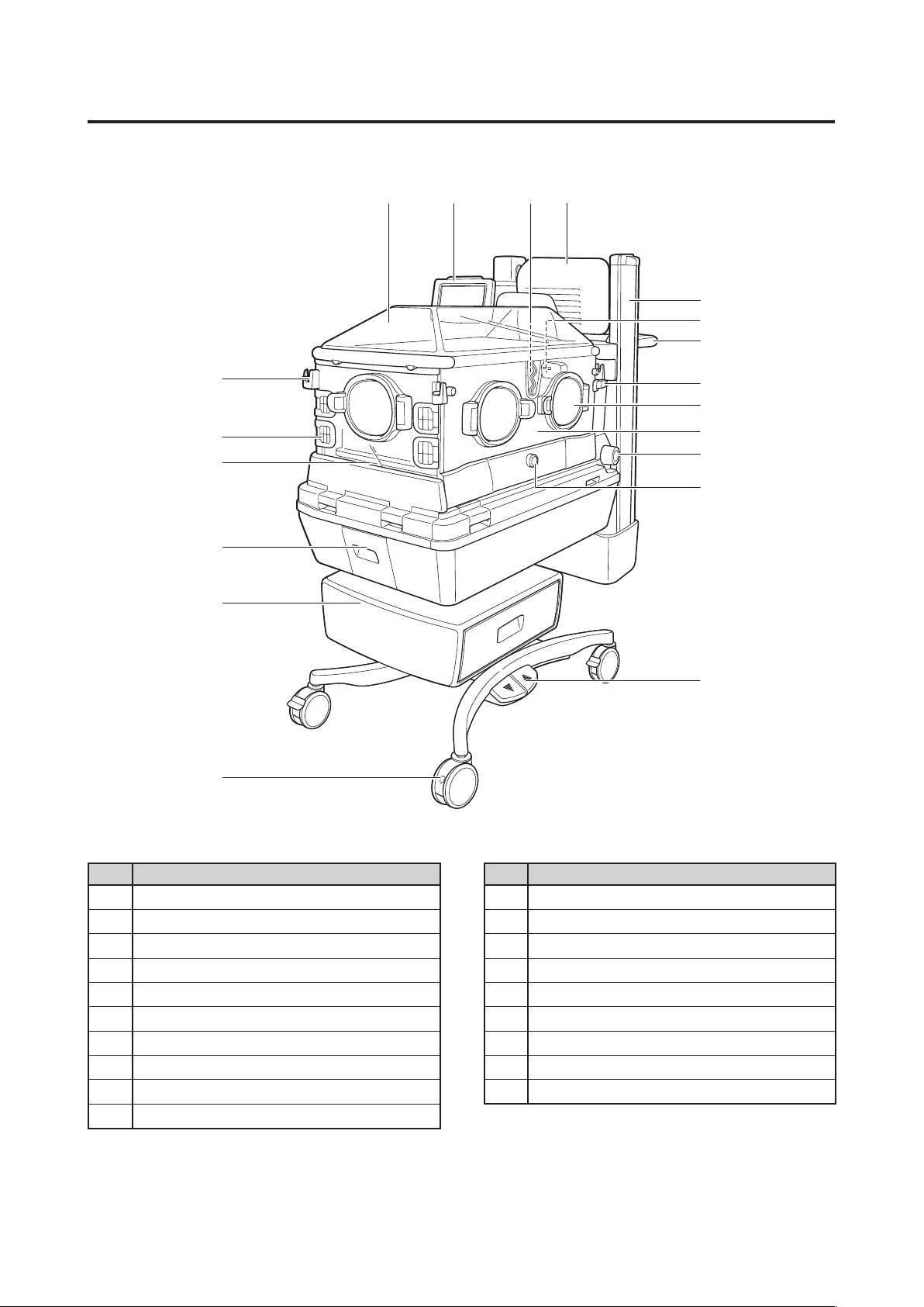
Parts Identification
⑲
①
②
⑤
⑧
⑨
⑪
⑬
⑩
⑫
③④
⑱
⑰
⑯
⑮
⑭
⑥
⑦
Parts Identification[2]
Main body2-1.
No. Name No. Name
Canopy
①
Display
②
Patient circuit slot grommet
③
Radiant warmer
④
Dovetail rail
⑤
Sensor module
⑥
Handle
⑦
Admittance panel operating lever
⑧
Snap-open access port
⑨
Admittance panel
⑩
Mattress platform tilting knob
⑪
X-ray cassette tray door locking knob
⑫
Foot switch
⑬
Caster
⑭
Drawer
⑮
Humidity chamber cover
⑯
Mattress
⑰
Tube introduction slit packing
⑱
Admittance panel operating knob
⑲
Note: ⑮ Drawer is an available option.
Page 17
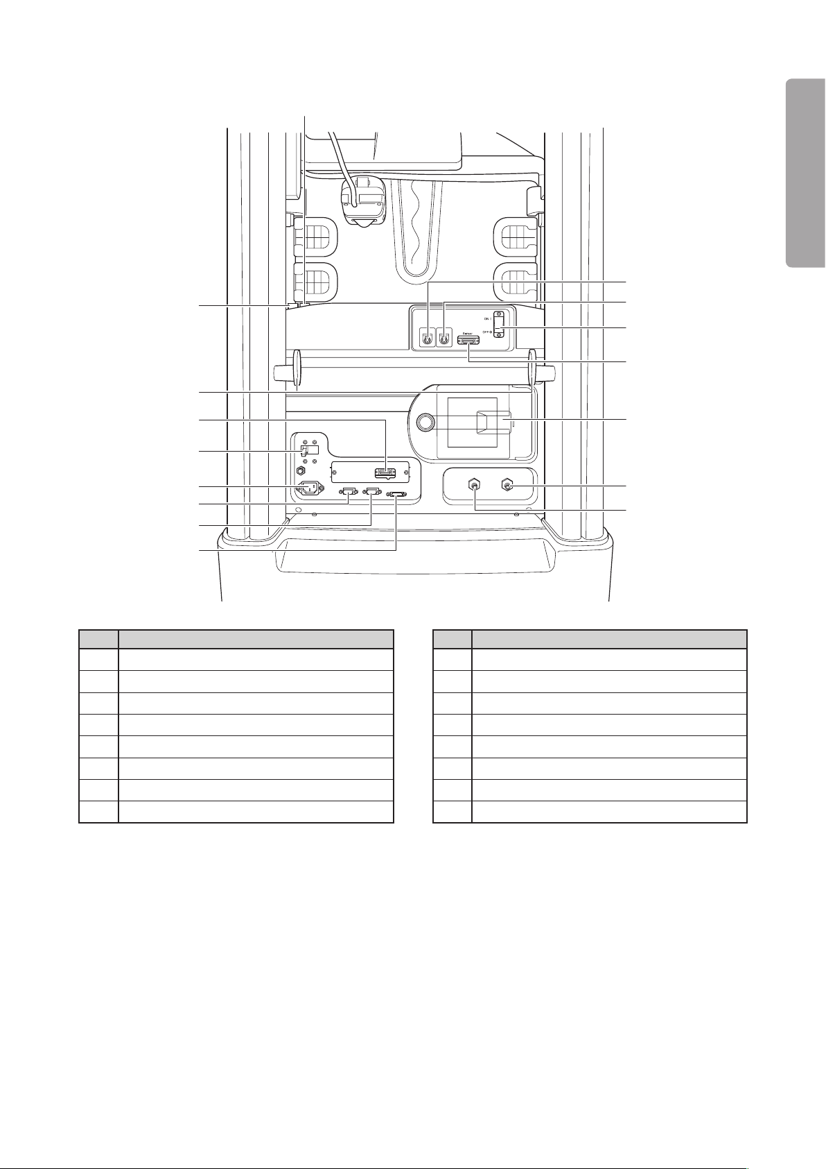
15
PLEASE READ WITHOUT FAIL
Parts Identification
⑳
Rear
No. Name No. Name
⑳
Incubator mode switch
Radiant warmer mode switch
Skin temperature probe connecting port 1
Skin temperature probe connecting port 2
Power switch
Connector for sensor module
Filter cover
Oxygen supply port 1
Note: Oxygen supply por t 2 is available only on the unit equipped with the oxygen controller.
Connector for SpO
2 is an available option.
Oxygen supply port 2
Connector for weight monitor
Connector for the display
Connector for the Power Pack
AC inlet
Breaker
Connector for SpO
Cord cleat
2
i
(UPS)
Page 18
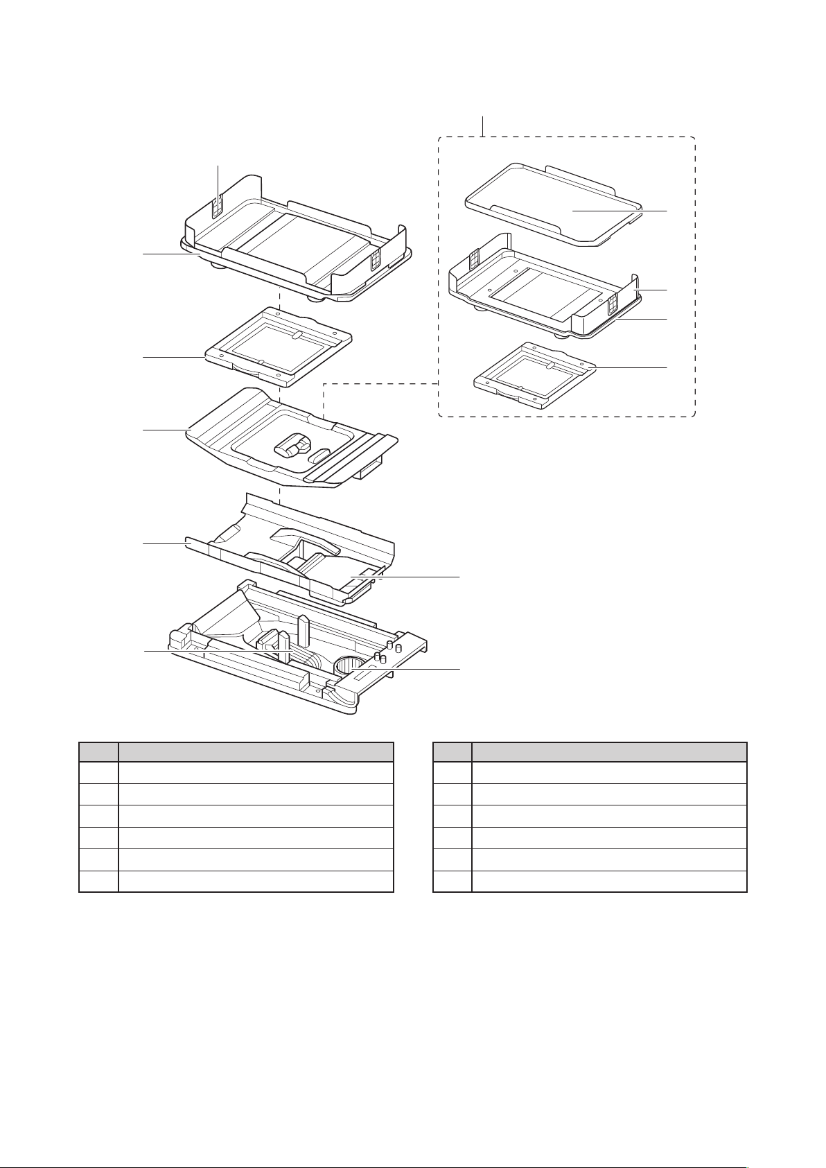
16
Parts Identification
Inside
No. Name No. Name
Mattress platform
X-ray cassette tray
Weight monitor unit
Mattress platform for weight monitor
Tray for weight monitor
Mattress platform tray
Middle board
Fan cover
Heater
Fan
Baby guard
Tube introduction slit packing
Note: Weight monitor unit is an available option.
Page 19
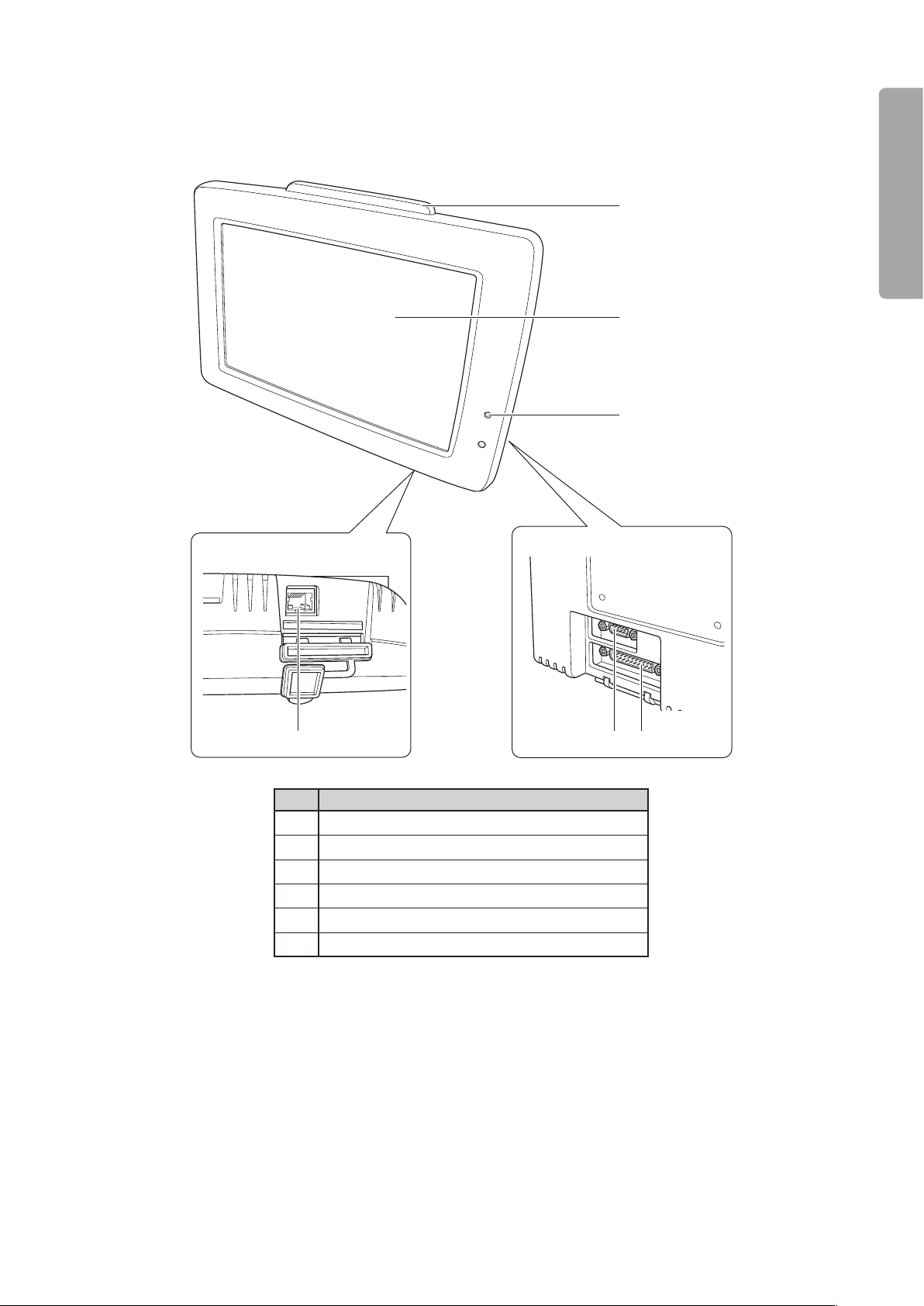
17
PLEASE READ WITHOUT FAIL
Parts Identification
Bottom
Rear
①
②
③
⑥
④⑤
Front
Display2-2.
No. Name
Alarm lamp
①
Operation panel
②
Power failure alarm indicator
③
I/O port (External communication connector)
④
Connector for the main body
⑤
Communication port (LAN)
⑥
Page 20
18
Parts Identification
Display Screens2-3.
General Description of the Screens2-3-1.
Start screen (This screen is displayed both in the incubator mode and in the radiant warmer mode.)(1)
The start screen appears when the power is applied.
It is automatically switched to the main screen of
the incubator mode if the canopy is in a lowered
position (the incubator mode); it is automatically
switched to the main screen of the radiant warmer
mode if the canopy is in a raised position (the radiant
warmer mode).
Incubator mode(2)
[Main screen]
This screen appears first when the unit enters the
incubator mode.
If any other screen of the incubator mode is being
displayed, touch the
will be displayed. This screen displays the set temperature, the incubator air temperature, the skin
temperature 1, the skin temperature 2, the relative
humidity, the oxygen concentration, SpO2, the pulse
rate, etc. in the incubator mode.
switch, and the main screen
[Pulse oximeter screen]
Touch the switch on any other screen of the
incubator mode, and the pulse oximeter screen of
the incubator mode will be displayed.
This screen highlights SpO2 and the pulse rate in the
incubator mode. Pulse waves are also displayed.
In addition, the set temperature, the incubator
air temperature, the skin temperature 1, the skin
temperature 2, the relative humidity, the oxygen
concentration, etc. are displayed.
[Weight screen] (
Touch the switch on any other screen of the
incubator mode, and the weight screen will be
displayed.
This screen highlights weight functions such as the
weighing procedure in the incubator mode and the
weight trend graph.
In addition, the set temperature, the incubator air
temperature, the skin temperature 1, the skin temperature 2, the relative humidity, the oxygen concentration, SpO2, the pulse rate, etc. are displayed.
This screen is displayed only when the unit is equipped with the weight monitor unit.
)
Page 21
19
PLEASE READ WITHOUT FAIL
Parts Identification
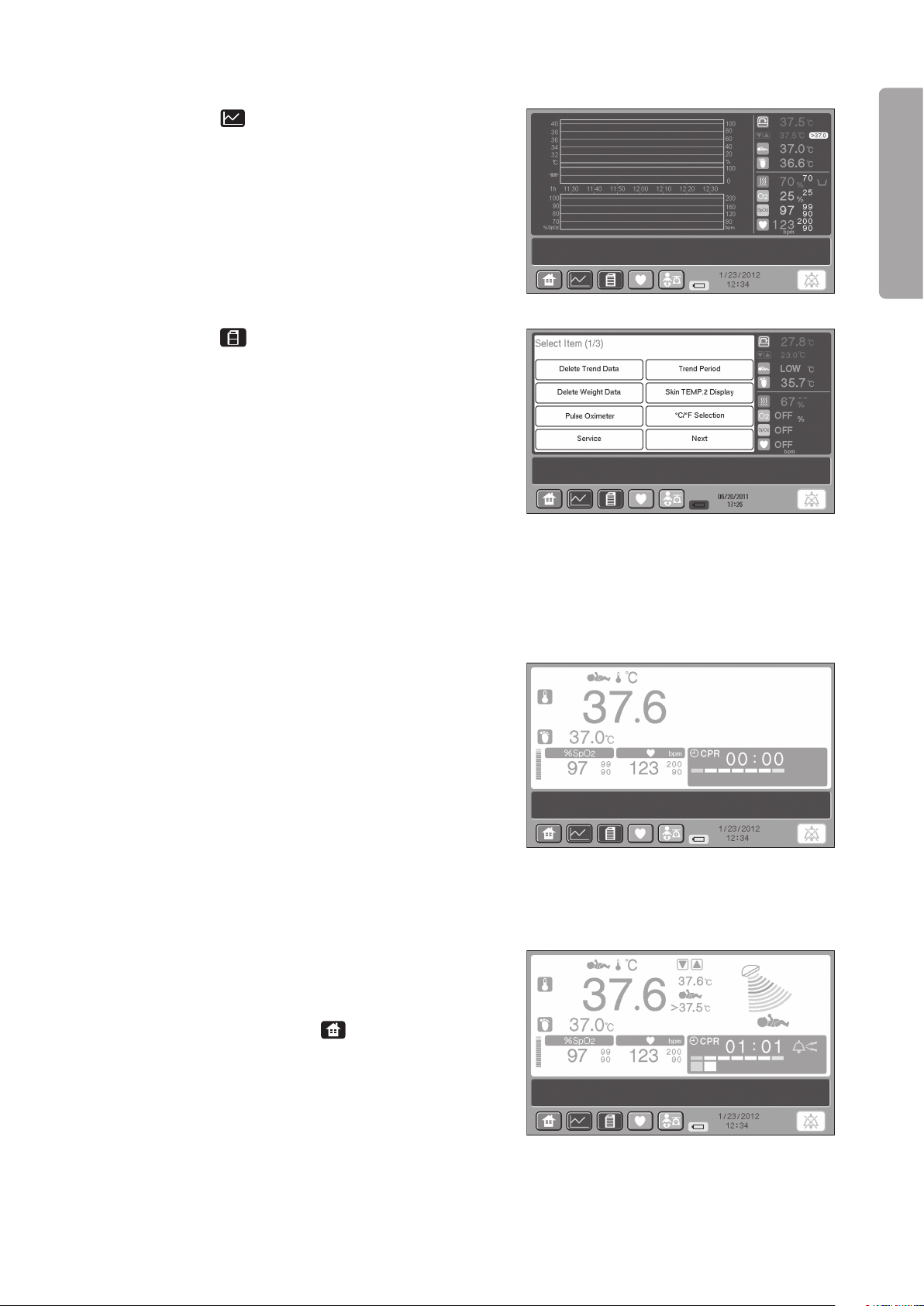
[Trend screen]
Touch the switch on any other screen of the
incubator mode, and the trend screen will be displayed.
This screen displays trend graphs.
[Menu screen]
Touch the switch on any other screen of the
incubator mode, and the menu screen for advanced
settings of the incubator mode will be displayed.
Use this screen to select advanced settings. In addition, the set temperature, the incubator air temperature, the skin temperature 1, the skin temperature
2, the relative humidity, the oxygen concentration,
SpO2, the pulse rate, etc. in the incubator mode are
displayed.
When this screen is displayed, you can only select
advanced settings of each menu item or switch the
screen to another.
Transition mode screen(3)
This screen appears during transition from the
incubator mode to the radiant warmer mode and
vice versa.
This screen displays such vital signs as the skin
temperature 1, the skin temperature 2, SpO
2, and
the pulse rate.
If the transition should be interrupted in emergency,
a message will appear on the screen. The mode cannot be switched on this screen.
Radiant warmer mode(4)
[Main screen]
This screen appears first when the unit enters the
radiant warmer mode.
If any other screen of the radiant warmer mode is
being displayed, touch the
switch, and the main
screen will be displayed.
This screen displays the heater setting, the heater
output, the skin temperature 1, the skin temperature
2, SpO2, the pulse rate, the timer, etc. in the radiant
warmer mode.
Page 22
20
Parts Identification
[Pulse oximeter screen]
Touch the switch on any other screen of the
radiant warmer mode, and the pulse oximeter screen
will be displayed.
This screen highlights the timer, SpO2, and the pulse
rate in the radiant warmer mode. Pulse waves are
also displayed.
In addition, the heater setting, the heater output,
the skin temperature 1, the skin temperature 2, etc.
are displayed.
[Weight screen] (
This screen is displayed only when the unit is equipped with the weight monitor unit.
Touch the switch on any other screen of the
radiant warmer mode, and the weight screen of the
radiant warmer mode will be displayed.
This screen highlights weight functions such as the
weighing procedure in the radiant warmer mode and
the weight trend graph.
In addition, the heater setting, the skin temperature
1, the skin temperature 2, SpO
2, the pulse rate, the
timer, etc. are displayed.
[Trend screen]
Touch the switch on any other screen of the
radiant warmer mode, and the trend screen will be
displayed.
This screen displays trend graphs.
)
[Menu screen]
Touch the switch on any other screen of the
radiant warmer mode, and the menu screen for
advanced settings of the radiant warmer mode will
be displayed.
Use this screen to select advanced settings. In addition, the set temperature, the skin temperature 1,
the skin temperature 2, SpO2, the pulse rate, etc. in
the radiant warmer mode are displayed.
When this screen is displayed, you can only select
advanced settings of each menu item or switch the
screen to another.
Page 23
21
PLEASE READ WITHOUT FAIL
Parts Identification
Incubator position
Radiant warmer position
Tr ansition potition
Tr ansition mode screen
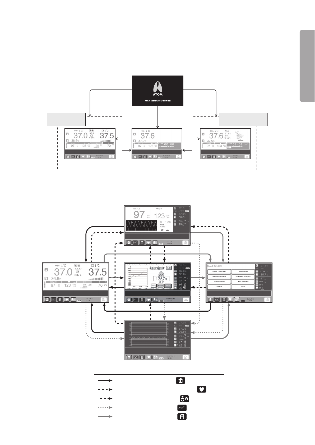
Start Screen
Main screen Main screen
Incubator mode Radiant warmer mode
✽
Power applied
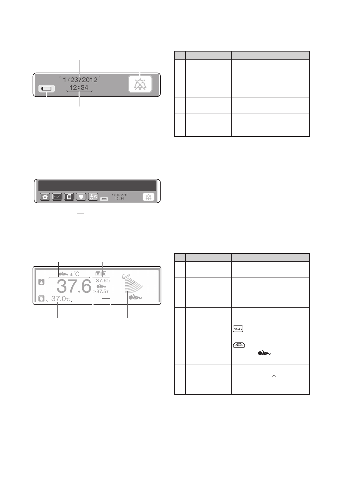
: [Main screen] display switch
: [Menu screen] display switch
: [Pulse oximeter screen] display switch
: [Trend screen] display switch
: [Weight screen] display switch
Main screen
Menu screen
Trend screen
Pulse oximeter screen
Weight screen
Screen Transition Diagram2-3-2.
Transition diagram between the two operation modes(1)
The start screen is automatically switched to the main screen of the incubator mode if the canopy is in a lowered
position (the incubator mode); it is automatically switched to the main screen of the radiant warmer mode if
the canopy is in a raised position (the radiant warmer mode).
Transition diagram in each operation mode(2)
The screens to be displayed in the incubator mode are shown below. The same transition diagram applies ✽
to the radiant warmer mode.
Page 24
22
Parts Identification
List of Operations Available on Each Screen2-3-3.
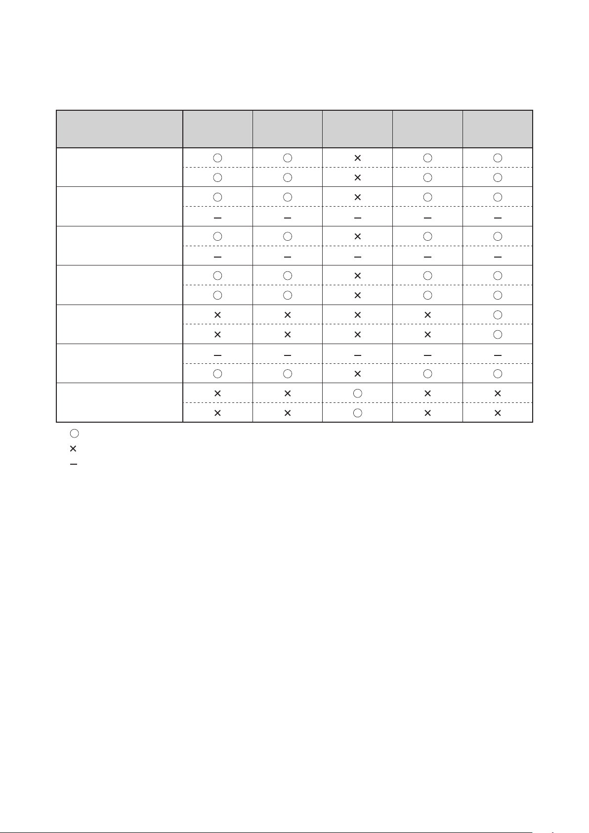
Table 1. List of Setting Operations Available on Each Screen
Upper: Incubator mode Lower: Radiant warmer mode
Setting (measuring)
Operation
Temperature-related
operation (manual/servo)
Setting humidity
Setting oxygen control
Setting SpO2/pulse rate
upper/lower alarm limits
Weighing the infant
✽2
Timer
✽1
Selecting other advanced
settings
Trend
screen
✽2
screen
Main
Menu
screen
Pulse
oximeter
screen
Weight
screen
✽1
: Setting (measuring) operation available
: Setting operation not available
: The function not provided
✽1: Optional function ✽2: Types selectable on the menu screen
Page 25
23
PLEASE READ WITHOUT FAIL
Parts Identification
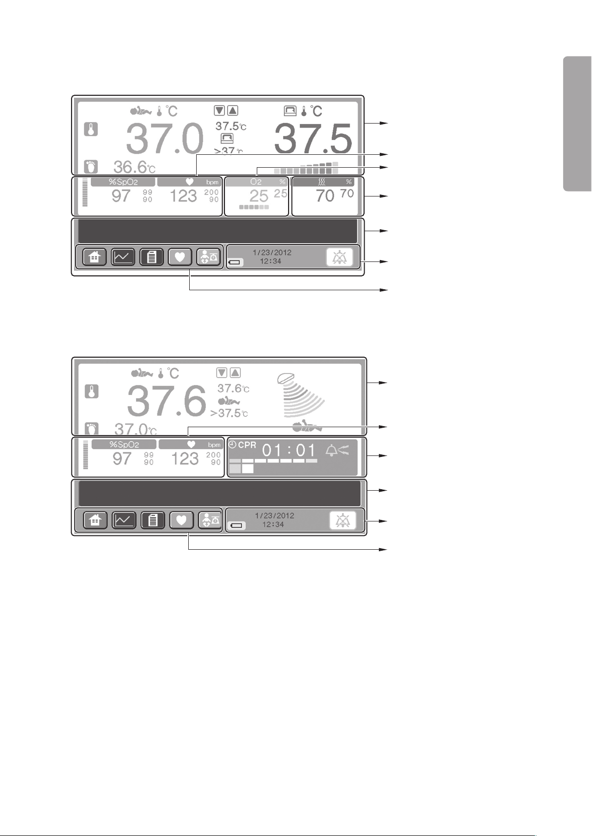
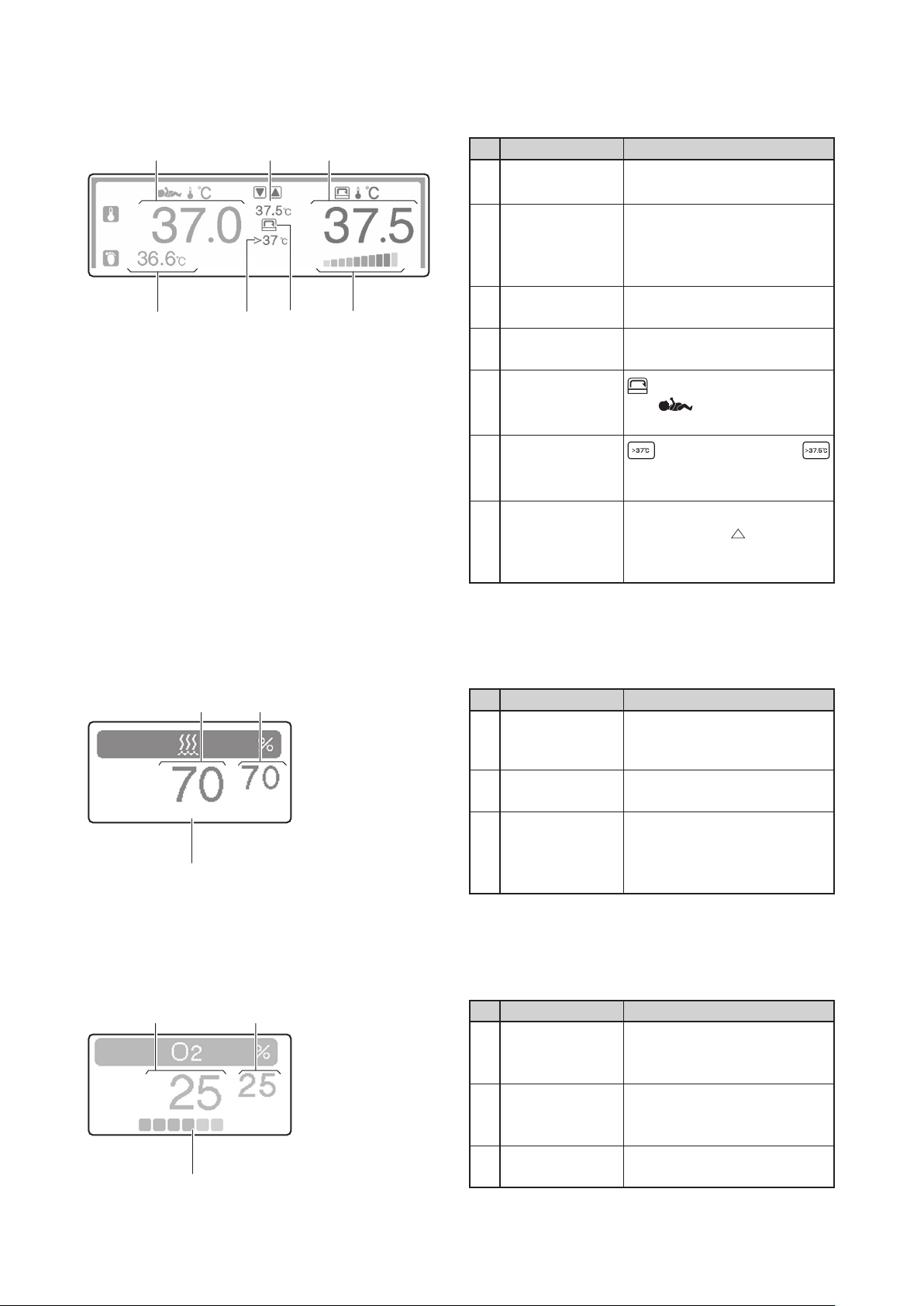
Temperature area (See p.24)
Relative humidity area (See p.24)
Message area (See p.26)
Clock and other indicators area
(See p.26)
Oxygen area (See p.24)
Screen display switch area
(See p.25)
Pulse area (See p.25)
Heat area (See p.26)
Timer area (See p.27)
Message area (See p.26)
Clock and other indicators area
(See p.26)
Pulse area (See p.25)
Screen display switch area
(See p.25)
Main screen2-3-4.
Incubator mode•
Radiant warmer mode•
Page 26
24
Parts Identification
③① ②
④
⑥⑦
⑤
① ②
③
① ②
③
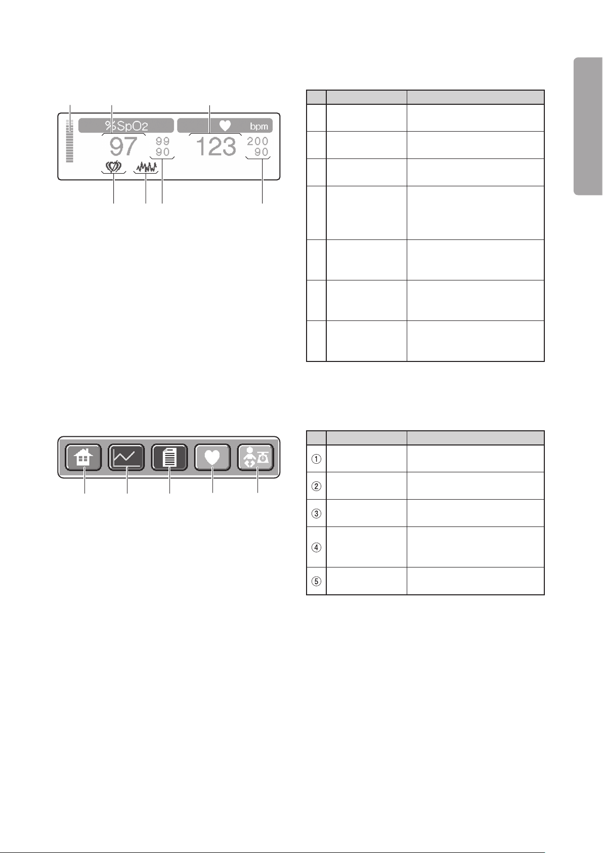
[Temperature area] (Incubator mode)
Touch this area to start the temperature-related setting operation. ✽
No. Name Description
Skin temperature
①
1 display
Displays a detected skin temperature 1 digitally.
Displays a set incubator air tem-
Set temperature
②
display
perature in manual control.
Displays a set skin temperature
1 in servo control.
Incubator air tem-
③
perature display
Heater output
④
indicator
Displays a detected incubator
air temperature digitally.
Indicates the heat supply in 10
levels.
comes on in manual control
Mode indicator
⑤
and comes on in servo
control.
Override indica-
⑥
tor
(in manual control) or
(in servo control) comes on in
the override mode.
Displays a detected skin tem-
Skin temperature
⑦
2 display
perature 2 or
skin temperature 1–detected
T (detected
skin temperature 2) digitally.
[Relative humidity area] (Incubator mode)
Touch this area to start the relative humidity-related setting operation. ✽
[Oxygen area] (Incubator mode)
Touch this area to start the oxygen-related setting operation. ✽
No. Name Description
Relative humid-
①
ity display
Set relative hu-
②
midity display
Displays a detected relative
humidity in the incubator digitally.
Displays a set relative humidity
digitally.
Indicates the level of water in
Water level
③
indicator
the humidity chamber or the
state of the humidity chamber.
No. Name Description
Oxygen concen-
①
tration display
Set oxygen
concentration
②
display
Oxygen flow
③
rate indicator
Displays a detected oxygen
concentration in the incubator
digitally.
Displays a set oxygen concentration digitally.
Indicates a detected oxygen
flow rate in 6 levels.
Page 27
25
PLEASE READ WITHOUT FAIL
Parts Identification
② ③①
④
⑤
⑥⑦
① ② ③
④ ⑤
[Pulse area]
Touch this area to start the pulse oximeter-related setting operation. ✽
No. Name Description
Plethysmograph
①
bar
2 display
%SpO
②
Pulse rate
③
display
Indicates changes in the arterial flow.
Displays a detected SpO2 value
digitally.
Displays a detected pulse rate
digitally.
Displays a pulse rate upper
Pulse rate alarm
④
limits display
alarm limit above and a pulse
rate lower alarm limit below
digitally.
SpO
⑤
limits display
Interference
indicator
⑥
(Nellcor only)
Pulse search
indicator
⑦
(Nellcor only)
2 alarm
Displays an SpO2 upper alarm
limit above and an SpO2 lower
alarm limit below digitally.
Comes on when interference
is detected.
Comes on when no pulse is
detected.
[Screen display switch area]
No. Name Description
Main screen
display switch
Trend screen
display switch
Menu screen
display switch
Pulse oximeter
screen display
switch
Weight screen
display switch
Touch this switch to have the
main screen displayed.
Touch this switch to have the
trend screen displayed.
Touch this switch to have the
menu screen displayed.
Touch this switch to have the
pulse oximeter screen displayed.
Touch this switch to have the
weight screen displayed.
Page 28
26
Parts Identification
②
①
③
④
Message area
① ②
③
⑤ ④
⑥
[Clock and other indicators area]
[Message area]
Messages other than those related to operations are displayed in this area. ✽
No. Name Description
Alarm silence
①
switch
Date display
②
Time display
③
Touch this switch to silence an
active audible alarm temporarily or reset an alarm condition.
Displays a date in the month/
day/year format.
Displays a time in the
hour:minute format.
Comes on only when the in-
Battery indicator
④
ternal batter y (Power Pack
option) is used.
i
:
[Heat area] (Radiant warmer mode)
Touch this area to start the heater output-related setting operation. ✽
No. Name Description
Skin tempera-
①
ture 1 display
Displays a detected skin temperature 1 digitally.
Displays a set heater output in
Set heat display
②
manual control.
Displays a set skin temperature
1 in servo control.
Heater output
③
indicator
Override indica-
④
tor
Indicates the heat supply in 10
levels.
comes on in the override
mode.
comes on in manual con-
Mode indicator
⑤
trol and comes on in
servo control.
Displays a detected skin tem-
Skin tempera-
⑥
ture 2 display
perature 2 or
skin temperature 1 –detected
T (detected
skin temperature 2) digitally.
Page 29

27
PLEASE READ WITHOUT FAIL
Parts Identification
② ③①
④
[Timer area] (Radiant warmer mode)
Touch this area to activate the timer. ✽
No. Name Description
Timer type indi-
①
cator
Timer display
②
Bell indicator
③
Second counter
④
Indicates the timer type currently selected.
Displays how much time
has elapsed digitally in the
minute:second format.
A bell appears when a chime
rings.
Activates ever y 30 seconds
only in the CPR timer mode.
Comes on segment by segment
as each second passes.
Page 30
28
Parts Identification
Incubator numerical
values area (See p.29)
Message area✽
(See p.26)
Clock and other
indicators area (See p.26)
Screen display switch area
(See p.25)
Pulse area (See p.31)
Radiant warmer numerical
values area (See p.30)
Message area✽
(See p.26)
Clock and other
indicators area (See p.26)
Screen display switch area
(See p.25)
Pulse area (See p.31)
Pulse Oximeter Screen2-3-5.
Incubator mode•
The pulse area shown in the figure above is for a Masimo pulse oximeter. ✽
Radiant warmer mode•
The pulse area shown in the figure above is for a Masimo pulse oximeter. ✽
The screen display switch area, the clock and other indicators area, and the message area are the same as ✽
those of the main screen (“2-3-4. Main Screen”). (Therefore there is no reference to them below.)
Page 31

29
PLEASE READ WITHOUT FAIL
Parts Identification
①
④
⑤
⑧
⑨
⑩
②
③
⑦
⑥
Temperature
area
Relative
humidity
area
Oxygen
area
[Incubator numerical values area]
Touch an appropriate area (the temperature area, the relative humidity area, or the oxygen area) to start the ✽
area-related setting operation. (You can follow the same procedure as on the main screen.)
No. Name Description
Incubator air
temperature
①
display
Displays a detected incubator
air temperature digitally.
Displays a set incubator air temperature in manual control (in
the same color as the detected
Set temperature
②
display
incubator air temperature).
Displays a set skin temperature
1 in servo control (in the same
color as the detected skin temperature 1).
Override
③
indicator
Skin tempera-
④
ture 1 display
Comes on in the override
mode.
Displays a detected skin temperature 1 digitally.
Displays a detected skin tem-
Skin tempera-
⑤
ture 2 display
perature 2 or
skin temperature 1 –detected
skin temperature 2) digitally.
Relative humid-
⑥
ity display
Displays a detected relative
humidity in the incubator digitally.
Indicates the level of water in
Water level
⑦
indicator
the humidity chamber or the
state of the humidity chamber.
Set relative hu-
⑧
midity display
Set oxygen
concentration
⑨
display
Oxygen concen-
⑩
tration display
Displays a set relative humidity
digitally.
Displays a set oxygen concentration digitally.
Displays a detected oxygen
concentration in the incubator
digitally.
T (detected
Page 32

30
Parts Identification
④
⑤
⑧
⑥
⑨
②
③
⑦
①
Heat area
Timer area
[Radiant warmer numerical values area]
Touch an appropriate area (the heat area or the timer area) to start the area-related setting operation. ( You ✽
can follow the same procedure as on the main screen.)
No. Name Description
Preheat indica-
①
tor
Comes o n in the p rehe a t
mode.
Displays a set heater output in
manual control (in the same
color as the heater output).
Set heat display
②
Displays a set skin temperature
1 in servo control (in the same
color as the detected skin temperature 1).
Override indica-
③
tor
Skin temperature
④
1 display
comes on in the ser vo
control override mode.
Displays a detected skin temperature 1 digitally.
Displays a detected skin tem-
Skin temperature
⑤
2 display
perature 2 or
skin temperature 1 –detected
T (detected
skin temperature 2) digitally.
Timer type indi-
⑥
cator
Bell indicator
⑦
Indicates the timer type currently selected.
A bell appears when a chime
rings.
Displays how much time
Timer display
⑧
has elapsed digitally in the
minute:second format.
Activates ever y 30 seconds
Second counter
⑨
only in the CPR timer mode.
Comes on segment by segment
as each second passes.
Page 33

31
PLEASE READ WITHOUT FAIL
Parts Identification
③
①
②
④
⑫
⑬
The unit provided with the Masimo
pulse oximeter
The unit provided with the Nellcor
pulse oximeter
⑨
⑪
⑩
⑥
⑦
⑤
⑧
[Pulse area]
The pulse area is the same in the incubator mode and in the radiant warmer mode. ✽
Touch this area to start the pulse oximeter-related setting operation. ✽
No. Name Description
%SpO
①
SpO
②
its display
Pulse rate
③
display
2 display
2 alarm lim-
Displays a detected SpO2 value
digitally.
Displays an SpO2 upper alarm
limit above and an SpO2 lower
alarm limit below digitally.
Displays a detected pulse rate
digitally.
Displays a pulse rate upper
Pulse rate alarm
④
limits display
alarm limit above and a pulse
rate lower alarm limit below
digitally.
PI display Displays the perfusion index.
⑤
Set sensitivity in-
⑥
dicator
FastSat
⑦
indicator
Indicates the currently selected sensitivity (Max, Normal,
APOD).
Comes on when the FastSat
mode is ON
The numerical value on the left
is the SatSeconds setting. The
circular indicator on the right
changes color little by little
clockwise each time a detected
2 is found to be above the
SpO
SpO2 upper alarm limit or be-
SatSeconds display
⑧
(Nellcor only)
low the SpO2 lower alarm limit.
When the whole indicator has
changed color, either the SpO2
upper limit alarm or the SpO2
lower limit alarm will occur
appropriately. The discolored
area will decrease little by little
counterclockwise each time a
detected SpO2 is found to be
within the acceptable range.
Indicates that the response
Fast respons e
mode indicator
⑨
(Nellcor only)
mode is set to “Fast.” This
indicator will disappear when
the response mode is switched
to “Normal.”
Interference
⑩
indicator (Nellcor only)
Pulse search
⑪
indicator (Nellcor only)
Pulse waves
⑫
display
Comes on when interference
is detected.
Comes on when no pulse is
detected.
Displays pulse waves.
Displays the Signal IQ (SIQ)
bar graph.
The height of each bar is in
proportion to the quality of the
SIQ display
⑬
(Masimo only)
input signal concerned. The
more reliable a measured value
is, the higher the bar becomes.
The less reliable a measured
value is, the lower the bar
becomes.
✽1
Page 34

32
Parts Identification
✽1 The higher the SatSeconds limit is set, the longer it takes for the upper or lower limit alarm to occur. Set
the SatSeconds limit appropriately by taking into consideration the patient’s condition. For example, select
a higher setting for monitoring an active patient whose %SpO2 values tend to fluctuate greatly.
The upper or lower limit alarm will occur even when the whole indicator has not changed color if a detected
%SpO2 value deviates from the acceptable range three or more times within 60 seconds.
Page 35

33
PLEASE READ WITHOUT FAIL
Parts Identification
Incubator numerical
values area (See p.34)
Message area✽
(See p.26)
Clock and other
indicators area (See p.26)
Screen display switch area
(See p.25)
Weight area
(See p.35)
Radiant warmer numerical
values area (See p.34)
Message area✽
(See p.26)
Clock and other
indicators area (See p.26)
Screen display switch area
(See p.25)
Weight area
(See p.35)
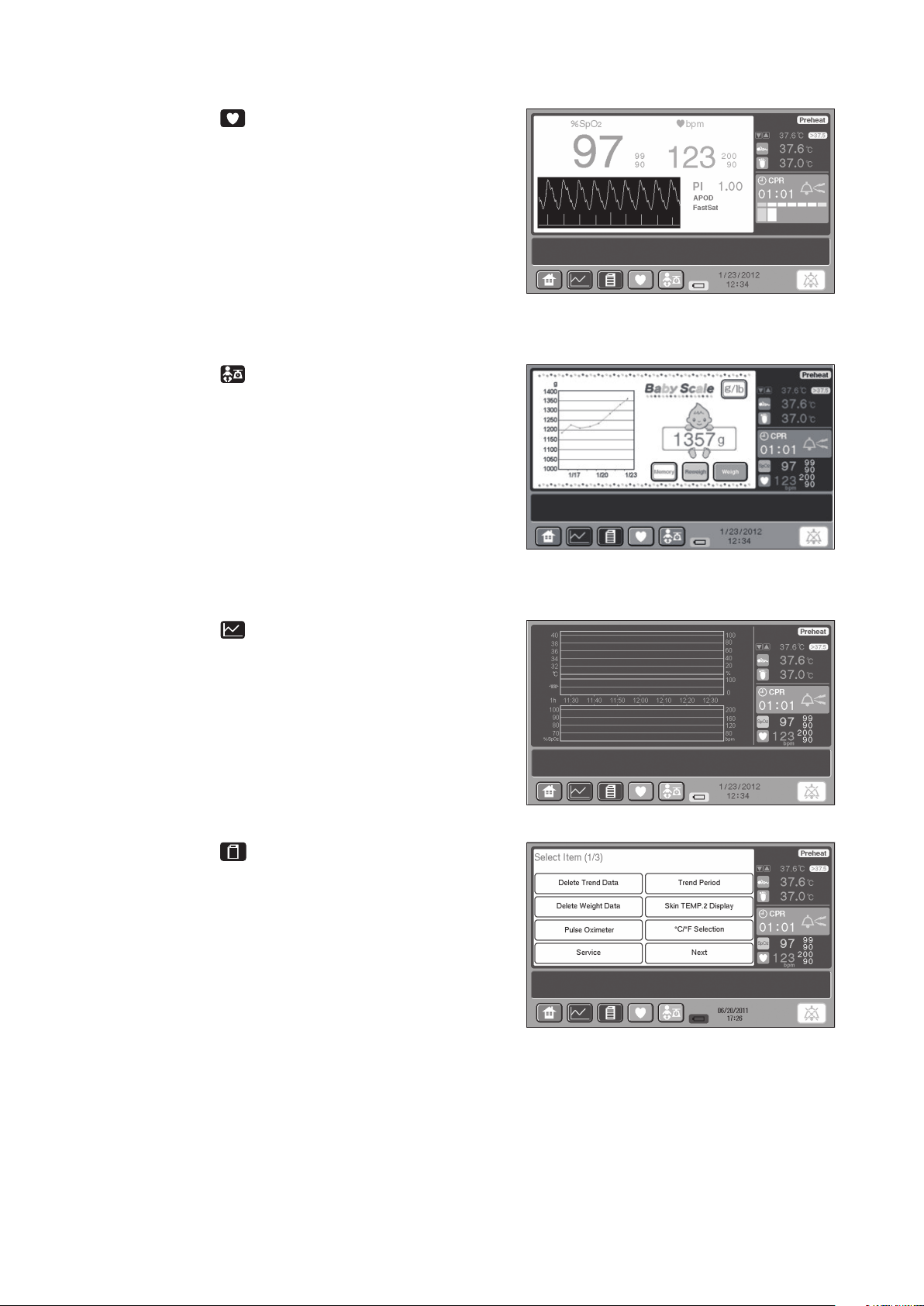
Weight Screen2-3-6.
The weight screen is displayed only when the unit is equipped with the weight monitor unit. ✽
Incubator mode•
Radiant warmer mode•
The screen display switch area, the clock and other indicators area, and the message area are the same as ✽
those of the main screen (“2-3-4. Main Screen”). (Therefore there is no reference to them below.)
Page 36

34
Parts Identification
Temperature
area
Relative
humidity area
Oxygen area
Pulse area
④
③
①
②
⑦
⑥
④
③
①
Heat area
Timer area
Pulse area
⑤
②
[Incubator numerical values area] (Incubator mode)
The temperature area, the relative humidity area, and the oxygen area are the same as those of the pulse ✽
oximeter screen. You can follow the same procedure as on the pulse oximeter screen.
Touch the pulse area to start the pulse-related setting operation. ✽
No. Name Description
2 display
%SpO
①
2 alarm
SpO
②
limits display
Pulse rate alarm
③
limits display
Pulse rate dis-
④
play
Displays a detected SpO2 value
digitally.
Displays an SpO2 upper alarm
limit above and an SpO2 lower
alarm limit below digitally.
Displays a pulse rate upper
alarm limit above and a pulse
rate lower alarm limit below
digitally.
Displays a detected pulse rate
digitally.
[Radiant warmer numerical values area] (Radiant warmer mode)
The heat area is the same as that of the pulse oximeter screen. ✽
The timer area is the same as that of the pulse oximeter screen except that the second counter is exclud- ✽
ed.
The pulse area is the same as that of the incubator numerical values area. ✽
No. Name Description
Timer type indi-
①
cator
Bell indicator
②
Timer display
③
%SpO
④
SpO
⑤
limits display
Pulse rate alarm
⑥
limits display
Pulse rate dis-
⑦
play
2 display
2 alarm
Displays the timer type currently selected.
A bell appears when a chime
rings.
Displays how much time
has elapsed digitally in the
minute:second format.
Displays a detected SpO2 value
digitally.
Displays an SpO2 upper alarm
limit above and an SpO2 lower
alarm limit below digitally.
Displays a pulse rate upper
alarm limit above and a pulse
rate lower alarm limit below
digitally.
Displays a detected pulse rate
digitally.
Page 37

35
PLEASE READ WITHOUT FAIL
Parts Identification
③ ②
①
⑥
④⑤
[Weight area]
The weight area is the same in the incubator mode and in the radiant warmer mode.
No. Name Description
Displays a message related to
weighing when weighing is in
Weight display
①
area
Weigh switch
②
Reweigh switch
③
Memory switch
④
Weight trend
⑤
area
⑥
selector
switch
progress.
Displays a weight reading of
the infant when weighing is not
in progress.
Touch this switch to star t
weighing the infant automatically.
This switch appears only when
a tare weight is established.
Touch this switch to weigh the
infant without performing the
tare deduction process.
Touch this switch to record the
weight reading.
Displays a weight trend
graph.
Touch the trend graph area to
have a list of weight readings
displayed.
Touch this switch to switch
the unit of weight from gram
to pound and ounce, and vice
versa.
Page 38

36
Parts Identification
Incubator numerical
values area (See p.34)
Message area✽
(See p.26)
Clock and other
indicators area (See p.26)
Screen display switch area
(See p.25)
Menu area
(See p.37-39)
Radiant warmer numerical
values area (See p.34)
Message area✽
(See p.26)
Clock and other
indicators area (See p.26)
Screen display switch area
(See p.25)
Menu area
(See p.37-39)
Menu Screen2-3-7.
Incubator mode•
Radiant warmer mode•
The screen display switch area, the clock and other indicators area, and the message area are the same as ✽
those of the main screen (“2-3-4. Main Screen”). (Therefore there is no reference to them below.)
[Numerical values area]
The incubator numerical values area and the radiant warmer numerical values area are the same as those ✽
of the weight screen (“2-3-6. Weight Screen”).
Page 39

37
PLEASE READ WITHOUT FAIL
Parts Identification
[Menu area 1]
The menu area 1 is the same in the incubator mode and in the radiant warmer mode. ✽
This screen appears first when the menu screen is selected. ✽
No. Name Description
Delete Trend
①
Data switch
Delete Weight
②
Data switch
Pulse Oximeter
③
switch
Service Menu
④
switch
Trend Period
⑤
selector switch
Skin TEMP. 2
⑥
Display switch
°C/°F selector
⑦
switch
Next switch
⑧
Touch this switch to delete the
trend data displayed on the
trend screen.
Touch this switch to delete the
weight data displayed on the
weight screen.
Touch this switch to have the
menu area 3 displayed for the
pulse oximeter-related setting
operation.
This switch is used for advanced settings of the unit. For
details of the operation of this
switch, see “2-4. Service Menu
(How to Operate the Service
Menu Screen).”
Touch this switch to select a
trend period to be displayed on
the trend screen.
Touch this switch to have
either a detected skin temperature 2 or
temperature 1 – detected skin
temperature 2) displayed in the
temperature area.
Touch this switch to switch the
unit of temperature from °C to
°F, and vice versa.
Touch this switch to have the
menu area 2 displayed.
T (detected skin
Page 40

38
Parts Identification
[Menu area 2]
The menu area 2 is the same in the incubator mode and in the radiant warmer mode. ✽
Select [Next] in the menu area 1 to enter this screen. ✽
No. Name Description
LCD Screen
Brightness se-
①
lector switch
Light Sensor
Level selector
②
switch
Timer selector
③
switch
Go Back switch
④
Alarm Volume
⑤
selector switch
Clock setting
⑥
switch
Next switch
Touch this switch to set the
brightness of the display screen
to a desired level.
Touch this switch to set the
light sensor level to a desired
level in switching to the night
mode.
Touch this switch to select and
set the timer type in the radiant
warmer mode.
Touch this switch to return to
the menu area 1.
Touch this switch to set an
alarm volume to a desired
level.
Touch this switch to set the
year, the month, the date, the
hour and the minute.
Touch this switch to have the
menu area 3 displayed.
[Menu area 3]
The menu area 3 is the same in the incubator mode and in the radiant warmer mode. ✽
Select [Next] in the menu area 2 to enter this screen. ✽
No. Name Description
Touch this switch to check
Filter used time
RESET switch
the number of hours the filter
has been used and reset the
elapsed time.
O2 Sensor days
of use RESET
switch
Go Back switch
Touch this switch to check the
number of days the oxygen sensors have been used and reset
the elapsed days.
Touch this switch to return to the
menu area 2.
Page 41

39
PLEASE READ WITHOUT FAIL
Parts Identification
①
②
③
④⑤
[Menu area 4]
The menu area 4 is the same in the incubator mode and in the radiant warmer mode. ✽
Select [Pulse Oximeter] in the menu area 1 to enter this screen. ✽
<The unit equipped with the Masimo pulse oximeter>
No. Name Description
Synchronizing
Pulse Beep
①
volume selector
switch
Sensitivity se-
②
lector switch
Go Back switch
③
Averaging Time
④
selector switch
FastSat selector
⑤
switch
Touch this switch to set the volume of the synchronizing pulse
beep of the pulse oximeter to a
desired level.
Touch this switch to set the
sensitivity of the pulse oximeter
to a desired level.
Touch this switch to return to
the menu area 1.
Touch this switch to set the
averaging time of the pulse
oximeter.
Touch this switch to enable or
disable the FastSat mode of the
pulse oximeter.
<The unit equipped with the Nellcor pulse oximeter>
No. Name Description
Synchronizing
Pulse Beep
volume selector
switch
SatSeconds
selector switch
Go Back switch
Response Mode
selector switch
Touch this switch to set the volume of the synchronizing pulse
beep of the pulse oximeter to a
desired level.
Touch this switch to set SatSeconds as desired.
Touch this switch to return to
the menu area 1.
Touch this switch to set the
response mode as desired.
Page 42

40
Parts Identification
Incubator numerical
values area (See p.34)
Message area✽
(See p.26)
Tr end area
(See p.41)
Clock and other
indicators area (See p.26)
Screen display switch area
(See p.25)
Radiant warmer numerical
values area (See p.34)
Message area✽
(See p.26)
Tr end area
(See p.41)
Clock and other
indicators area (See p.26)
Screen display switch area
(See p.25)
Trend Screen2-3-8.
Incubator mode•
Radiant warmer mode•
The screen display switch area, the clock and other indicators area, and the message area are the same as ✽
those of the main screen (“2-3-4. Main Screen”). (Therefore there is no reference to them below.)
[Numerical values area]
The incubator numerical values area and the radiant warmer numerical values area are the same as those ✽
of the weight screen (“2-3-6. Weight Screen”).
Page 43

41
PLEASE READ WITHOUT FAIL
Parts Identification
Ⓐ
Ⓑ
C
[Trend area]
No. Name Description
A temperature scale (the incubator air temperature, the skin
temperature 1 and the skin
temperature 2) is provided on
Trend 1
Trend 2
Trend 3
the left axis and a % scale (the
relative humidity and the oxygen concentration) is provided
on the right axis to display a
trend graph of each item.
Displays a trend graph of
changes in the heater output
(the main heater and the radiant warmer heater).
A %SpO2 scale is provided on
the left axis and a pulse rate
scale (bpm) is provided on the
right axis to display a trend
graph of each item.
Page 44

42
Parts Identification
Service Menu (How to Operate the Service Menu Screen)2-4.
(The service menu is not accessible to ordinary users.)
How to Enter the Service Menu2-4-1.
(1) Touch on any other screen, and the menu screen
will appear.
Touch “Service Menu” on the menu screen.(2)
(3) When the password entry screen is displayed, touch
the numeric keys in the following order: “3” → “6”
→ “6” → “1”.
(4) The Service Menu screen (1/2) is displayed. Touch
[Next], and the Service Menu screen (2/2) will appear. To return to the screen (1/2), touch [Go back].
To return to the password entry screen, touch [Go
back] on the Service Menu screen (1/2). To return
to the menu screen, touch [Go back] on the password entry screen.
Page 45

43
PLEASE READ WITHOUT FAIL
Parts Identification
Operating the Service Menu Screen2-4-2.
Setting the Key Click Sound2-4-2-1.
(1) Touch [Key Click Sound] on the Ser vice Menu
screen (1/2).
When the key click sound has been disabled be-(2)
forehand, a message to confirm whether to enable
the key click sound will appear. Touch
the key click sound will be enabled. To cancel this
procedure, touch [CLOSE]. The key click sound will
remain disabled.
When the key click sound has been enabled be-(3)
forehand, a message to confirm whether to disable
the key click sound will appear. Touch
the key click sound will be disabled. To cancel this
procedure, touch [CLOSE]. The key click sound will
remain enabled.
, and
, and
Setting the Language2-4-2-2.
(1) Touch [Languages] on the Service Menu screen
(1/2). A list of the languages available for use on
the display will appear. Touch the language you
want to use.
Page 46

44
Parts Identification
CAUTION
Setting the Baby Check Alarm2-4-2-3.
You are not allowed to disable the baby check
alarm (IEC 60601-2-21). If you need to disable
the baby check alarm, contact your local Atom
representative.
(1) Touch [Baby Check] on the Service Menu screen
(1/2).
When the baby check alarm has been enabled be-(2)
forehand, a message to confirm whether to disable
the baby check alarm will appear. Touch
the baby check alarm will be disabled. To cancel this
procedure, touch [CLOSE]. The baby check alarm
will remain enabled.
, and
When the baby check alarm has been disabled be-(3)
forehand, a message to confirm whether to enable
the baby check alarm will appear. Touch
the baby check alarm will be enabled. To cancel this
procedure, touch [CLOSE]. The baby check alarm
will remain disabled.
Setting the MC Alarm Threshold 2-4-2-4.
(1) Touch [MC Alarm Threshold] on the Service Menu
screen (1/2).
When the threshold has been set to ±3.0(2) ℃ before-
hand, a message to confirm whether to change it to
±1.5℃ will appear. Touch
will be changed to ±1.5℃. To cancel this procedure,
touch [CLOSE]. The threshold will remain ±3.0℃.
When the threshold has been set to ±1.5(3) ℃ before-
hand, a message to confirm whether to change it to
±3.0℃ will appear. Touch
will be changed to ±3.0℃. To cancel this procedure,
touch [CLOSE]. The threshold will remain ±1.5℃.
, and the threshold
, and the threshold
, and
Page 47

45
PLEASE READ WITHOUT FAIL
Parts Identification
Setting the SC Alarm Threshold2-4-2-5.
(1) Touch [SC Alarm Threshold] on the Service Menu
screen (1/2)
When the threshold has been set to ±1.0(2) ℃ before-
hand, a message to confirm whether to change it to
±0.5℃ will appear. Touch
, and the threshold
will be changed to ±0.5℃. To cancel this procedure,
touch [CLOSE]. The threshold will remain ±1.0℃.
When the threshold has been set to ±0.5(3) ℃ before-
hand, a message to confirm whether to change it to
±1.0℃ will appear. Touch
, and the threshold
will be changed to ±1.0℃. To cancel this procedure,
touch [CLOSE]. The threshold will remain ±0.5℃.
Checking How Many Hours the Filter Has Been Used2-4-2-6.
(1) Touch [Filter used time (h) RESET] on the Service
Menu screen (2/2).
The number of hours for which the filter has been (2)
used so far and a message to confirm whether to
reset the counter will appear. To finish the procedure
without resetting the counter, touch [CLOSE]. To
reset the counter, touch
.
Checking How Many Days the Oxygen Sensors Have Been Used2-4-2-7.
(1) Touch [O
2 sensor days of use RESET] on the Service
Menu screen (2/2).
The number of days for which the oxygen sensors (2)
have been used so far and a message to confirm
whether to reset the counter will appear. To finish
the procedure without resetting the counter, touch
[CLOSE]. To reset the counter, touch
.
Page 48

46
Parts Identification
Alarm History2-4-2-8.
(1) Touch [Alar m Histor y] on the Ser vice Menu
screen.
The time(s) when the power was turned on, the (2)
time(s) when the power was turned off, and the
time(s) when an alarm or alarms occurred will be
displayed.
Touch (3) [CLOSE] to finish viewing the alarm his-
tory.
Adjusting the Weight Monitor with a 5 kg Weight2-4-2-9.
Obtain a 5 kg weight in advance. ✽
Be sure to change the unit of weighing to be displayed on the screen to “g” before starting the 5kg adjust- ✽
ment.
(1) Touch [Weighing Scale 5 kg Adjustment] on the
Service Menu screen (2/2).
A message to confirm whether to begin adjustment (2)
of the weighing scale will appear. Touch
. After
the message has disappeared, touch the weight
screen display switch to have the weight screen
displayed. If you touch [CLOSE] instead of
, the
adjustment procedure will not be started even when
the weight screen is displayed.
When the weight screen appears, 0kg adjustment (3)
will be started. Do not place anything on the bed.
Wait for 5 ~ 10 seconds until the weight reading
stabilizes.
(4) After the weight reading has stabilized, touch
and a message “With the Weight Placed, Touch the
Reweigh switch” will appear. Place a 5 kg standard
weight gently on the center of the bed and wait for 5
~10 seconds until the weight reading stabilizes.
,
Page 49

47
PLEASE READ WITHOUT FAIL
Parts Identification
Reweigh
(5) After the weight reading has stabilized, touch
and the 5kg adjustment will be completed.
(6) If a message “Repeat the adjustment” should appear,
return to the 0kg adjustment.
With nothing placed on the bed, wait for 5 ~ 10 seconds until the weight reading stabilizes. Touch ,
and the message “With the Weight Placed, Touch the
Reweigh switch” will appear. Place the 5 kg standard
weight gently on the center of the bed and wait for
5 ~10 seconds. Then repeat (5) to complete the 5kg
adjustment successfully.
,
Setting History2-4-2-10.
(1) Touch [Setting History] on the Service Menu screen
(2/2).
A list of the date and time when the settings were (2)
done and the details of the settings will be displayed.
Touch (3) [CLOSE] to finish viewing the alarm his-
tory.
Calibrating the Touch Panel2-4-3.
(1) Turn the power on and the start screen will appear.
Touch this screen three times.
Page 50

48
Parts Identification
(2) A message “Touch Screen Calibration. Point to the
dot” will appear. Touch the dot displayed on the upper left corner of the screen.
(3) Then a dot will be displayed on the lower right corner
of the screen. Touch the dot. The touch panel will
have been calibrated successfully if the main screen
is displayed.
Page 51

49
MAINTENANCE
Maintenance Inspection
CAUTION
Maintenance Inspection[3]
The description in this section relates to a unit which is equipped with a weight monitor. Please skip any ✽
reference unrelated to your unit.
Medical institutions are responsible for performing the maintenance inspections.
They are allowed to entrust the maintenance inspections of the unit to an appropriate external
contractor.
Clean and disinfect the unit and its accessories before maintenance inspections, repairs, or dis-
posal.
Maintenance service should be performed properly by a qualified person in accordance with this
Service Manual.
Precautions in performing maintenance inspections
1. When you choose to have the unit maintained and inspected or when the unit is found to be in need of
repairs from the results of inspection, consult your local Atom representative and take one of the following
measures.
1) Ask someone who has completed a training course specified by Atom and who has sufficient technical
knowledge and skills to do the work.
2) Ask Atom to send its service engineer if a person who has completed a training course specified by Atom
and who has sufficient technical knowledge and skills is not available.
3) Ask Atom for its approval of returning the unit for repair service.
2. Read the operating precautions thoroughly before operating the unit.
3. Periodical inspection is needed to use the unit in the optimum condition.
4. Ensure that the unit will not be used if it is found to be defective.
Take proper measures to ensure that a defective unit will not be used by mistake before it is properly in-
spected, repaired and has its settings changed for normal operation. Such measures include indicating on
the unit that it is under inspection/repair and keeping it away from other devices that function correctly.
In order to use the unit safely for a longer period, perform the maintenance inspections described below.
Inspection before use•
Check the basic functional operation of each part of the unit every time you are going to use the unit.
Quarterly inspection•
Check the operation of each function of the unit every three months.
However, the unit should be inspected at shorter intervals if it is used frequently.
Parts requiring periodical replacement•
Some parts need to be replaced periodically depending on their period of use.
Page 52

50
Maintenance Inspection
CAUTION
Inspection before Use3-1.
Check the following points every time you are going to use the unit.
If you should notice any strange smell, strange noise, overheating or strange vibration when the
power is applied to the main body in the inspection before use, stop using the unit immediately and
contact your local Atom representative.
Visual Inspection3-1-1.
Item to check Description
Appearance
Snap-open access port
packing
Canopy packing
X-ray cassette tray door
packing
Patient circuit slot grommet
Tube introduction slit packing
Sensor module
Admittance panel operating
knob
Admittance panel operating
lever
Baby guard
Snap-open access port
Tilting unit
Power switch
Incubator mode switch,
Radiant warmer mode switch
The main body and the hood should be neither broken nor deformed. (Otherwise, the infant and/or the user may get injured due to breakage, etc.)
Each packing should be attached correctly to the access port. It should be
intact. (Otherwise, the air tight seal may be compromised.)
Each packing should be attached correctly to the hood. It should be intact.
(Otherwise, the air tight seal may be compromised.)
The packing should be attached correctly to the X-ray cassette tray door. It
should be intact. (Otherwise, the air tight seal may be compromised.)
It should be attached correctly to the hood. It should be intact. (Otherwise,
the air tight seal may be compromised.)
Each packing should be attached correctly to the hood. It should be intact.
(Otherwise, the air tight seal may be compromised.)
It should be neither broken nor deformed. (Otherwise, unsatisfactory control
may result from faulty detection by the sensors.)
Each knob should be held in place securely and should open and close the
admittance panel reliably. (Other wise, the infant may fall out of the baby
compartment due to incomplete locking.)
With an admittance panel closed, hold the admittance panel operating knobs
and pull the admittance panel toward you. It should not open. (Otherwise, the
infant may fall out of the baby compartment due to incomplete locking.)
It should be neither broken nor deformed. (Otherwise, the infant may fall
out of the baby compartment due to incomplete attachment.)
Each access port should be held in place securely and should open and close
reliably. With the snap-open access port closed, the red line should not be
visible at the locking part. (Other wise, the infant may fall out of the baby
compartment due to incomplete locking.)
The mattress platform should tilt smoothly when the tilting knob is operated.
(Otherwise, the mattress platform may not tilt.)
It should turn the power on and off reliably. (Otherwise, it may not function.)
The incubator should enter the incubator mode when the incubator mode
switch is pressed.
The incubator should enter the radiant warmer mode when the radiant
warmer mode switch is pressed.
Page 53

51
MAINTENANCE
Maintenance Inspection
Item to check Description
It should be fixed securely with the fixing device.
Display
Caster
Filter
Skin temperature probe
Skin temperature probe
connecting port
AC inlet The AC inlet should be clean without any adherent medical fluid.
Power cord
Height adjustment mechanism It should operate smoothly without making any strange noise.
Activation of alarms
Operation Manual
(Otherwise, the display may become unstable or fall when a switch is operated.)
Each caster should rotate smoothly. The caster lock should function reliably.
(Otherwise, the unit cannot be relocated easily.)
It should be clean. (Otherwise, air circulation may not be controlled properly.)
An appropriate temperature should be displayed when the skin temperature
probe is connected and the tip of the probe is held in your hand.
The area around the connecting port should be neither broken nor unclean.
The plug should not be deformed.
The cord should not be damaged.
Before connecting the power cord, check the following:
When the power switch is turned on, the power failure alarm indicator should
flash and an audible alarm should sound.
After connecting the power cord, check the following:
When the power switch is turned on, the alarm lamp should come on and
an audible alarm should sound.
It should be kept where it is readily accessible. (Otherwise, the unit may be
operated incorrectly due to lack of accessible information.)
Dead pixels (points on the screen that are always dark) may be found on the LCD display during the inspection. ✽
This is a phenomenon peculiar to an LCD display and not a malfunction. However, if an important message
or a numerical value is not visible due to too many dead pixels, contact your local Atom representative.
Page 54

52
Maintenance Inspection
Tube introduction slit packing
Skin temperature probe
Skin temperature probe
connecting port 1
Humidity chamber cover
Power switch
Functional Inspection3-1-2.
Inspecting the basic functions of the incubator•
(Preparation 1)
(1) Connect the yellow skin temperature probe to the
skin temperature probe connecting por t 1 on the
rear of the main body.
(2) Open the humidity chamber cover down to the posi-
tion shown in the figure on the right. Draw out the
humidity chamber until it stops halfway. Lift up the
humidity chamber slightly and take it out.
Allow the humidity chamber and the water in it to
cool down sufficiently before removing the humidity chamber. Otherwise, you may get scalded. Hold
the humidity chamber with both hands because the
humidity chamber filled with water is heavy.
(Checking the displays and the audible alarm)
(3) Turn on the power switch to activate the system.
Check:
① Does the alarm lamp come on and does the au-
dible alarm sound immediately after the power
switch is turned on?
② Is a numerical value displayed on the incubator
air temperature display?
③ Is a numerical value displayed on the skin tem-
perature 1 display?
④ Is a numerical value displayed on the relative
humidity display?
⑤ Is the “humidity chamber off alarm” indicator
is on?
⑥ Are the alarm indicators other than the “humidity
chamber off alarm” indicator off?
Digital indication includes “LOW/HIGH” indica- ✽
tion.
Page 55
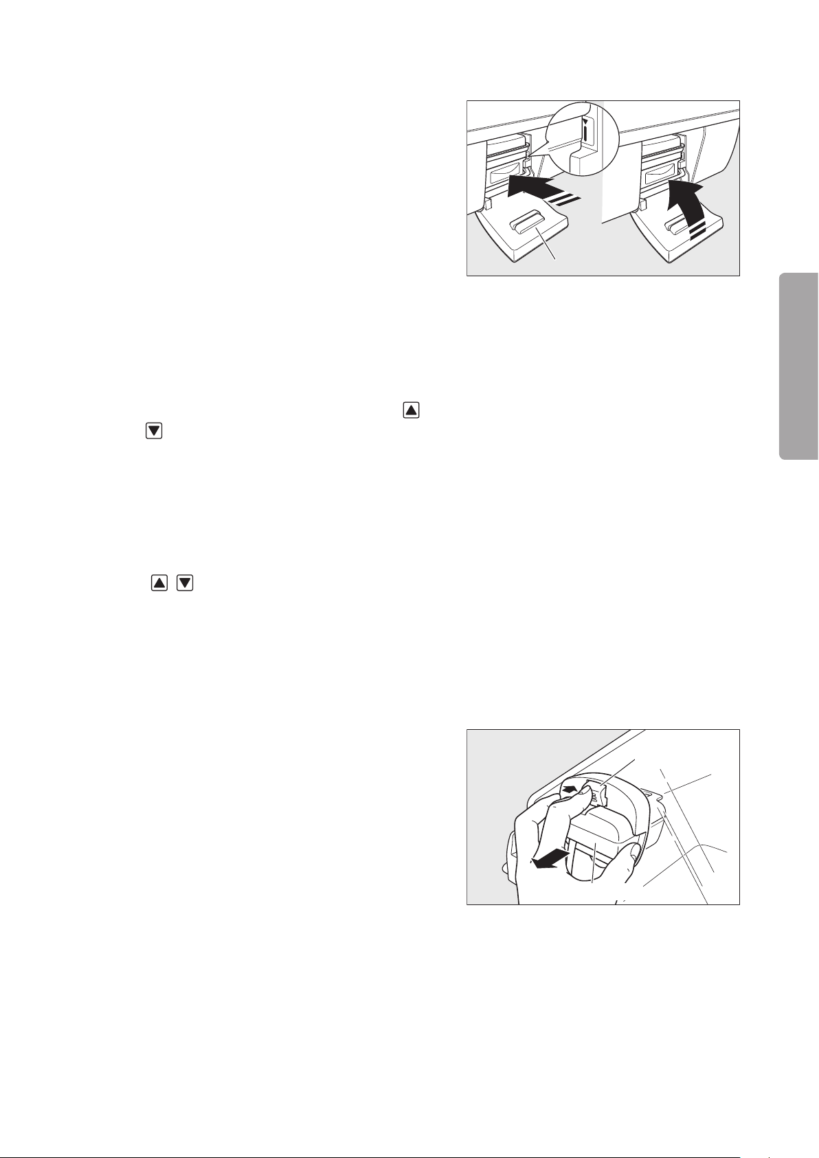
53
MAINTENANCE
Maintenance Inspection
(Checking the humidity chamber)
Humidity chamber cover
Sensor module
Lever
(4) Push the humidity chamber in which the cartridge
tank is placed gently into the main body until the
marking shown in the figure on the right is visible
and close the humidity chamber cover.
Check:
① Does the “humidity chamber off alarm” indicator
go out?
(Checking the temperature setting operation)
Set the temperature to 23.0°C in the manual control (5)
mode.
Check:
① Does the numerical value on the set temperature
display change when either setting switch (
) is touched?
(Checking the relative humidity setting operation)
Set the relative humidity to 95%Rh.(6)
Check:
① Does the numerical value on the set relative hu-
midity display change when either setting switch
(
• ) is touched?
(Checking the oxygen controller)
Enable the oxygen controller function.(7)
Check:
① Is a numerical value displayed on the oxygen
concentration display?
•
(8) While pressing the lever, pull out the sensor module
without removing it from the hood, and perform the
calibration procedure.
Check:
① Is “21%” displayed on the oxygen concentration
display after a while?
Page 56

54
Maintenance Inspection
Tube introduction slit packing
Skin temperature probe
Skin temperature probe
connecting port 1
(Checking the skin temperature probe alarm)
Set the temperature to 37.5°C in the ser vo control (9)
mode.
(10) Remove the skin temperature probe connected to
the skin temperature probe connecting port 1 on
the rear of the main body.
Check:
① Does the skin temperature probe alarm occur?
(Checking the system failure alarm)
Remove the sensor module connector connected to (11)
the rear of the main body.
Check:
① Does the system failure alarm occur?
(Checking the power failure alarm)
Remove the power cord.(12)
Check:
① Does the power failure alarm indicator flash?
② Does the audible alarm sound?
(Preparation 2)
Turn off the power switch.(13)
Attach the power cord.(14)
(Weight monitor)
Connect the weight monitor cable to the connec-(15)
tor for the weight monitor on the rear of the main
body.
Turn on the power switch to activate the system.(16)
Have the weight screen displayed.(17)
Check:
① Is “_ _ _ _ g” displayed on the weight display
area?
Touch (18)
Touch (19)
mattress” is displayed.
Check:
① Does the tare deduction process start and does
② Does the weight reading change when you push
.
again while a message “Lift up baby from
the unit enter the ordinar y weight monitor
mode?
down the mattress platform lightly in the ordinary
weight monitor mode?
Page 57

55
MAINTENANCE
Maintenance Inspection
(Inspection completed)
CAUTION
Turn off the power switch.(20)
If any function is found to be unsatisfactory, refer
to the “Troubleshooting” section and perform the
entire functional inspection once again.
Performance Inspection3-1-3.
Equipment required:
An oxygen flowmeter and an oxygen monitor are required to check the oxygen supply.
(Preparation)
Connect the skin temperature probe to the skin (1)
temperature probe connecting port 1 on the rear of
the main body and place it 10cm above the center
of the mattress surface.
Supply water in the humidity chamber and position (2)
it in the main body.
Turn on the power switch to activate the system.(3)
Set the humidity setting to OFF.(4)
Set the oxygen control to OFF.(5)
(Skin temperature control)
Set the temperature to 36.0°C in the ser vo control (6)
mode.
(Incubator air temperature control)
(Oxygen control)
Check:
① Does the reading on the skin temperature display
stabilize at 36.0±0.5°C?
Set the temperature to 36.0°C in the manual control (7)
mode.
Check:
① Does the reading on the incubator air temperature
display stabilize at 36.0±1°C?
Perform the calibration procedure.(8)
Set the oxygen control to ON.(9)
Supply oxygen through the oxygen supply port 2.(10)
Page 58

56
Maintenance Inspection
CAUTION
Set the oxygen concentration to 40% O(11) 2.
Check:
① Does the reading on the oxygen concentration
display stabilize at 40±2% O
When checking is completed, set the oxygen ✽
control to OFF.
(Oxygen supply)
Supply oxygen through the oxygen supply port 1 at (12)
10L/min using an oxygen flowmeter.
Check:
① Measure the oxygen concentration with an oxy-
gen monitor. Is the reading at least 65% O
Stop the oxygen supply when checking is com- ✽
pleted.
2?
2?
(Humidity control)
Set the relative humidity to 90%Rh.(13)
Check:
① Is the reading on the relative humidity display
90±3%Rh?
(Inspection completed)
Turn off the power switch.(14)
If any performance is found to be unsatisfactory,
refer to the “Troubleshooting” section, and perform
the entire performance inspection once again.
Checking and Calibrating the Weight Monitor3-1-4.
Check and calibrate the weight monitor periodically once a year.
For the calibration procedure, see “2-4-2-9. Adjusting the Weight Monitor with a 5kg Weight.”
Page 59

57
MAINTENANCE
Maintenance Inspection
Quarterly Inspection3-2.
Check the following points every three months.
Item to check Procedure Description
Incubator air tem-
perature control
Skin temperature
control
Humidity control
Oxygen concentra-
tion control
Pulse oximeter
Fan Check the exterior by visual inspection.
Humidifier
Power failure alarm
Weight monitor
(The unit equipped
with the weight
monitor unit)
Set the temperature to 36.0°C in manual
control.
Place the skin temperature probe at about
10cm above the center of the mattress
surface in the incubator and set the temperature to 36.0°C in servo control.
Set RH to 90%Rh with the incubator air
temperature set to 32.0°C.
①When the oxygen controller is not used:
Supply oxygen at 10L/min from the
oxygen supply port 1.
②When the oxygen controller is used:
Connect oxygen to the oxygen supply
port 2 and, after 21%O
the oxygen concentration to 40%O2.
Connect a sensor to the main body and
attach the sensor to the inspector.
①Install the car tridge tank without any
water in it.
②Open the humidity chamber cover.
③Install the humidity chamber with the
boiler cap off.
Turn the power on, and then remove the
power plug from the power outlet.
Place a 5kg weight on the center of the
mattress and check the display.
2 calibration, set
The displayed incubator air temperature
should be stable at 36.0±1°C.
The displayed skin temperature should be
stable at 36.0±0.5°C.
The displayed RH should be stable at
90±3%Rh.
①The oxygen concentration in the incuba-
tor should rise to 65%O2 or higher.
②21%O2 calibration should be completed
successfully, and the displayed oxygen concentration should be stable at
40±2%O2.
95~100% should be displayed on the %SpO
display. The pulse rate should also be
displayed.
It should be neither broken nor deformed.
①The “no water alarm” indicator should
come on.
②The “humidity chamber off alarm” indi-
cator should come on.
③The “humidity chamber off alarm” indi-
cator should come on.
The power failure alarm indicator should
come on and an audible alarm should
sound.
The displayed value should be in the range
of 5000±5g.
2
Page 60

58
Maintenance Inspection
WARNING
Inspection Checklist3-3.
If any trouble is detected in any inspection, indicate on the unit that it is out of order and seek repair
without fail.
Contact your local Atom representative for further information on repairs.
Serial No. ( ) Date of Inspection ( . . ) Inspector ( )
No. Item to check Judgment
Inspection before use (every time)
1 Are the main body and the hood free of breakage and deformation? YES / NO
2 Are the access port packings free of breakage and attached securely to the access ports? YES / NO
3 Are the canopy packings free of breakage and attached securely to the hood? YES / NO
4
Is the X-ray cassette tray door packing free of breakage and attached securely to the X-ray cassette tray door?
5 Is the patient circuit slot grommet free of breakage and attached securely to the hood? YES / NO
6 Are the tube introduction slit packings free of breakage and attached securely to the hood? YES / NO
7 Is the sensor module free of breakage and deformation and fixed securely to the hood? YES / NO
8 Are the admittance panel operating knobs held in place securely and do they operate reliably? YES / NO
9 Are the admittance panels locked securely? YES / NO
10 Are the baby guards free of breakage and deformation? YES / NO
11 Are the access ports held in place securely and do they open and close reliably? YES / NO
12 Does the tilting unit operate smoothly? YES / NO
13 Does the power switch turn the power on and off reliably? YES / NO
Does the incubator enter the incubator mode when the incubator mode switch is pressed?
14
Does the incubator enter the radiant warmer mode when the radiant warmer mode switch is
pressed?
15 Is the fixing device of the display free of breakage and is the display fixed securely? YES / NO
16 Does each caster rotate smoothly and do the caster locks function reliably? YES / NO
17 Is the filter clean without any blackish dirt? YES / NO
Is the correct skin temperature displayed when you hold the tip of the skin temperature probe
18
in your hand?
19 Is the area around the skin temperature connecting port free of breakage and dir t? YES / NO
20 Is the AC inlet clean without any adherent medical fluid? YES / NO
21 Is the plug of the power cord free of deformation and is the power cord free of damage? YES / NO
22 Does the height adjustment mechanism operate smoothly without making any strange noise? YES / NO
23 Does the power failure alarm function properly and does the alarm lamp come on properly? YES / NO
24 Is the Operation Manual readily accessible? YES / NO
Quarterly inspection
1 Is the displayed incubator air temperature stable at 36.0±1°C in manual control? YES / NO
2 Is the displayed skin temperature stable at 36.0±0.5°C in ser vo control? YES / NO
3 Is the displayed RH stable at 90±3%Rh? YES / NO
4 Does the oxygen concentration rise to 65%O
5
Is the displayed oxygen concentration stable at 40±2%O2 when the oxygen control function is on?
6 Is an SpO
7 Is the fan free of breakage? YES / NO
8 Do the “no water alarm” indicator and the “humidity chamber of f alarm” indicator come on? YES / NO
Does an audible alarm sound and does the power failure alarm indicator flash when the power
9
plug is removed from the power outlet?
10 Does the weight display show a correct numerical value when a 5kg weight is weighed? YES / NO
2 value displayed when an SpO2 sensor is connected? YES / NO
2 or higher at 10L/min? YES / NO
YES / NO
YES / NO
YES / NO
YES / NO
YES / NO
Page 61

59
MAINTENANCE
Maintenance Inspection
Periodical Replacement Parts and How to Replace them3-4.
Periodical replacement parts are those which gradually deteriorate and wear down with use. They need periodical replacement to keep the accuracy and performance of the unit at a proper level. Timing of replacement
varies with the frequency and conditions of use. Consult your local Atom representative for replacement.
Part name Period of use Reason for replacement
Filter 3 months
Tube introduction slit
packing
Admittance panel packing 1~2 years
Canopy packing 1~2 years
1~2 years
Dirtiness due to dust or defective air circulation control
due to clogging
Decreased air tightness due to breakage or deformation
Decreased air tightness due to breakage or deformation
Decreased air tightness due to breakage or deformation
Patient circuit slot
grommet
Sn a p -open access por t
packing
X-ray cassette tray door
packing
Mattress 1~2 years Decreased elasticity due to breakage or deformation
Rotary damper
(for an admittance panel)
Fan motor
Fan
Snap-open access port
Humidity chamber
Battery for power failure
alarm
1~2 years
1~2 years
1~2 years
2 years
3 years
3 years
3 years
3 years
4 years
Decreased air tightness due to breakage or deformation
Decreased air tightness due to breakage or deformation
Decreased air tightness due to breakage or deformation
Reduced damper function
Decreased air circulation
Decreased air circulation
Incomplete locking
Insufficient humidification due to breakage or deformation
Defective power failure alarm function due to battery
life
Battery for the display
Variable depending
Oxygen sensor
The oxygen sensor is a consumable item and its life is affected greatly by the ambient conditions under ✽
which it is used (i.e. ambient temperature, oxygen concentration). It is recommended to replace an oxygen
sensor when more than one year has passed since it was taken out of its package.
on operating conditions
4 years
✽
Defective clock control due to battery life
Defective calibration or defective oxygen control due to
sensor life
Page 62

60
Maintenance Inspection
CAUTION
Fresh air intank
Filter cover
CAUTION
Filter
WARNING
Location for
affixing the filter
replacement
record card
Filter cover
Replacing the Filter3-4-1.
Replace the old filter with a new one every three months in general. The dirtiness of the filter var-
ies with the degree of air pollution and the frequency of operation. Check the dirtiness of the filter
through the window of the filter cover. If the filter should be found discolored, replace it with a new
one even if the three-month interval is not over yet.
(1) Loosen the screw of the filter cover and open the
cover.
(2) Detach the filter slowly. Take out the dirty filter,
taking care not to let the dirt fly about.
Do not block the fresh air intake with a wall or a
cloth, etc.
Discard the dirty filter. Clean the filter cover and (3)
the filter holder with a soft cloth dampened with a
disinfectant solution and wrung out suf ficiently.
(4) Attach a new filter to the filter holder. Ensure that the
filter is installed correctly. Enter the date of replacement in the accompanying filter replacement record
card and affix it in place as shown in the figure on
the right for future reference.
Tighten the screw of the filter cover and close the (5)
cover.
Do not attempt to reuse the dirty filter by washing
it or attaching it inside out.
Open the filter cover only to replace the old filter
with a new one.
The unit counts the number of hours of operation after the filter is replaced. When the time comes to replace ✽
the filter, a message appears on the screen to remind the user. The counter must be reset after the filter is
replaced. Otherwise, the message will remain on. To reset the counter, see “2-4-2-6. Checking How Many
Hours the Filter Has Been Used.”
Page 63

61
MAINTENANCE
Maintenance Inspection
WARNING
CAUTION
Replacing the Oxygen Sensor3-4-2.
As part of daily inspection, check the oxygen sensor for any sign of deterioration or liquid leakage.
If any cracks should be found on the external surface, replace it immediately with a new one.
The oxygen sensor is a sealed device containing a potassium hydroxide electrolyte. The electrolyte
may leak out if the sensor should be damaged when dropped, etc. If the electrolyte should touch
your skin or clothes, wash it away with copious amounts of water. If it should get in your eye, wash
your eye immediately with copious amounts of water and consult the doctor.
Dispose of a used oxygen sensor in accordance with the appropriate disposal procedure.
Replace the two oxygen sensors at the same time.
If an oxygen sensor alarm remains on, the oxygen sensors may be defective. Replace the old oxy-
gen sensors with new ones.
Leave the oxygen sensor in the atmosphere for more than one hour after taking it out of its pack-
age. The sensor output is not stable immediately after the sensor is taken out of its package and
an oxygen sensor alarm may occur.
Avoid direct sunlight and high temperature when storing the oxygen sensor.
The life span of the oxygen sensor varies depending on the ambient conditions under which it is
used. It is recommended to replace an oxygen sensor when more than one year has passed since
it was taken out of its package.
Avoid mechanical shocks to the oxygen sensors when replacing them.
Page 64

62
Maintenance Inspection
Sensor module
Lever
Oxygen sensor
Oxygen sensor cap
Cable
(1) Remove the connector of the sensor module from
the rear of the main body. While pressing the lever,
pull the sensor module out of the hood.
(2) Remove the oxygen sensor cap and take out the two
oxygen sensors from the sensor module.
Attach the new sensors to the module by fitting each (3)
sensor head properly in the corresponding holder
in the module.
Attach the oxygen sensor cap and replace the sensor (4)
module to its former position in the hood. After connecting the plug of the sensor module to the main
body, calibrate the sensors.
The unit counts the number of hours that pass after the oxygen sensors are replaced. When the time comes ✽
to replace the sensors, a message appears on the screen to remind the user. The counter must be reset after
the oxygen sensors are replaced. Otherwise, the message will remain on. To reset the counter, see “2-4-2-7.
Checking How Many Days the Oxygen Sensor Have Been Used.”
Page 65

63
MAINTENANCE
Cleaning and Disinfection
WARNING
CAUTION
Cleaning and Disinfection[4]
Before cleaning and disinfecting the unit, be sure to turn the power off, remove the power plug from
the power outlet, and allow the incubator and the heaters to cool down sufficiently.
This product is shipped without being disinfected. Be sure to clean and disinfect the unit before us-
ing it for the first time after purchase.
See the accompanying document of the disinfectant you are going to use for appropriate concen-
tration, contact time and handling. Follow the directions for use and dosage and precautions given
in the document.
Before cleaning or maintaining the unit, check that the oxygen supply to the incubator has been
stopped and that the incubator has been disconnected from the oxygen supply source. Cleaning
or maintaining the incubator in an environment where the oxygen concentration is at a high level
may lead to a fire or an explosion.
Clean and disinfect the unit whenever you use it for another infant.
Clean and disinfect the unit whenever you notice any dirt or stains which might cause infection.
After cleaning and disinfection, assemble the removed parts correctly and check that the unit oper-
ates normally.
After cleaning and disinfection, remove the disinfectant solution completely and then use the incu-
bator.
Obtain a soft clean cloth and a disinfectant solution for cleaning and disinfection.
Do not use any abrasive, cleaner, alcohol, acetone or other solvent for cleaning and disinfection. Do not autoclave.
Recommended disinfectant solutions include: ✽
Benzalkonium chloride aqueous solution (e.g. Osvan)•
Benzethonium chloride aqueous solution (e.g. Hyamine)•
Chlorhexidine aqueous solution (e.g. Hibitane)•
Page 66

64
Cleaning and Disinfection
CAUTION
Snap-open access port packing
Packing lip
Frame
Admittance panel packing
X-ray cassette tray door packing
Tube introduction
slit packing
Hood Assembly4-1.
• Snap-open access port packing
Remove the rubber packings from the snap-open access
ports. Immerse and clean them in a disinfectant solution.
To replace each rubber packing to its former position, be
sure to smooth out wrinkles along the packing lip so that
the access port packing will fit perfectly in the groove
around the frame of the snap-open access port as shown
in the figure on the right.
The snap-open access port packings are de-
signed for the unit only. Do not attach any other
packings to the unit.
• Admittance panel packing
Remove the rubber packings from the admittance panels.
Immerse and clean them in a disinfectant solution.
• X-ray cassette tray door packing
Remove the packing from the X-ray cassette tray door.
Immerse and clean it in a disinfectant solution. To replace
the packing to its former position, fit the packing in the
groove around the X-ray cassette tray door.
• Tube introduction slit packing
Remove the tube introduction slit packings. Immerse and
clean them in a disinfectant solution.
Page 67

65
MAINTENANCE
Cleaning and Disinfection
• Patient circuit slot grommet
Patient circuit slot
grommet
CAUTION
CAUTION
CAUTION
Sensor module
Lever
Inner wall lever
Canopy
Hook
Canopy packing
Canopy packing
Remove the patient circuit slot grommet. Immerse and
clean it in a disinfectant solution.
• Sensor module
Remove the connector of the sensor module from the
rear of the main body. While pressing the lever, pull the
sensor module out of the hood. Clean the sensor module
with a soft cloth dampened with a disinfectant solution
and wrung out suf ficiently.
Do not immerse the sensor module in water. Im-
mersing it in water may cause it to malfunction.
• Inner panel
Open the admittance panel. Push down the inner wall
levers and pull the inner panel away from the hood. Clean
the inner panel with a soft cloth dampened with a disinfectant solution and wrung out suf ficiently.
The inner panel cannot be removed from the
hood.
• Canopy packing
Remove the canopy packings from the hooks on both
corners of the canopy. Immerse and clean them in a disinfectant solution.
When attaching the canopy packings, make sure
that they are attached securely to the hooks on
both corners of the canopy and fit securely in the
grooves.
Page 68

66
Cleaning and Disinfection
CAUTION
CAUTION
• Hood
Clean the inside and the outside of the hood with a soft
cloth dampened with a disinfectant solution.
Replace all the removed parts to their former positions. ✽
Make sure that they are attached correctly.
Before cleaning and disinfecting the hood, make
sure that the unit is in the incubator mode.
• Display
Display: Clean the display with a soft cloth dampened with
a disinfectant solution.
Surface of the liquid crystal panel: Clean the surface
of the liquid crystal panel lightly with a dry cloth. Use a
specified disinfectant solution when necessary.
The surface of the liquid crystal panel is specially
treated. Do not rub the panel surface strongly. The
surface may get damaged.
When cleaning the surface of the liquid crystal
panel with a disinfectant solution, soak a cloth in
the solution, wring out the cloth sufficiently, and
then clean the surface softly so that no solution
will enter inside.
Do not immerse the display in water or a disinfec-
tant solution. Immersing it in water or a disinfectant
solution may cause it to malfunction.
Page 69

67
MAINTENANCE
Cleaning and Disinfection
Mattress Platform and Parts Beneath4-2.
Mattress platform
Mattress platform tray
Tilting arm
Mattress platform tray
Middle board
Fan cover
• Mattress platform (with X-ray cassette tray)
Hold both ends of the mattress platform and slide the
mattress platform toward you. When it has been drawn
out just halfway, lift it up and take it out. Clean it with a
soft cloth dampened with a disinfectant solution.
To replace the mattress platform to its former position, put
it down on the center of the mattress platform tray. Make
sure that the legs of the mattress platform are attached
to the correct positions.
• Mattress platform tray (with latch)
Pull the hook on the mattress platform tray. Lift the tray
up and disengage it from the tilting arm. Clean it with a
soft cloth dampened with a disinfectant solution.
To replace the mattress platform tray to its former position, make sure that it is engaged securely with the tilting
arm.
• Middle board (with fan cover)
With the admittance panels on both sides open, grasp one
end of the middle board with one hand and the concave
portion of the fan cover with the other hand. Then lift up
the middle board. Clean it with a soft cloth dampened with
a disinfectant solution.
Page 70

68
Cleaning and Disinfection
Fan cover
Middle board
Fan
CAUTION
• Fan cover
Open the fan cover and clean it with a soft cloth dampened
with a disinfectant solution.
• Fan
Pull up and remove the fan. Immerse and clean it in a
disinfectant solution. To replace the fan to its former
position, push it down firmly until it stops.
• Conditioning chamber
The conditioning chamber will become accessible when
all the components mentioned above have been removed.
Pull up the heater and clean the inside of the conditioning
chamber thoroughly with a soft cloth dampened with a
disinfectant solution.
Replace all the removed components to their former ✽
positions in reverse order. Make sure that they are
attached correctly.
When cleaning the conditioning chamber with
the heater up, be careful not to get your fingers
or hand caught.
To replace the heater to its former position, push
it down gently.
Page 71

69
MAINTENANCE
Cleaning and Disinfection
WARNING
CAUTION
Reflector
CAUTION
Cartridge tank
Tank cap
Humidity
chamber
Boiler cap
Heater for Radiant Warmer4-3.
Before cleaning the canopy, be sure to turn the heater off and allow it to cool down sufficiently.
Do not use ethyl alcohol (ethanol) to clean any parts of the radiant warmer other than the heater
reflector.
(1) Clean the radiant warmer with a soft cloth dampened
with a disinfectant solution.
Clean the heater reflector of the radiant warmer with (2)
a piece of absorbent cotton dampened with ethyl
alcohol to keep it always polished.
Humidity Chamber4-4.
(1) Open the humidity chamber cover and draw out the
humidity chamber until it stops halfway. Lift up the
humidity chamber slightly and take it out.
Allow the humidity chamber and the water in it to
cool down sufficiently before removing the humid-
ity chamber. The temperature of the water will have
exceeded 70°C, so that you may get scalded.
Hold the humidity chamber with both hands
because the humidity chamber filled with water
is heavy.
(2) Remove the cartridge tank, the tank cap and the
boiler cap from the humidity chamber. Immerse and
clean them in a disinfectant solution.
Never immerse the humidity chamber in a disinfectant solution.
Page 72

70
Cleaning and Disinfection
WARNING
CAUTION
CAUTION
Water level
sensor
Boiler
Mattress
The humidity chamber contains electric parts.
Never immerse the humidity chamber in a disin-
fectant solution. Do not rub the water level sensor
or the surface of the boiler of the humidity cham-
ber with a metal brush or any other hard material.
The water level sensor and the boiler surface may
get damaged.
(3) Clean the inside of the humidity chamber and humid-
ity chamber receptacle with a soft cloth dampened
with a disinfectant solution.
Replace the removed parts to their former posi-(4)
tions.
Be sure to attach the boiler cap and the cartridge
tank without fail.
Others4-5.
Skin temperature probe•
Wipe a used skin temperature probe lightly with a soft dr y
cloth. Wipe and disinfect the heat-sensing portion with a
soft cloth dampened with a disinfectant solution.
Be sure to keep the skin temperature probe in its case.
Never clean the skin temperature probe with al-
cohol, or the material will harden.
• Mattress
Take out the mattress before placing another infant in the
incubator. Clean the mattress with a soft cloth dampened
with a disinfectant solution. Since the mattress consists
of a special sponge sealed up in a vinyl cover, the sponge
inside cannot be contaminated unless the cover gets
damaged.
Page 73

71
MAINTENANCE
Troubleshooting
WARNING
Troubleshooting[5]
The description in this section relates to a unit which is equipped with a weight monitor. Please skip any ✽
reference unrelated to your unit.
Alarms5-1.
This incubator is provided with the following alarms. If an alarm condition should occur, check for a
possible cause of the alarm and take the proper measures. If the incubator seems to be defective,
it is in need of repairs. Indicate on the incubator that it is out of order and contact your local Atom
representative.
Cat-
egory
Temperature & Heat
✽1 If any disruption should occur to the skin temperature 2 probe, warning information will be given to the
✽2 The alarm will not occur for 30 minutes when the setting is changed.
Alarm name Message
MC high temperature alarm
MC (override
mode ) or SC
high temperature alarm
Set temperature alarm
(MC±3°C)
Set temperature
alarm (SC±1°C)
Set heat alarm
(MC)
Baby check
alarm
Skin temperature probe
alarm
Skin temperature probe
alarm (SC)
I n cu b a to r a i r
temperature is
rising.
Incubator air
temperature is
rising.
Incubator air temperature deviates
from the set temperature.
Skin temperature
deviates from the
set temperature.
Skin temperature
is rising.
Operating in manual control mode.
Check the baby’s
condition.
Abnormality in
th e yell ow ski n
temperature
probe.
Check the connection of the yellow
skin temperature
probe.
user.
Condition causing
the alarm
This alarm will occur
before the incubator
air temperature exceeds 38°C.
This alarm will occur
before the incubator
air temperature exceeds 40°C.
This alarm will occur if
the incubator air temperature deviates from
the set temperature by
3°C or more
This alarm will occur if
the skin temperature1
deviates from the set
temperature by 1°C
or more
This alarm will occur if
the skin temperature1
exceeds 40°C when the
skin temperature is being
monitored in the radiant
warmer MC mode.
This alarm will occur
every 15 minutes when
the heater output is more
than 35% in the radiant
warmer MC mode.
This alarm will occur
if a wire of the skin
temperature 1 probe
has snapped or shor tcircuited.
This alarm will occur if
the skin temperature 1
probe is not connected
in the SC mode.
✽2
.
✽2
.
✽1
✽1
The unit during the
alarm condition
The incubator
heater will be
turned off.
The incubator
heater will be
turned off.
Temperature
control will be
continued.
Temperature
control will be
continued.
The radiant
wa r m er heate r
will be turned
off.
The radiant
wa r m er heate r
will be turned
off.
The skin temperature probe will
not function.
(The skin temperature is not
displayed.)
The heater will
be turned of f (in
the SC mode).
The heater will
be turned off.
(SC will not function.)
Resetting the
alarm
The alarm will be
reset automatically
when the incubator air temperature
falls below 37°C.
The alarm will be
reset automatically
when the incubator air temperature
falls below 38°C.
The alarm will be
reset automatically
when the deviation is maintained
within 3°C.
The alarm will be
reset automatically
when the deviation is maintained
within 1°C.
The alarm will be
reset automatically when the skin
temperature falls
below 38°C.
Touch the alar m
silence switch to
reset the alarm.
Remove the skin
temperature probe
from the infant.
The alarm will be
reset automatically
when the skin temperature probe is
connected.
Priority
Medium
Medium
Low
Low
High 2 min.
Low Reset
Low
Medium
Alarm
silence
10
min.
10
min.
15
min.
15
min.
15
min.
10
min.
Page 74

72
Troubleshooting
Cat-
egory
Humidity chamber off alarm
No water alarm
Humidity
Humidity sensor
alarm
Humidity chamber alarm
Set humidity
alarm
Low humidity
alarm
Alarm name Message
Check that the humidity chamber
is attached properly.
Close the humidity chamber
cover.
Fill the humidity chamber with
sterile distilled
water.
Humidity sensor
is the condensing
Humidifying
heater abnormal.
(E8)
Incubator humidity deviates from
the set humidity.
Humidification is
disabled to prevent condensation
from forming.
Condition causing
the alarm
This alarm will occur if
the humidity chamber
is not attached.
This alarm will occur if
the humidity chamber
cover is left open.
This alarm will occur if
the humidity chamber
ha s become empty
during humidity control.
This alarm will occur if
condensation forms on
the humidity sensor.
This alarm will occur
if any disr uption is
detected with the humidifying heater.
This alarm will occur if
the relative humidity in
the incubator deviates
from the set humidity
by 3% or more for 15
minutes.
This alarm will occur if
the relative humidity in
the incubator remains
below the set humidity
by 3% or more for at
least one hour.
The unit during the
alarm condition
The humidifying
heater will be
turned off.
Humidity control
will not start.
The humidifying
heater will be
turned off.
The humidifying
heater will be
turned off.
“– – –” will be displayed on the RH
display.
The humidifying
heater will be
turned off.
Humidity control
will be continued.
The humidifying
heater will be
turned off.
Resetting the
alarm
The alarm will be
reset automatically
when the humidity chamber is attached properly or
the humidity chamber cover is closed
properly.
The alarm will be
reset automatically
when water is supplied to the humidity chamber.
The alarm will be
reset automatically when the condensation on the
humid ity sens or
disappears.
Remove the humidifying unit.
The alarm will be
reset automatically
when the deviation
decreases to less
than 3%.
Turn humidification off, check the
co ndit ion of the
incubator,
✽4
and
then turn humidification on again.
Priority
Low
Low
Medium
Medium
Medium
Low
Low
Recalibrate the ox-
O
Oxygen sensor
alarm (during
calibration)
2 s en s or ( L )
failed calibration.
O
2 s en s or (R )
failed calibration.
This alarm will occur
if the oxygen sensors
have not been calibrated properly.
ygen sensors for a
specified value.
Replace the defective sensors with
functio n a l o n es
(calibration re-
Low
quired).
Recalibrate the oxygen sensors for a
specified value.
Replace the defective sensors with
functio n a l o n es
(calibration required).
The alarm will be
reset automatically
when the deviation
decreases to less
than 3%.
The alarm will be
reset automatically when a normal
supply of oxygen
is detected.
Medium
Medium 2 min.
Medium 2 min.
Oxygen sensor
alarm (during
Oxygen
control)
Oxygen concentration alarm
(±3%)
Oxygen flow
rate alarm
Calibrate O
2 sen-
sor.
Oxygen concentration in incubator deviates from
the set value.
No oxygen delivered.
This alarm will occur if
the oxygen concentration detected by one
sensor deviates from
that detected by the
other sensor by 7% or
more.
This alarm will occur if
the oxygen concentration in the incubator
deviates from the set
oxygen concentration
by 3% or more.
✽3
This alarm will occur
if the oxygen supply
is interr u pted or if
oxygen has stopped
flowing during oxygen
control.
Oxygen control
will be continued.
Oxygen control
will be continued.
Oxygen control
will be continued.
✽3 The alarm will not occur for 40 minutes when the setting is changed.
✽4 Check that all the por ts and admittance panels are securely closed and that the packings are securely
attached.
Alarm
silence
15
min.
15
min.
10
min.
10
min.
10
min.
15
min.
15
min.
15
min.
10
min.
Page 75

73
MAINTENANCE
Troubleshooting
Cat-
egory
Alarm name Message
SpO2 upper
limit alarm
Massimo & Nellcor
SpO
2 lower limit
alarm
Pulse rate upper
limit alarm
Pulse rate lower
limit alarm
No sensor
Pulse
connected
Sensor off
patient
Massimo
Sensor disconnect
Pulse search
Defective
sensor
Defective cable
Internal error
Pulse Oximeter
SpO2 reading has
exceeded upper
alarm limit.
Pulse Oximeter
SpO2 reading has
exceeded lower
alarm limit.
Pulse Oximeter
Pulse rate reading
has exceeded upper alarm limit.
Pulse Oximeter
Pulse rate reading has exceeded
lower alarm limit.
Pulse Oximeter
Check the patient
cable connection.
Pulse Oximeter
Confi r m proper
placement of the
sensor.
Pulse Oximeter
Check the sensor
connection.
Pulse Oximeter
No pulse detected.
Pulse Oximeter
Sensor abnormal.
Pulse Oximeter
Patient cable abnormal.
Pulse Oximeter
Inte r nal system
abnormal. Power
cycle the incubator.
Condition causing
the alarm
This alarm will occur if
the SpO
2 upper alarm
limit is exceeded.
This alarm will occur if
the SpO
2 lower alarm
limit is deviated.
This alarm will occur
if the pulse rate upper alarm limit is exceeded.
This alarm will occur if the pulse rate
lower alarm limit is
deviated.
This alarm will occur
if the connector of the
sensor cable comes
off.
This alarm will occur if
the sensor attached to
the patient has come
off.
This alarm will occur
if the sens or is not
connected.
This alarm will occur
when it is difficult to
detect a pulse.
This alarm will occur if
the sensor has become
defective and cannot
be recognized.
This alarm will occur
if the patient cable has
become defective and
cannot be recognized.
This alarm will occur
if the unit has encountered a problem.
The unit during the
alarm condition
Measurement
will be continued.
Measurement
will be continued.
Measurement
will be continued.
Measurement
will be continued.
“– – –” will be displayed.
“– – –” will be displayed.
“– – –” will be displayed.
“– – –” will be displayed.
“– – –” will be displayed.
“– – –” will be displayed.
“– – –” will be displayed.
Resetting the
alarm
The alarm will be
reset automatically when the SpO
value falls below
the upper alar m
limit.
The alarm will be
reset automatically when the SpO
value rises above
th e lower alarm
limit.
The alarm will be
reset automatically when the pulse
rate falls below the
upper alarm limit.
The alarm will be
reset automatically when the pulse
rate rises above
th e lower alarm
limit.
Touch the alar m
silence switch to
reset th e alarm
(to turn the alarm
function off).
The alarm will be
reset automatically
when the sensor
cable is connected
to the connector
properly.
The alarm will be
reset automatically
when the sensor is
attached properly.
The alarm will be
reset automatically
when the sensor is
attached properly.
The alarm will be
reset automatically when pulses
are detected normally.
Replace the defective sensor with a
functional one.
Replace the defective patient cable
with a functional
one.
T u r n t h e p ulse
function off.
Priority
2
Medium 2 min.
2
Medium 2 min.
Medium 2 min.
Medium 2 min.
High Reset
High 2 min.
High Reset
High 2 min.
Low –
Low –
Low
Alarm
silence
15
min.
Page 76

74
Troubleshooting
Cat-
egory
Nellcor
Pulse
Alarm name Message
Pulse search
Sensor disconnect
Sensor off
Defective
sensor
Internal error
Communication
error
Pulse Oximeter
No pulse detected.
Pulse Oximeter
Check the sensor
connection.
Pulse Oximeter
Confi r m proper
placement of the
sensor.
Pulse Oximeter
Sensor abnormal.
Pulse Oximeter
Inte r nal system
abnormal.
Power cycle the
incubator.
Pulse Oximeter
Communication
abnormal.
Power cycle the
incubator.
Condition causing
the alarm
This alarm will occur
when it is difficult to
detect a pulse.
This alarm will occur if
the sensor is not connected (or the connector has come off).
This alarm will occur if
the sensor attached to
the patient has come
off.
This alarm will occur
if the sensor has become defe ctive and
recognized
This alarm will occur
if the unit has encountered a problem.
This alarm will occur
if the unit has encountered a problem.
The unit during the
alarm condition
“0” or “– – – ”
will be displayed
Resetting the
alarm
The alarm will be
reset automatically
when pulses ar e
detected.
The alarm will be
reset automatically
when the sensor
is connected properly.
The alarm will be
reset automatically
when the sensor is
attached properly.
Replace the defective senso r wit h
a functional one.
(When the connector is removed,
“Defective sensor”
alarm will be replaced with “Sensor d isconnect”
alarm.
T u r n t h e p ulse
function off.
T u r n t h e p ulse
function off.
Priority
High 2 min.
Medium Reset
Medium 2 min.
Medium 2 min.
Low
Low
Alarm
silence
15
min.
15
min.
Page 77

75
MAINTENANCE
Troubleshooting
Cat-
egory
Others
Alarm name Message
The canopy is
tilted.
Remove obsta-
Canopy emergency stop
alarm
Canopy position
alarm
Sensor module
position alarm
Filter cover
alarm
Fan alarm
cles.
Close the admittance panel on
the feet side before lowering the
canopy.
Make sure tha t
switching over to
the incubator or
warmer mode is
complete.
Place the sensor
module back in its
proper place.
Cl ose the fil t er
cover.
Disconnect power
and check the fan
is properly attached.
Check the fan
cover is properly
attached.
Revolving speed
of the fan is decreased. (E4)
Condition causing
the alarm
This alarm will occur
if a load is detected on
the canopy when the
canopy is being raised
or lowered.
This alarm will occur
if the admittance panel
at the foot side is left
open.
This alarm will occur
if the canopy has been
left neither fully up nor
fully down for one minute or longer without
being raised or lowered, except during
the canopy emergency
stop alarm.
This alarm will occur
if the sensor module
is left removed for
15 seconds or longer
after calibration, or if
it remains in a position
other than the calibration pos ition or the
normal position for 15
seconds or longer.
This alarm will occur
if the filter cover is
left open.
This alarm will occur
if the fan isn’t attached
properly.
This alarm will occur
if the fan cover or the
middle board isn’t attached properly.
This alarm will occur
if the fan rotates at a
lower rate than specified.
The unit during the
alarm condition
The canopy will
be stopped midway.
The canopy will
be stopped midway.
The fan will continue normal operation.
The fan will be
stopped.
The incubator
heater will be
turned off.
The fan will continue normal operation.
The incubator
heater will be
turned off.
The fan will be
stopped.
The incubator
heater will be
turned off.
The fan will rotate at an available rate.
The incubator
heater will be
turned off.
Resetting the
alarm
Remove the load,
and then raise or
lower the canopy
again.
Close the admittance panel at the
foot side.
Raise or lower the
canopy.
Replace the sensor module to its
proper position.
The alarm will be
reset automatically
when the filter cover is closed.
Tur n the power
off, attach the fan
properly, and then
turn the power on
again.
The alarm will be
reset automatically
when the fan cover or the middle
board is attached
properly.
Impossible to reset
the alarm.
Priority
Medium
Medium
Medium
Medium 2 min.
Medium 2 min.
Low
Medium 2 min.
Medium
Alarm
silence
10
min.
10
min.
10
min.
15
min.
10
min.
Page 78

76
Troubleshooting
Cat-
egory
Others
Alarm name Message
Abnormality in
the incubator air
temperature sensor is detected.
(E262)
Abnormality in
the incubator air
System failure
alarm
Power failure /
internal error
alarm
temperature sensor is detected.
(E263)
Incubator heater
abnormal.
(E7)
Radiant warmer
heater abnormal.
(E9)
No message (The
power failure
al ar m indica tor
will come on.)
Condition causing
the alarm
This alarm will occur
if a wire of the incubator air temp erature
sensor (for control)
has snapped or shor tcircuited.
This alarm will occur
if a wire of the incubator air temp erature
sensor (for display)
has snapped or shor tcircuited.
This alarm will occur if
a wire of the incubator
heater has snapped.
This alarm will occur
if a wire of the radiant
wa r m e r he ater has
snapped.
This alarm will occur
if the power supply
is interrupted due to
power failure, a disconnected power plug,
a broken power cord,
a tripped breaker or
some other cause, or
if some internal error
(a defective CPU or a
defective main board)
has occurred.
The unit during the
alarm condition
The incubator
heater will be
turned off.
Incubator air
temperature
control will be
continued.
The incubator
heater will be
turned off.
The radiant
wa r m er heate r
will be turned
off.
No control
All the heaters
will be turned
off.
Resetting the
alarm
Impossible to reset
the alarm
Impossible to reset
the alarm
Priority
Medium
Medium
Medium
Medium
High
Alarm
silence
10
min.
10
min.
10
min.
10
min.
Impossible to
silence
the
alarm
Page 79

77
MAINTENANCE
Troubleshooting
WARNING
CAUTION
Troubleshooting 5-2.
If the unit seems to be defective, indicate on the unit that it is out of order, stop using it immediately,
and contact your local Atom representative.
Check the following points before requesting repair service.
Trouble Action to take
Nothing is displayed on the
display when the power switch
is turned on, and the power
failure alarm activates.
Nothing is displayed on the
display, and an audible alarm
is given.
The incubator air temperature
does not rise (in the incubator
mode).
Check the main power source of the incubator. (The breaker of the incuba-•
tor should not be off.)
Check that the unit is connected securely to the power source.•
Check the breaker of the hospital (by connecting another electric device to •
the power outlet used for the incubator).
Check that the display connecting cable is connected properly to the main •
body and the display. (Confirm that it is not inserted at an angle.)
Check that the incubator air temperature is not set too low.•
Check that the supply voltage is not low. (The incubator should not share •
a power outlet with another device.)
Check that the fan is neither damaged nor deformed.•
Check that the snap-open access ports are closed.•
Check that the admittance panels are closed.•
Check that the tube introduction slit packings, the patient circuit slot grom-•
mets and the admittance panel packings are attached properly.
The incubator air temperature
rises too high (in the incubator
mode).
Humidity does not rise (in the
incubator mode).
Check that the incubator air temperature is not set too high.•
Check that the incubator is not exposed to direct sunlight or affected by a •
heating apparatus nearby.
Check that the air inlet in the incubator is not blocked by obstacles such •
as a diaper, gauze, etc.
Check that the incubator air temperature is not set too low relative to the •
room temperature.
Check that a phototherapy unit is not in use.•
Check that the air outlets in the incubator are not blocked by obstacles such •
as a diaper, gauze, etc.
Check that the cartridge tank is filled with distilled water.•
Check that the humidity chamber cover is closed properly.•
Check that the boiler cap is fitted properly.•
Check that the snap-open access ports are closed.•
Check that the admittance panels are closed.•
Check that the tube introduction slit packings, the patient circuit slot grom-•
mets and the admittance panel packings are attached properly.
Page 80

78
Troubleshooting
Trouble Action to take
Humidity rises too high (in the
incubator mode).
The oxygen concentration
does not rise (in the incubator
mode).
The temperature on the mat-
tress does not rise (in the
radiant warmer mode).
The temperature on the mat-
tress rises too high (in the
radiant warmer mode).
The temperature on the mat-
tress does not stabilize (in the
radiant warmer mode).
Check that the relative humidity is not extremely high due to the rainy •
season or some other cause.
Check that oxygen is being supplied reliably (when the oxygen controller •
is in use).
Check that the flow rate is set properly on the oxygen flowmeter.•
Check that the access ports are closed securely.•
Check that the packings are attached securely.•
Check that the filter is attached securely.•
Check that the heater output is not set too low.•
Check that the supply voltage is not low. (The incubator should not share •
a power outlet with another device.)
Check that the ambient temperature is not too low. (The ambient tempera-•
ture should be 20~30°C.)
Check that the heater output is not set too high.•
Check that the incubator is not exposed to direct sunlight or affected by a •
heating apparatus nearby.
Check that the ambient temperature is not unstable. (The ambient tempera-•
ture should be 20~30°C.)
Check that the incubator is not exposed to excessive drafts.•
Different readings are ob-
tained every time the infant is
weighed.
Check that the cable is not caught in the weighing section.•
Check that an instrument on the mattress platform is not leaning against •
the inner wall of the incubator.
Page 81

79
MAINTENANCE
Troubleshooting
Troubleshooting Flowchart5-3.
Troubleshooting When the Unit Cannot Be Controlled Properly5-3-1.
Trouble Check
The incubator air temperature
does not rise (in the incubator
mode).
1. Check that the incubator air temperature is not set too low.
2. Check that the unit is not installed in the current of an air-conditioner or by
a cold window. Avoid installing the unit in such a place to prevent heat loss
to the environment.
3. A temporary temperature drop might have been caused by opening and
closing an admittance panel. Wait for a while and check the unit again.
4. Check that the supply voltage is not low. The incubator should not share a
power outlet with another device.
5. Check for a fan alarm message on the display.
6. The incubator air temperature does not exceed 38°C in the manual control
mode.
The incubator air temperature does not exceed 40°C in the manual control
(override) mode or the ser vo control mode.
The incubator air temperature
rises too high (in the incubator
mode).
Humidity does not rise (in the
incubator mode).
1. Check that the incubator air temperature is not set too high.
2. Check that the unit is not installed in direct sunlight or near a heating apparatus. Avoid installing the unit in such a place so that it may not be affected
by external thermal conditions.
3. Check that the air inlet in the unit is not blocked by a diaper, gauze, etc.
4. A temporary temperature rise might have been caused by opening and
closing an admittance panel. Wait for a while and check the unit again.
5. Check that the incubator air temperature is not set too low relative to the
room temperature. Set the temperature at least 3°C higher than the room
temperature.
6. Check that neither a phototherapy unit nor a heating humidifier is in use.
Set the temperature at least 5°C higher than the room temperature when
these units are used.
7. The incubator air temperature may rise due to the heat generated by the
infant itself.
1. Check that the relative humidity is not set too low.
2. Check for the “humidity chamber of f alarm” indicator.
3. Check for the “no water alarm” indicator.
4. Check that the steam por t in the unit is not blocked.
Humidity rises too high (in the
incubator mode).
1. Check that the relative humidity is not set too high.
2. Check that the relative humidity in the room where the unit is installed is
not extremely high.
Page 82

80
Troubleshooting
Trouble Check
1. Check that the flow rate is not set too low on the oxygen flowmeter.
2. Check that the access por ts are closed securely.
3. Check that all the packings are attached securely.
4. Check that the filter is attached securely.
The oxygen concentration
does not rise (in the incubator
mode).
The oxygen concentration
rises too high (in the incuba-
tor mode).
The temperature on the mat-
tress is too high (in the radiant
warmer mode).
The temperature on the mat-
tress is too low (in the radiant
warmer mode).
When the oxygen controller is in use:
1. Check that the oxygen concentration is not set too low.
2. Check that oxygen is being supplied reliably at a pressure within the specified range.
3. Check that the access por ts are closed securely.
4. Check that all the packings are attached securely.
5. Check that the filter is attached securely.
1. Check that the flow rate is not set too high on the oxygen flowmeter.
When the oxygen controller is in use:
1. Check that the oxygen concentration is not set too high.
1. Check that the heater output is not set too high.
2. Check that the unit is not exposed to direct sunlight or installed near a heating apparatus. Avoid installing the unit in such a place so that it may not be
affected by external thermal conditions.
1. Check that the heater output is not set too low.
2. Check that the unit is not installed in the current of an air-conditioner or by
a cold window. Avoid installing the unit in such a place in order not to cause
a heat loss to the environment.
3. Check that the supply voltage is not low. The incubator should not share a
power outlet with another device.
Troubleshooting When the Unit Does Not Function Properly5-3-2.
When any of the following messages is displayed on the screen:(1)
① “Abnormality in the yellow skin temperature probe.”
② “Check the connection of the yellow skin temperature probe.”
③ “Check that the humidity chamber is attached properly.”
④ “Close the humidity chamber cover.”
⑤ “Fill the humidity chamber with sterile distilled water.”
⑥ “Humidity sensor is condensing.”
⑦ “Humidifying heater abnormal. (E8)”
⑧ “Incubator humidity deviates from the set humidity.”
⑨ “O
2 sensor (L) failed calibration.”
⑩ “O
2 sensor (R) failed calibration.”
⑪ “Oxygen concentration in incubator deviates from the set value.”
⑫ “No oxygen delivered.”
Page 83

81
MAINTENANCE
Troubleshooting
⑬ “Pulse Oximeter: Check the patient cable connection.”
⑭ “Pulse Oximeter: Check the sensor connection.”
⑮ “Pulse Oximeter: Sensor abnormal.”
⑯ “Pulse Oximeter: Patient cable abnormal.”
⑰ “Pulse Oximeter: Internal system abnormal. Power cycle the incubator.”
⑱ “Pulse Oximeter: Communication abnormal. Power cycle the incubator.”
⑲ “Place the sensor module back in its proper place.”
⑳ “Close the filter cover.”
“Disconnect power and check the fan is properly attached.”
”Check the fan cover is properly attached.”
“Revolving speed of the fan is decreased. (E4)”
“Abnormality in the incubator air temperature sensor is detected. (E262)”
“Abnormality in the incubator air temperature sensor is detected. (E263)”
“Incubator heater abnormal. (E7)”
“Radiant warmer heater abnormal. (E9)”
“Display Communication Fault. (E1025)”
“Internal Error. (E10)”/“Internal Error. (E13)”
“Internal Error. (E259)
“Internal Error. Power cycle the incubator. (E2)
“Set Temperature.(E1)”
“Set Humidity. (E1)”
“Set Oxygen concentration. (E1)”
“Weighing scale abnormal. (E-F0)”
When no message is displayed on the screen:(2)
① The power failure alarm indicator is flashing red.
② The display blacks out and nothing is displayed.(The screen is blank.)
③ The display does not respond when the screen is touched.
④ No audible alarm is given.
⑤ No audible alarm is given in a power failure alarm condition.
⑥ The alarm lamp on the display does not come on.
⑦ The weight screen cannot be displayed.
⑧ The clock on the display does not operate properly.
⑨ The Hi-Low stand and Table is not adjustable vertically.
⑩ The unit cannot be switched from the incubator mode to the radiant warmer mode.
(The canopy and the radiant warmer do not go up.)
⑪ The unit cannot be switched from the radiant warmer mode to the incubator mode.
(The canopy and the radiant warmer do not go down.)
Page 84

82
Troubleshooting
YES
NO
The alarm is still displayed even after
the skin temperature probe is
replaced with a functional one.
Failure of the detection board
Failure of the skin temperature probe
YES
NO
The yellow skin temperature probe is
connected securely to the skin
temperature probe connecting port 1.
Failure of the detection board
Connect the yellow skin temperature
probe securely to the skin
temperature probe connecting port 1.
When any of the following messages is displayed on the screen:(1)
① “Abnormality in the yellow skin temperature probe.”
② “Check the connection of the yellow skin temperature probe.”
Page 85

83
MAINTENANCE
Troubleshooting
③ “Check that the humidity chamber is attached properly.”
NO
NO
NO
YES
NO
YES
YES
YES
The humidity chamber is fitted in.
The boiler cap is attached to the
humidity chamber.
Fit in the humidity chamber.
Attach the boiler cap to the humidity
chamber.
The humidity chamber is inserted
completely into the unit.
Insert the humidity chamber
completely into the unit.
The connector of the position
detection board is connected
properly.
Connect the connector of the
position detection board securely.
Failure of the position detection
board
Failure of the main board
Page 86

84
Troubleshooting
YES
NO
NO
YES
NO
NO
YES
YES
The humidity chamber cover is
closed.
The humidity chamber cover is
damaged.
Close the humidity chamber cover.
Defect of the humidity chamber
cover
The connector of the position
detection board is connected
properly.
Connect the connector of the
position detection board securely.
The alarm message is still
displayed even after the position
detection board is replaced with a
functional one.
Failure of the position detection board
Failure of the main board
④ “Close the humidity chamber cover.”
Page 87

85
MAINTENANCE
Troubleshooting
⑤ “Fill the humidity chamber with sterile distilled water.”
NO
NO
YES
NO
YES
YES
The cartridge tank is filled with a
sufficient volume of sterile distilled
water.
The alarm message is still
displayed even after the humidity
chamber is replaced with a
functional one.
Add more sterile distilled water in
the cartridge tank.
Failure of the humidity chamber
The cable from the humidity
chamber connector is connected
properly.
Connect the cable from the humidity
chamber connector securely.
Failure of the humidity chamber
connector
Failure of the main board
Page 88

86
Troubleshooting
NO
NO
NO
YES
YES
YES
Condensation has formed on the
humidity sensor.
The cable of the sensor module is
connected properly to the sensor
module connecting port.
Dry the humidity sensor.
Connect the connector of the cable
of the sensor module securely.
The alarm message is still
displayed even after the sensor
module is replaced with a functional
one.
Failure of the sensor module
Failure of the detection board
⑥ “Humidity sensor is condensing.”
Condensation may form inside the sensor module when it gets cooled rapidly after the incubator has been ✽
operated with a high humidity setting. The sensor module will return to its normal operation when the
condensation disappears.
Page 89

87
MAINTENANCE
Troubleshooting
⑦ “Humidifying heater abnormal. (E8)”
NO
YES
NO
YES
NO
YES
NO
YES
The alarm message is still
displayed even after the humidity
chamber is replaced with a
functional one.
The cable of the humidity chamber
connector is connected properly.
Failure of the humidity chamber
Connect the cable of the humidity
chamber connector securely.
The fuse of the heater control board
has blown.
Replace the fuse.
The cable is connected properly
both to the heater control board and
the main board.
Connect the connectors securely.
Failure of the heater control board
Page 90

88
Troubleshooting
NO
YES
YES
NO
NO
YES
YES
NO
NO
YES
The relative humidity in the
incubator has risen due to the
infant’s insensible water loss.
The snap-open access ports and
the admittance panels are intact
and closed securely, and their
packings are intact.
Select a higher humidity setting or
turn the humidity control off.
Close the access ports and the
admittance panels securely. If any of
them or their packings is damaged,
replace it.
The humidity is set too high
compared to the relative humidity
level in the incubator.
Select a lower humidity setting.
The steam gate in the conditioning
chamber is blocked.
Remove the obstacle from the
steam gate.
Failure of the sensor module
The alarm message is still
displayed even after the sensor
module is replaced with a functional
one.
Failure of the detection board
⑧ “Incubator humidity deviates from the set humidity.”
Page 91

89
MAINTENANCE
Troubleshooting
⑨ “O2 sensor (L) failed calibration.”
YES
NO
YES
YES
NO
YES
NO
YES
NO
NO
NO
YES
Recalibrate the sensor.
The alarm message disappears. Nothing abnormal
Both of the oxygen sensors are
connected properly to the sensor
module.
Connect the oxygen sensors
securely.
The connector pin of the oxygen
sensor is bent.
Replace the oxygen sensors.
Replace both oxygen sensors.
The oxygen sensors have been
used for at least one year or so.
Replace the oxygen sensors.The oxygen sensor is defective.
Failure of the sensor module
The alarm is still displayed even
after the sensor module is replaced
with a functional one.
Failure of the detection board
⑩ “O
2 sensor (R) failed calibration.”
Page 92

90
Troubleshooting
NO
NO
NO
NO
NO
YES
YES
YES
YES
NO
YES
NO
YES
NO
YES
YES
The hose connected to the oxygen
supply port 2 is intact and the
connector is connected securely.
Replace the piping connecting
hose.
Connect the connector securely.
Adjust the supply pressure of the
oxygen to the normal range
(294~490kPa).
The access ports and the
admittance panels are intact and
closed securely.
Close the access ports and the
admittance panels securely.
If any of them is damaged, replace
it.
The packings are intact and
attached securely.
Attach the packings securely.
If any of them is damaged, replace
it.
Attach the filter securely.
If it is damaged or dirty, replace it.
The filter is intact and sufficiently
clean, and it is attached securely.
Attach the filter packing securely.
If either the filter cover or the filter
packing is damaged, replace it.
The filter cover and the filter packing
are intact and the packing is
attached securely.
Recalibrate the oxygen sensors.
The oxygen sensors are not
calibrated.
If the pipe is damaged, replace it.
Connect the pipe securely.
The pipe of the oxygen controller is
intact and connected properly.
Failure of the oxygen controller
The supply pressure of the oxygen
from the oxygen supply port 2 is
within the normal range
(294~490kPa).
⑪ “Oxygen concentration in incubator deviates from the set value.”
Page 93

91
MAINTENANCE
Troubleshooting
⑫ “No oxygen delivered.”
NO
NO
NO
YES
NO
YES
YES
YES
The supply pressure of the oxygen
from the oxygen supply port 2 is
within the normal range
(294~490kPa).
The hose connected to the oxygen
supply port 2 is intact and the
connector is connected securely.
Adjust the supply pressure of the
oxygen to the normal range
(294~490kPa).
Replace the piping connecting
hose.
Connect the connector securely.
The pipe of the oxygen controller is
intact and connected properly.
If the pipe is damaged, replace it.
Connect the pipe securely.
When the oxygen controller function
is enabled, the solenoid valve
opens.
Failure of the solenoid valve
Failure of the oxygen controller
Page 94

92
Troubleshooting
YES
YES
NO
NO
The SpO2 sensor/the patient cable
is connected properly.
The SpO
2
sensor/the patient cable
has a broken wire.
Connect the SpO
2 sensor/the
patient cable securely.
Replace the SpO
2
sensor/the
patient cable.
Failure of the pulse oximeter
NO
YES
The SpO2 sensor/the patient cable
has a broken wire.
Failure of the pulse oximter
Replace the SpO2 sensor/the
patient cable.
NO
The pulse oximeter operates
normally after the incubator is
power cycled.
Failure of the pulse oximeter
⑬ “Pulse Oximeter: Check the patient cable connection.”
⑭ “Pulse Oximeter: Check the sensor connection.”
⑮ “Pulse Oximeter: Sensor abnormal.”
⑯ “Pulse Oximeter: Patient cable abnormal.”
⑰ “Pulse Oximeter: Internal system abnormal. Power cycle the incubator.”
⑱ “Pulse Oximeter: Communication abnormal. Power cycle the incubator.”
Page 95

93
MAINTENANCE
Troubleshooting
⑲ “Place the sensor module back in its proper place.”
NO
YES
NO
NO
YES
YES
NO
YES
The sensor module is pulled out for
21% calibration.
The connector of the sensor module
is connected properly.
Place the sensor module back in its
proper place for normal operation.
Connect the connector of the
sensor module securely.
The sensor module holder is
damaged.
Defect of the sensor module holder
The alarm message is still
displayed even after the sensor
module is replaced with a functional
one.
Failure of the sensor module
Failure of the detection board
YES
YES
NO
NO
The alarm message is still
displayed even after the filter cover
is closed.
The filter cover is damaged.
Nothing abnormal
Disconnection of the connector of
the position detection board or
failure of the position detection
board
Replace the filter cover.
⑳ “Close the filter cover.”
Page 96

94
Troubleshooting
NO
YES
NO
YES
NO
NO
YES
NO
YES
YES
Tu rn off the power switch.
The fan, the middle board and the
fan cover are attached.
Attach the fan, the middle board
and the fan cover.
The fan, the middle board or the fan
cover is damaged.
Replace the fan, the middle board
or the fan cover.
The fan is inserted securely up to
the bottom of the fan motor axis.
Insert the fan securely up to the
bottom of the fan motor axis.
The fan revolves when the power
switch is turned on.
Failure of the fan motor
The connector of the position
detection board of the fan motor is
connected.
Connect the connector securely.
Failure of the position detection
board
“Disconnect power and check the fan is properly attached.”
Page 97

95
MAINTENANCE
Troubleshooting
“Check the fan cover is properly attached.”
NO
YES
NO
YES
NO
YES
Tu rn off the power switch.
The middle board and the fan cover
are attached.
Attach the middle board and the fan
cover.
The middle board or the fan cover is
visibly damaged.
Replace the middle board or the fan
cover.
The connector of the position
detection board is connected.
Connect the connector securely.
Failure of the position detection
NO
YES
Tu rn off the power switch.
Something is blocking the rotation
of the fan.
Failure of the fan motor
Remove the obstacle blocking the
rotation of the fan.
“Revolving speed of the fan is decreased. (E4)”
Page 98

96
Troubleshooting
NO
YES
NO
YES
The connector of the sensor module
is connected properly to the sensor
module connecting port.
The alarm message is still
displayed even after the sensor
module is replaced with a functional
one.
Connect the connector securely.
Failure of the sensor module
Failure of the detection board
NO
YES
NO
NO
YES
YES
NO
YES
The thermostat has activated.
The heater is intact without a
broken wire and the connector is
connected securely.
Remove the obstacle blocking the
airway and causing overheating.
Replace the defective heater.
Connect the connector securely.
The fuse of the heater control board
has blown.
Replace the fuse. (F1)
The heater control board and the
main board are connected securely.
Connect the connectors securely.
Failure of the heater control board
or the main board
“Abnormality in the incubator air temperature sensor is detected. (E262)”
“Abnormality in the incubator air temperature sensor is detected. (E263)
“Incubator heater abnormal. (E7)”
Page 99

97
MAINTENANCE
Troubleshooting
“Radiant warmer heater abnormal. (E9)”
NO
YES
NO
NO
YES
YES
NO
YES
The thermostat has activated.
The wire of the heater is intact
without a broken wire and the
connector is connected securely.
Remove the obstacle blocking the
heat radiation from the heater.
Replace the defective heater.
Connect the connector securely.
The fuse of the heater control board
has blown.
Replace the fuse. (F3)
The heater control board and the
main board are connected securely.
Connect the connectors securely.
Failure of the heater control board
or the main board
NO
YES
The cable connecting the display
with the main body is defective.
Failure of the main board
Replace the cable.
“Display Communication Fault. (E1025)”
Page 100

98
Troubleshooting
Failure of the heater control board
Failure of the detection board
NO
YES
NO
The incubator operates normally
after it is power cycled.
The detection board and the main
board are connected properly.
The cable is intact.
Failure of the detection board
Connect the connectors securely.
Replace the cable.
Select a desired setting.
Failure of the main board if the
alarm message is displayed every
time the power is turned on
“Internal Error. (E10)”/ “Internal Error. (E13)”
“Internal Error. (E259)”
“Internal Error. Power cycle the incubator. (E2)”
“Set Temperature. (E1)”
“Set Humidity. (E1)”
“Set Oxygen concentration. (E1)”
 Loading...