

Page 1
Hot Water on Demand
Installation and Operation Guide
900 Series InLine
3kW-13kW
www.atmor.net
Page 2

Safety Instructions
OVERVIEW
This manual must be read carefully before attempting to install the water heater. If you do not follow the safety
rules or the instructions outlined in this manual, the unit may not operate properly and it could cause property
damage, serious bodily injury or death.
Atmor will not be liable for any damages because of failure to comply with the installation and operating
instructions outlined in this manual or because of improper use. Improper use includes the use of this appliance
to heat any liquid other than water. Failure to comply with the installation and operating instructions or
improper use voids the warranty. Never remove the unit’s cover unless the electricity is turned off.
01
The water heater must
be installed by a licensed
electrician and in compliance
with all local electrical and
building regulations.
04
The heater must be installed
according to the installation
instructions (see gures).
07
The plumbing installation
requires metal or reinforced
pipes that can withstand a
minimum pressure of 8 bar.
(Other types of pipes will
cause damage.)
02
Caution: The appliance must
be grounded.
05
The plumbing installation
must be completed before
the electrical installation.
08
Do not install the heater
where it may be subjected
to direct sunlight, rain and/
or a constant spray of
water.
03
A dedicated circuit breaker
must be installed on the
power distribution panel.
06
The heater operates at a
minimum water ow rate of
0.5 gallon/minute.
09
Always contact your
local authorized licensed
proffessional for service.
1
Page 3
Technical Information
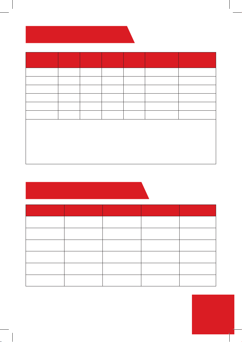
Model *Wattage Voltage Amperage Phase
AT900-03 3 kW 110 27 1 30 10 AWG
AT900-04 3.8 kW 240 16 1 20 12 AWG
AT900-06 6.5 kW 240 27 1 30 10 AWG
AT900-08 8.5 kW 240 36 1 40 6 AWG
AT900-10 10.5 kW 240 44 1 50 6 AWG
AT900-13 13 kW 240 55 1 60 4 AWG
Minimum water ow to activate unit: 0.5 GPM
Nominal water volume: 2.7G/Min
Working pressure: 0.5 -8 bar (7 -115 psi)
Tested pressure: 16 bar (230 psi)
Water connections: 1/2" NPT
Dimensions (in) (H x W x D): 7.3 x 11.8 x 3.55
Weight (Ib): 3.4
* Wattage based on maximum voltage.
Circuit breaker
size
Model Guide - kW Output
Model 240V 208V 110V 120V
AT900-04 3.8 kW 2.8 kW - -
Required wire
size
AT900-06 6.5 kW 4.9 kW - -
AT900-08 8.5 kW 6.4 kW - -
AT900-10 10.5 kW 7.9 kW - -
AT900-13 13.0 kW 9.8 kW - -
AT900-03 - - 3.0 kW 3.5 kW
2
Page 4

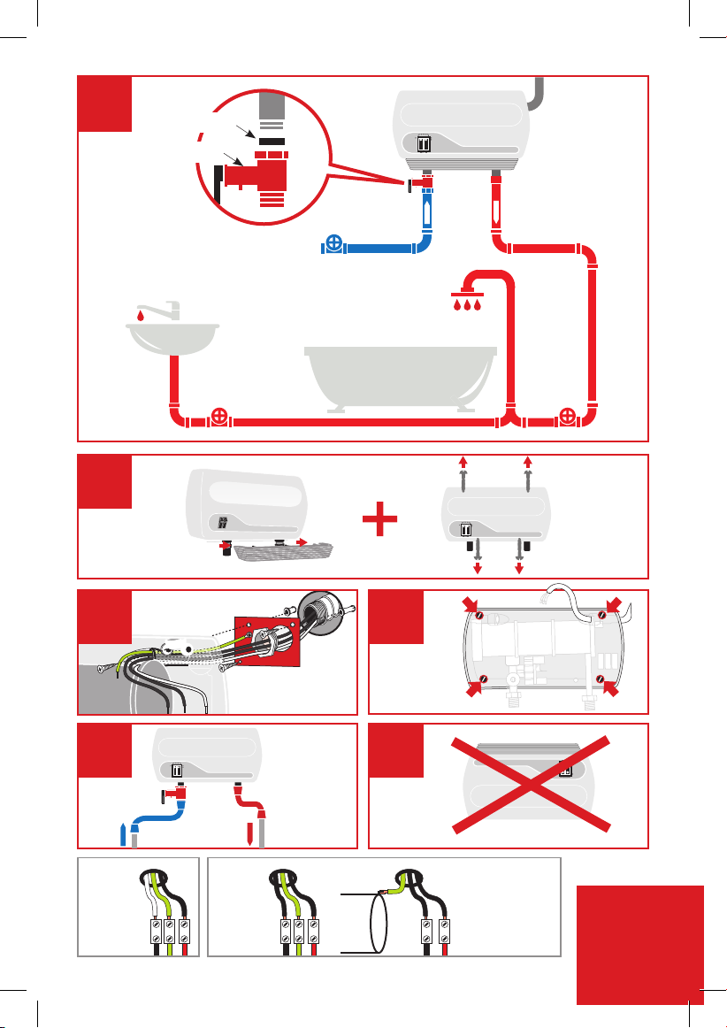
Assembly Instructions
01
Connect the Pressure Relief
Device (PRD) to the unit (Fig1)
Note: IMPORTANT – do not
discard this step. A PRD
must be installed.
Mount unit to wall with 4 screws at the
marked points (Figure 4)
04
05
The appliance must be mounted
horizontally, with water inlets and outlets
at the bottom (Figure 5)
Connect the water inlet hose to the entry point of the heater (left side
inlet), and connect the outlet hose to the water outlet. Use a hose that
can withstand a minimum pressure of 4 bars. Using any other type of
hose will cause damage (Figure 5).
Residential plumbing systems with unstable pressure or pressure
above 5 bar require the application of a pressure stabilizer valve, set
to 4 – 5 bars.
Do not install the appliance with water inlets and outlets at the
top (Figure 6)
02
Remove the appliance
covers (Figure 2).
03
1. Mount ground plate
to wall.
2. Pull wires through.
3. Cut out hole in back
of unit (Right/Left
back) and pass wires
through
(Figure 3)
06
3
Page 5
1
Rubber
PRD
Cold Hot
2
*
3 4
*3a)
3kW
L1 L2 N
L1
N
**
*3b)
3.5-8.5kW
L1GGN
G = Green or Yellow
N = White
L1/L2 = Black
L1G
L2
GNL1
*3c)
8.6-13kW
65
Note: Neutral (N)
does not need to
be connected.
L1
(L2)
L2
N
L1
4
Page 6
07
Run the water ow for
one minute to check for
leakage before connecting
to power.
08
Connect the power cable to the
terminal block.
Caution: The heater must be
grounded.
Reference gure *3 on page 4 and
Electrical diagram on page 6
1009
Reattach the front cover
of the heater and secure
it with 4 screws and then
slide the bottom gray cover
12
Do not install the heater
where it may be subject to
direct sunlight.
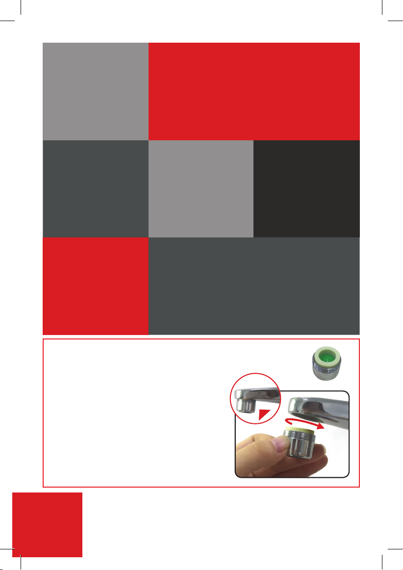
Aerator provided with 3kW models only
Assembly instructions
Make sure that the
appliance is lled with
water before connecting
power. (Repeat step 7)
13
14
For optimal heating performance and proper
operation, the provided 0.5GPM aerator must
be installed to your sink faucet. This will ensure
a continuous ow and consistent, maximum
temperature rise. Output temperature will vary
depending on seasonality and inlet cold water
temperatures
11
When installed outdoors,
the heater must be
placed in sealed
waterproof electrical box.
It is recommended that the appliance
electrical connections be tested once
a year by a qualied technician.
Maximum of 0.5 GPM ow rate is needed for
optimal heating performance
5
Page 7
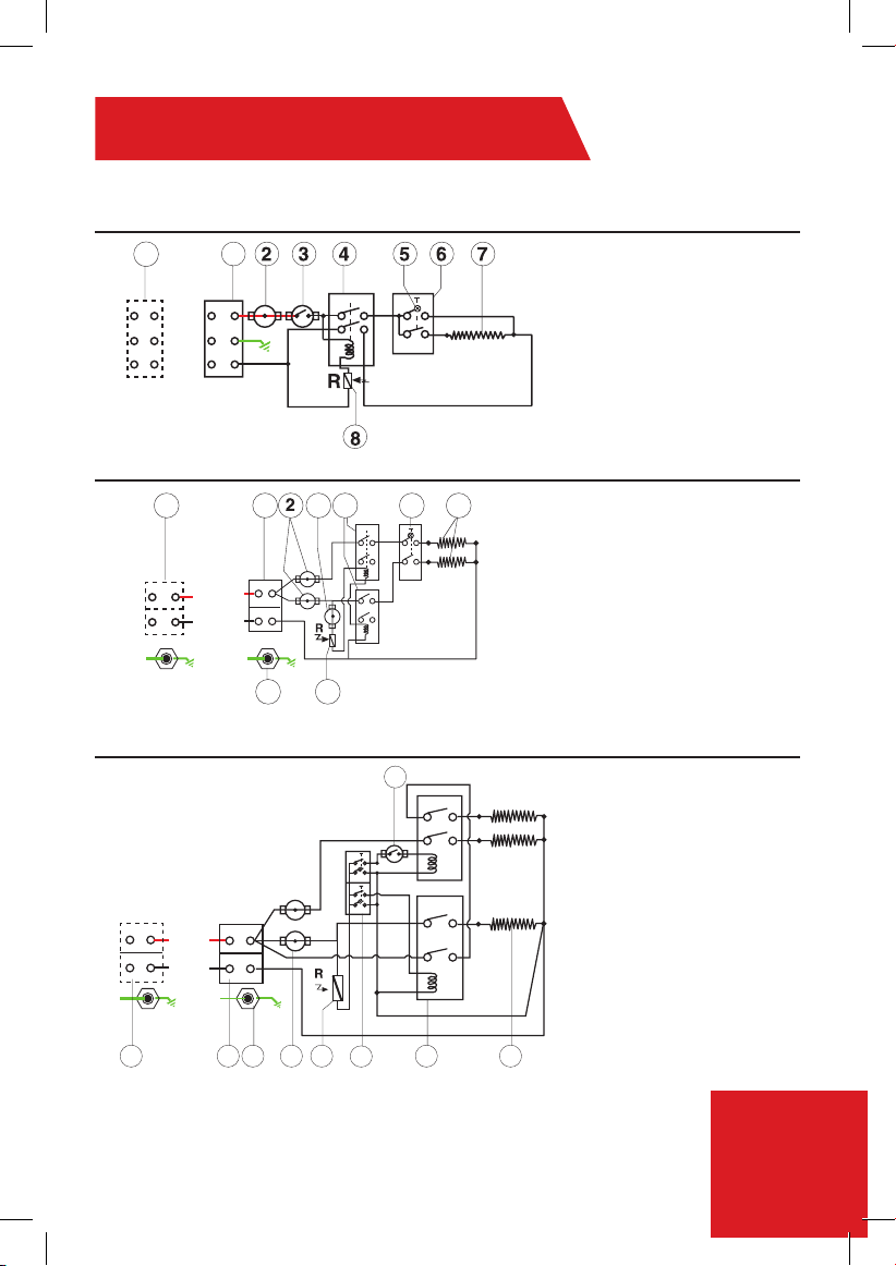
Electrical Diagram
1. 3-3.4kW (110V) - Install Line 1 (L1), E(G)-Ground, N (Neutral)
2. 3.5-8.5kW (240V) - Install Line 1 (L1), E(G)-Ground, Line 2 (L2)
1
L
E(G)
N
1
L1
E(G)
L2(*N)
8.6kW-10.5kW (240V)
L
N
E(G)
L1
L2(*N)
E(G)
10.6kW-13kW (240V)
411 53 6
78
3
1. Terminal block
2. Thermal cut-out with reset
3. Thermal cut-out
4. Relay
5. Light
6. Switch 0- Off
(Option) 1- Low
7. Heating element
8. Read sensor
1. Terminal block
2. Thermal cut-out with reset
3. Thermal Cut out
4. Relay
5. Switch 0- Off
1- Low
2- Medium
3- High
6. Heating element
7. Read sensor
8. EARTH(G) Connection in
the heating canister
L
N
E (G)
L1
L2(*N)
E(G)
1
1
2 7
8
5 64
L1/L2 = Line1/Line2 (Black or Red)
E(G) = Ground (Green/Yellow)
*N = Neutral (White or Silver)
*Neutral acts as Line 2 (L2) for 220V/240V
*Neutral does not have to be connected for 3.5kW-13kW
1. Terminal block
2. Thermostat with reset
3. Thermostat
4. Switches with lights
5. Relay
6. Heating elements
7. Read sensor
8. EARTH(G) Connection in
the heating canister
6
Page 8
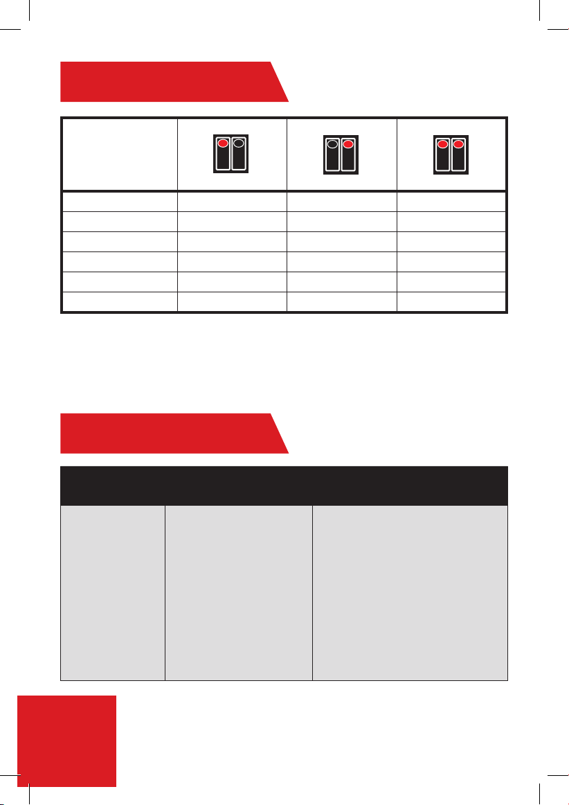
Operation Guide
Low Medium High
MODEL kW kW kW
AT900-03 1 2 3
AT900-04 1.6 2.2 3.8
AT900-06 3 3.5 6.5
AT900-08 3.8 4.7 8.5
AT900-10 5.25 5.25 10.5
AT900-13 4.5 8.5 13
Troubleshooting
PROBLEM ISSUE POSSIBLE CAUSE SOLUTION
Water not hot
enough.
Too much water owing
through the heater.
Reduction in the ambient
temperature.
Water Pressure below of
0.5 bar (7 psi).
Electrical Malfunction.
Reduce the ow rate of the water via
the outlet tap.
Switch to higher temperature setting.
Check if the main water line stop
valve is fully open and that there
are no other restrictions in the water
supply line.
Have the Heater unit check by a
qualied eIectrician or contact your
local authorized distributor.
7
Page 9

Troubleshooting
PROBLEM ISSUE POSSIBLE CAUSE SOLUTION
Water too hot. Not enough water owing
Heater shut off
during use.
Water ceases to
ow.
Water temperature
varies from hot to
cold during use.
No hot water/Unit
is not working.
through the heater.
Increase in the ambient
temperature.
Interruption of main
electrical supply.
Blockage of your hand held
shower head.
No water supply.
Water pressure has
dropped below min. level.
No electrical power.
Low ow rate 0.5 bar (7 psi).
Increase the ow rate via the outlet
tap.
Switch to lower temperature setting.
Check incoming power supply, MCB,
switches and supply cabling.
If problem persists, call your local
authorized distributor for assistance.
Clean or replace your hand held
shower head. Check to see that your
shower head hose is not twisted or
blocked. It is necessary for the hose
to have a free passage of water.
Check if the main water line stop
valve is fully open and that there
are no other restrictions in the water
supply line.
Increase hot water supply.
Check the circuit breaker and check
voltage at the wiring block.
Clean lter screen:
1. Turn circuit breaker off.
2. Open the valve to release pressure
from the unit.
3. Turn circuit breaker on.
If you have an issue and need further assistance,
please call: 1-888-783-6082
8
Page 10

Parts
1. Switches
9
2. PRD
3. Cold water inlet
5. Hot water outlet (to be
connected to the main hot
water pipe)
Page 11

10
Page 12

LIMITED WARRANTY
The terms of this warranty is solely subject to the original owner and is at no time transferable. A
transfer of ownership will result in an immediate termination of this warranty. This warranty is valid
only if product is purchased from an authorized reseller.
Atmor warrants to the original owner that our instant water heaters will be free from defect in
workmanship and material for a period of TWO YEARS from the date of purchase, and free from
leakage for a period of SEVEN YEARS from the date of purchase. Should any part(s) prove to be
defective during this period, Atmor will be responsible for replacement of the defective part(s) only.
Atmor is not responsible for labor charges or any incidental or consequential expenses. Atmor’s
liability is limited to the cost of the product or $1,000.00, whichever is less. Atmor is not an insurer
and the original owner should purchase insurance to cover damage to property or belongings. The
original owner agrees to waive their right to jury trial or to participate in a class action. In addition,
the original owner agrees to waive subordination to the extent a loss is covered by insurance, so
that their insurance company cannot proceed with action against Atmor for recovery of any claims.
Furthermore, all claims must be arbitrated in the state of New Jersey.
Should the owner wish to return the water heater for repair, the owner must rst secure a written
authorization from Atmor. The owner shall be required to show proof of purchase date and to pay
all transportation costs to return the defective part(s) or water heater for repair or replacement.
Warranty is void if: (i) water heater has been installed or used improperly; (ii) design has been altered
in any way; (iii) water heater has been installed and/or serviced by someone other than a licensed
electrician ; (iv) or if the water heater has been
installed or used in contradiction to installation
instructions, applicable laws and/or ordinances.
A full and complete version of this warranty is
available on the online, www.atmorusa.com, or
upon request from an Atmor representative
Distributed by:
PARAGON GROUP USA LLC
Englewood, NJ 07631
USA
Phone: 1-888-783-6082
Email: info@paragongroupusa.com
Web: www.atmorusa.com
Page 13

Hot Water on Demand
Instalación y guía de funcionamiento
Serie InLine 900
3kW-13kW
www.atmor.net
Page 14

Instrucciones de seguridad
Información técnica
Guía del modelo – Salida en kW
2
Modelo *Vataje Voltaje Amperaje Fase
Tamaño del
disyuntor
Tamaño de cable
requerido
AT900-03 3 kW 110 27 1 30 10 AWG
AT900-04 3.8 kW 240 16 1 20 12 AWG
AT900-06 6.5 kW 240 27 1 30 10 AWG
AT900-08 8.5 kW 240 36 1 40 6 AWG
AT900-10 10.5 kW 240 44 1 50 6 AWG
AT900-13 13 kW 240 55 1 60 4 AWG
Flujo mínimo de agua para activar la unidad: 0.5 GPM
Volumen de agua nominal: 0.11 galones (0.42 l)
Presión de funcionamiento: de 0.5 a 8 bares (de 7 a 115 psi)
Presión probada: 16 bares (230 psi)
Conexiones de agua: 1/2" NPT
Dimensiones (pulg.) (A x A x P): 7.3 x 11.8 x 3.55
Peso (libras): 3.4
Modelo 240 V 208 V 110 V 120 V
AT900-04 3.8 kW 2.8 kW - -
AT900-06 6.5 kW 4.9 kW - -
AT900-08 8.5 kW 6.4 kW - -
AT900-10 10.5 kW 7.9 kW - -
AT900-13 13.0 kW 9.8 kW - -
AT900-03 - - 3.0 kW 3.5 kW
* El vataje se basa en el voltaje máximo.
DESCRIPCIÓN GENERAL
Este manual se debe leer atentamente antes de intentar instalar el calentador de agua. Si usted no cumple las reglas de
seguridad o las instrucciones detalladas en este manual, la unidad puede no funcionar adecuadamente y puede causar daños a
la propiedad, lesiones corporales graves o la muerte.
Atmor no será responsable de los daños ocasionados por no cumplir las instrucciones de instalación y funcionamiento detallados
en este manual o por el uso inadecuado. El uso inadecuado incluye el uso de este artefacto para calentar cualquier líquido que no
sea agua. No cumplir las instrucciones de instalación y funcionamiento o usar el artefacto de manera
inadecuada anula la garantía. Nunca retire la cubierta de la unidad a menos que la electricidad esté
desconectada.
01
El calentador de agua debe
ser instalado por un electricista
certificado y en conformidad con
todas las regulaciones locales en
materia de electricidad y edificios.
04
El calentador se debe
instalar de acuerdo con las
instrucciones de instalación (ver
las figuras).
02
Precaución: el artefacto se debe
conectar a tierra.
05
La instalación de plomería se
debe completar antes de la
instalación eléctrica.
03
06
Se debe instalar un disyuntor
dedicado en el panel de distribución
de la alimentación.
El calentador funciona a
una tasa de flujo mínima de
0.5 galones/minuto.
07
La instalación de plomería
requiere tuberías reforzadas o
metálicas que puedan soportar
una presión mínima de 8
bares. (Otros tipos de tuberías
causarán daños).
08
No instale el calentador donde
pueda estar expuesto a la luz
solar directa, la lluvia o el rocío
constante de agua.
09
Siempre comuníquese
con su profesional local
autorizado y certificado para
realizar el mantenimiento.
1
Page 15

Información técnica
Guía del modelo – Salida en kW
2
Modelo *Vataje Voltaje Amperaje Fase
Tamaño del
disyuntor
Tamaño de cable
requerido
AT900-03 3 kW 110 27 1 30 10 AWG
AT900-04 3.8 kW 240 16 1 20 12 AWG
AT900-06 6.5 kW 240 27 1 30 10 AWG
AT900-08 8.5 kW 240 36 1 40 6 AWG
AT900-10 10.5 kW 240 44 1 50 6 AWG
AT900-13 13 kW 240 55 1 60 4 AWG
Flujo mínimo de agua para activar la unidad: 0.5 GPM
Volumen de agua nominal: 0.11 galones (0.42 l)
Presión de funcionamiento: de 0.5 a 8 bares (de 7 a 115 psi)
Presión probada: 16 bares (230 psi)
Conexiones de agua: 1/2" NPT
Dimensiones (pulg.) (A x A x P): 7.3 x 11.8 x 3.55
Peso (libras): 3.4
Modelo 240 V 208 V 110 V 120 V
AT900-04 3.8 kW 2.8 kW - -
AT900-06 6.5 kW 4.9 kW - -
AT900-08 8.5 kW 6.4 kW - -
AT900-10 10.5 kW 7.9 kW - -
AT900-13 13.0 kW 9.8 kW - -
AT900-03 - - 3.0 kW 3.5 kW
* El vataje se basa en el voltaje máximo.
2.7G/Min
Page 16

Instrucciones de ensamblaje
01
Conecte el dispositivo de alivio de
presión a la unidad (Fig. 1).
Nota: IMPORTANTE – No omita
este paso. Se debe instalar un
dispositivo de alivio de presión.
Instale la unidad con los 4 tornillos en los puntos
marcados (Figura 4).
04
05
El artefacto se debe instalar horizontalmente, con
las entradas y salidas de agua en la parte inferior
(Figura 5).
Conecte la manguera de entrada de agua al punto de entrada del calentador (entrada del
lado izquierdo) y conecte la manguera de salida a la salida de agua. Use una manguera
que pueda soportar una presión mínima de 4 bares. El uso de cualquier otro tipo de
manguera causará daños (Figura 5).
Los sistemas de plomería residenciales con una presión inestable o una presión que
supere los 5 bares requieren la aplicación de una válvula estabilizadora de presión,
fijada en 4 a 5 bares.
No instale el artefacto con las entradas y salidas de agua en la parte superior
(Figura 6).
02
Retire las cubiertas del
artefacto (Figura 2).
03
1. Instale la placa de tierra a
la pared.
2. Jale los cables.
3. Corte el orificio en la parte
posterior de la unidad
(Derecha/Izquierda posterior)
y pase los cables
(Figura 3).
06
3
Page 17

1
Goma
Dispositivo de
alivio de
presión
Frío Caliente
2
*
3 4
*3a)
3kW
L1 L2 N
L1
N
G = Verde o amarillo
N = Blanco
L1/L2 = Negro
**
*3b)
3.5-8.5kW
L1GGN
65
*3c)
8.6-13kW
L1G
L2
GNL1
(L2)
L2
N
Nota: el neutro
(N) no requiere
conexión.
L1
L1
4
Page 18

Conecte el cable de alimentación al bloque
6
Diagrama eléctrico
1. Bloque de terminales
2. Interruptor térmico con reajuste
3. Interruptor térmico
4. Relé
5. Luz
6. Interruptor 0- Apagado
(Opción) 1- Bajo
7. Resistencia
8. Sensor de lectura
1. Bloque de terminales
2. Interruptor térmico con reajuste
3. Interruptor térmico
4. Relé
5. Interruptor 0- Apagado
1- Bajo
2- Medio
3- Alto
6. Resistencia
7. Sensor de lectura
8. TIERRA (G) Conexión en el
recipiente calentador
411 53 6
198
L1
L2(*N)
E(G)
L
N
E(G)
1
1
L
E(G)
N
L1
E(G)
L2(*N)
1. Bloque de terminales
2. Termostato con reajuste
3. Termostato
4. Interruptores con luces
5. Relé
6. Resistencias
7. Sensor de lectura
8. TIERRA (G) Conexión en el
recipiente calentador
L1
L2(*N)
E(G)
5 64
1 2 7
3
L
N
E (G)
8
1
8.6kW-10.5kW (240V)
10.6kW-13kW (240V)
1. 3-3.4 kW (110 V) - Instalar Línea 1 (L1), E(G)-Tierra, N (Neutro)
2. 3.5-8.5 kW (240 V) - Instalar Línea 1 (L1), E(G)-Tierra, Línea 2 (L2)
L1/L2 = Línea 1/Línea 2 (Negro o Rojo)
E(G) = Tierra (Verde/Amarillo)
*N = Neutro (Blanco o Plata)
*El neutro actúa como Línea 2 (L2) para 220 V/240 V
*El neutro no requiere conexión para 3.5 kW-13 kW
de terminales.
07
Deje correr el agua durante un
minuto para verificar si hay fugas
antes de conectar el artefacto al
suministro eléctrico.
Vuelva a colocar la cubierta frontal del
calentador y asegúrela con 4 tornillos, y luego
deslice la cubierta gris inferior.
08
Precaución: el calentador debe estar
conectado a tierra.
Consulte la figura 3 en la página 4 y el
diagrama eléctrico en la página 6.
1009
Asegúrese de que el artefacto
esté lleno de agua antes de
conectar el suministro eléctrico.
(Repita el paso 7).
11 12
Cuando el sistema se instala al
aire libre, el calentador se debe
colocar en una caja eléctrica
sellada a prueba de agua.
Se recomienda que las conexiones eléctricas del artefacto
sean probadas una vez al año por un técnico certificado.
13
5
No instale el calentador donde
pueda estar expuesto a la luz
solar directa.
Page 19

Diagrama eléctrico
1. 3-3.4 kW (110 V) - Instalar Línea 1 (L1), E(G)-Tierra, N (Neutro)
2. 3.5-8.5 kW (240 V) - Instalar Línea 1 (L1), E(G)-Tierra, Línea 2 (L2)
1
L
E(G)
N
1
L1
E(G)
L2(*N)
8.6kW-10.5kW (240V)
L
N
E(G)
L1
L2(*N)
E(G)
10.6kW-13kW (240V)
L
N
E (G)
L1
L2(*N)
E(G)
411 53 6
198
3
1. Bloque de terminales
2. Interruptor térmico con reajuste
3. Interruptor térmico
4. Relé
5. Luz
6. Interruptor 0- Apagado
(Opción) 1- Bajo
7. Resistencia
8. Sensor de lectura
1. Bloque de terminales
2. Interruptor térmico con reajuste
3. Interruptor térmico
4. Relé
5. Interruptor 0- Apagado
1- Bajo
2- Medio
3- Alto
6. Resistencia
7. Sensor de lectura
8. TIERRA (G) Conexión en el
recipiente calentador
1. Bloque de terminales
2. Termostato con reajuste
3. Termostato
4. Interruptores con luces
5. Relé
6. Resistencias
7. Sensor de lectura
8. TIERRA (G) Conexión en el
recipiente calentador
1 2 7
1
8
L1/L2 = Línea 1/Línea 2 (Negro o Rojo)
E(G) = Tierra (Verde/Amarillo)
*N = Neutro (Blanco o Plata)
*El neutro actúa como Línea 2 (L2) para 220 V/240 V
*El neutro no requiere conexión para 3.5 kW-13 kW
5 64
6
Page 20

Guía de funcionamiento
Resolución de problemas
8
PROBLEMA CAUSA POSIBLE SOLUCIÓN
El agua está No fluye suficiente agua por
demasiado caliente. el calentador.
La temperatura ambiente
aumentó.
Incrementar la tasa de flujo mediante la
llave de salida.
Cambiar a un ajuste de temperatura
más bajo.
El calentador se
apaga durante
el uso.
Interrupción del
suministro eléctrico.
Revisar el suministro de energía,
disyuntor, interruptores y cableado.
Si el problema persiste, comuníquese
con su distribuidor local autorizado para
obtener asistencia.
El agua deja de
correr.
Bloqueo del cabezal de la
ducha.
Interrupción del suministro
de agua.
Limpiar o reemplazar el cabezal de la
ducha. Verificar que la manguera del
cabezal de ducha no esté retorcida o
bloqueada. La manguera debe tener un
libre paso de agua.
Verificar que la válvula de cierre de la
línea de agua esté completamente abierta
y que no existan otras restricciones en la
línea de suministro de agua.
La temperatura del
agua varía de caliente
a fría durante el uso.
La presión del agua ha
caído por debajo del nivel
mínimo.
Aumentar el suministro de agua
caliente.
No sale agua
caliente/La unidad
no funciona.
Falta de energía eléctrica.
Tasa de flujo baja, 0.5 bares
(7 psi).
Verificar el disyuntor y el voltaje en el
bloque de cableado.
Limpiar la rejilla del filtro:
1. Apagar el disyuntor.
2. Abrir la válvula para liberar la presión
de la unidad.
3. Encender el disyuntor.
Si tiene un problema y necesita más asistencia,
llame al: 1-888-783-6082
Bajo Medio Alto
MODELO kW kW kW
AT900-03 1 2 3
AT900-04 1.6 2.2 3.8
AT900-06 3 3.5 6.5
AT900-08 3.8 4.7 8.5
AT900-10 5.25 5.25 10.5
AT900-13 4.5 8.5 13
Resolución de problemas
PROBLEMA CAUSA POSIBLE SOLUCIÓN
El agua no está lo
suficientemente
caliente.
Fluye demasiada agua por
el calentador.
La temperatura ambiente
disminuyó.
La presión del agua no
alcanza los 0.5 bares (7 psi).
Desperfecto eléctrico.
7
Reducir la tasa de flujo del agua
mediante la llave de salida.
Cambiar a un ajuste de temperatura
más alto.
Verificar que la válvula de cierre de la
línea de agua esté completamente abierta
y que no existan otras restricciones en la
línea de suministro de agua.
Hacer que un electricista certificado
revise el calentador o comunicarse con
su distribuidor local autorizado.
Page 21

Resolución de problemas
PROBLEMA CAUSA POSIBLE SOLUCIÓN
El agua está No fluye suficiente agua por
demasiado caliente. el calentador.
La temperatura ambiente
aumentó.
El calentador se
apaga durante
el uso.
El agua deja de
correr.
La temperatura del
agua varía de caliente
a fría durante el uso.
No sale agua
caliente/La unidad
no funciona.
Interrupción del
suministro eléctrico.
Bloqueo del cabezal de la
ducha.
Interrupción del suministro
de agua.
La presión del agua ha
caído por debajo del nivel
mínimo.
Falta de energía eléctrica.
Tasa de flujo baja, 0.5 bares
(7 psi).
Incrementar la tasa de flujo mediante la
llave de salida.
Cambiar a un ajuste de temperatura
más bajo.
Revisar el suministro de energía,
disyuntor, interruptores y cableado.
Si el problema persiste, comuníquese
con su distribuidor local autorizado para
obtener asistencia.
Limpiar o reemplazar el cabezal de la
ducha. Verificar que la manguera del
cabezal de ducha no esté retorcida o
bloqueada. La manguera debe tener un
libre paso de agua.
Verificar que la válvula de cierre de la
línea de agua esté completamente abierta
y que no existan otras restricciones en la
línea de suministro de agua.
Aumentar el suministro de agua
caliente.
Verificar el disyuntor y el voltaje en el
bloque de cableado.
Limpiar la rejilla del filtro:
1. Apagar el disyuntor.
2. Abrir la válvula para liberar la presión
de la unidad.
3. Encender el disyuntor.
Si tiene un problema y necesita más asistencia,
llame al: 1-888-783-6082
8
Page 22

Piezas
10
1. Interruptores
9
2. Dispositivo de
alivio de presión
3. Entrada de
agua fría
5. Salida de agua caliente
(para conectar a la tubería
de agua caliente)
Page 23

10
Page 24

GARANTÍA LIMITADA
Atmor garantiza al propietario original de nuestros calentadores de agua instantáneos la ausencia de
defectos de fabricación y material durante un período de DOS AÑOS a partir de la fecha de compra, y la
ausencia de fugas durante un período de SIETE AÑOS a partir de la fecha de compra. Si alguna pieza
resultara defectuosa durante este período, Atmor será responsable del reemplazo de la pieza defectuosa
únicamente. Atmor no se responsabilizará por los costos de mano de obra o cualquier gasto incidental o
consecuente.
Si el propietario desea devolver el calentador para su reparación, el propietario primero debe obtener una
autorización escrita de Atmor. Se requiere que el propietario muestre una prueba de la fecha de compra y
pague todos los costos de transporte para devolver la pieza defectuosa o el calentador para su reparación
o reemplazo. La garantía no será válida si: (i) el calentador de agua ha sido instalado o usado de manera
inadecuada; (ii) el diseño ha sido alterado de cualquier manera; (iii) la instalación o el mantenimiento del
calentador estuvo a cargo de una persona distinta de un electricista habilitado; (iv) o si el calentador ha sido
instalado o usado en contradicción con las instrucciones de instalación, las leyes u ordenanzas aplicables.
GARANTÍA LIMITADA
Los términos de esta garantía están únicamente sujetos al propietario original y en ningún momento
son transferibles. Una transferencia de propiedad resultará en la terminación inmediata de esta
garantía. Esta garantía es válida sólo si el producto se adquiere de un distribuidor autorizado.
Atmor garantiza al propietario original de nuestros calentadores de agua instantáneos la ausencia
de defectos de fabricación y material durante un período de DOS AÑOS a partir de la fecha de
compra, y la ausencia de fugas durante un período de SIETE AÑOS a partir de la fecha de compra.
Si alguna pieza resultara defectuosa durante este período, Atmor será responsable del reemplazo
de la pieza defectuosa únicamente. Atmor no se responsabilizará por los costos de mano de obra
o cualquier gasto incidental o consecuente. La responsabilidad de Atmor se limita al costo del
producto o $ 1,000.00, lo que sea menor. Atmor no es una aseguradora y el propietario original
debe comprar un seguro para cubrir los daños a la propiedad o pertenencias. El propietario original
se compromete a renunciar a su derecho a juicio por jurado oa participar en una acción colectiva.
Además, el propietario original se compromete a renunciar a la subordinación en la medida en
que una pérdida está cubierta por el seguro, de modo que su compañía de seguros no puede
proceder con la acción contra Atmor para la recuperación de las reclamaciones. Además, todas las
reclamaciones deben ser arbitradas en el estado de Nueva Jersey.
Si el propietario desea devolver el calentador para su reparación, el propietario primero debe obtener
una autorización escrita de Atmor. Se requiere que el propietario muestre una prueba de la fecha
de compra y pague todos los costos de transporte para devolver la pieza defectuosa o el calentador
para su reparación o reemplazo. La garantía no será válida si: (i) el calentador de agua ha sido
instalado o usado de manera inadecuada; (ii) el
diseño ha sido alterado de cualquier manera; (iii)
la instalación o el mantenimiento del calentador
estuvo a cargo de una persona distinta de un
electricista habilitado; (iv) o si el calentador ha
sido instalado o usado en contradicción con
las instrucciones de instalación, las leyes u
ordenanzas aplicables.
Una versión completa de esta garantía está
disponible en línea, www.atmorusa.com, o bajo
petición de un representante de Atmor.
Distribuido por:
PARAGON GROUP USA LLC
15 Engle Street, 3rd Floor
Englewood, NJ 07631
1-888-783-6082
Nuestro personal está preparado para asistirlo.
¡ALTO!
¡Primero llámenos y deje que
nuestro equipo de asistencia lo ayude!
NO DEVUELVA EL CALENTADOR
A LA TIENDA
¿Tiene preguntas acerca de su unidad
o necesita asistencia?
Llame al:
1-888-783-6082
o envíe un correo electrónico a:
info@paragongroupusa.com
De lunes a viernes, de
9 a.m. a 5 p.m. Hora Estándar del Este
P.N. 115045C
P.N. 197335C
 Loading...