

Atmor AT90008, AT90013, AT90010, AT90004, AT90006 User Manual
...
Hot Water on Demand
Installation and Operation Guide
900 Series InLine
3kW-13kW
www.atmor.net

Safety Instructions
OVERVIEW
This manual must be read carefully before attempting to install the water heater. If you do not follow the safety
rules or the instructions outlined in this manual, the unit may not operate properly and it could cause property
damage, serious bodily injury or death.
Atmor will not be liable for any damages because of failure to comply with the installation and operating
instructions outlined in this manual or because of improper use. Improper use includes the use of this appliance
to heat any liquid other than water. Failure to comply with the installation and operating instructions or
improper use voids the warranty. Never remove the unit’s cover unless the electricity is turned off.
01
The water heater must
be installed by a licensed
electrician and in compliance
with all local electrical and
building regulations.
04
The heater must be installed
according to the installation
instructions (see gures).
07
The plumbing installation
requires metal or reinforced
pipes that can withstand a
minimum pressure of 8 bar.
(Other types of pipes will
cause damage.)
02
Caution: The appliance must
be grounded.
05
The plumbing installation
must be completed before
the electrical installation.
08
Do not install the heater
where it may be subjected
to direct sunlight, rain and/
or a constant spray of
water.
03
A dedicated circuit breaker
must be installed on the
power distribution panel.
06
The heater operates at a
minimum water ow rate of
0.5 gallon/minute.
09
Always contact your
local authorized licensed
proffessional for service.
1
Technical Information
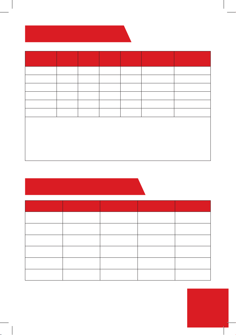
Model *Wattage Voltage Amperage Phase
AT900-03 3 kW 110 27 1 30 10 AWG
AT900-04 3.8 kW 240 16 1 20 12 AWG
AT900-06 6.5 kW 240 27 1 30 10 AWG
AT900-08 8.5 kW 240 36 1 40 6 AWG
AT900-10 10.5 kW 240 44 1 50 6 AWG
AT900-13 13 kW 240 55 1 60 4 AWG
Minimum water ow to activate unit: 0.5 GPM
Nominal water volume: 2.7G/Min
Working pressure: 0.5 -8 bar (7 -115 psi)
Tested pressure: 16 bar (230 psi)
Water connections: 1/2" NPT
Dimensions (in) (H x W x D): 7.3 x 11.8 x 3.55
Weight (Ib): 3.4
* Wattage based on maximum voltage.
Circuit breaker
size
Model Guide - kW Output
Model 240V 208V 110V 120V
AT900-04 3.8 kW 2.8 kW - -
Required wire
size
AT900-06 6.5 kW 4.9 kW - -
AT900-08 8.5 kW 6.4 kW - -
AT900-10 10.5 kW 7.9 kW - -
AT900-13 13.0 kW 9.8 kW - -
AT900-03 - - 3.0 kW 3.5 kW
2

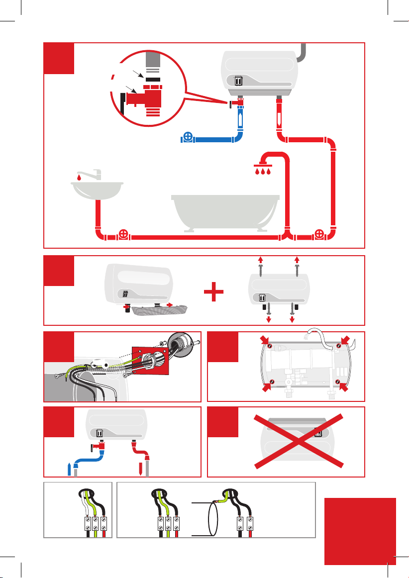
Assembly Instructions
01
Connect the Pressure Relief
Device (PRD) to the unit (Fig1)
Note: IMPORTANT – do not
discard this step. A PRD
must be installed.
Mount unit to wall with 4 screws at the
marked points (Figure 4)
04
05
The appliance must be mounted
horizontally, with water inlets and outlets
at the bottom (Figure 5)
Connect the water inlet hose to the entry point of the heater (left side
inlet), and connect the outlet hose to the water outlet. Use a hose that
can withstand a minimum pressure of 4 bars. Using any other type of
hose will cause damage (Figure 5).
Residential plumbing systems with unstable pressure or pressure
above 5 bar require the application of a pressure stabilizer valve, set
to 4 – 5 bars.
Do not install the appliance with water inlets and outlets at the
top (Figure 6)
02
Remove the appliance
covers (Figure 2).
03
1. Mount ground plate
to wall.
2. Pull wires through.
3. Cut out hole in back
of unit (Right/Left
back) and pass wires
through
(Figure 3)
06
3
1
Rubber
PRD
Cold Hot
2
*
3 4
*3a)
3kW
L1 L2 N
L1
N
**
*3b)
3.5-8.5kW
L1GGN
G = Green or Yellow
N = White
L1/L2 = Black
L1G
L2
GNL1
*3c)
8.6-13kW
65
Note: Neutral (N)
does not need to
be connected.
L1
(L2)
L2
N
L1
4
07
Run the water ow for
one minute to check for
leakage before connecting
to power.
08
Connect the power cable to the
terminal block.
Caution: The heater must be
grounded.
Reference gure *3 on page 4 and
Electrical diagram on page 6
1009
Reattach the front cover
of the heater and secure
it with 4 screws and then
slide the bottom gray cover
12
Do not install the heater
where it may be subject to
direct sunlight.
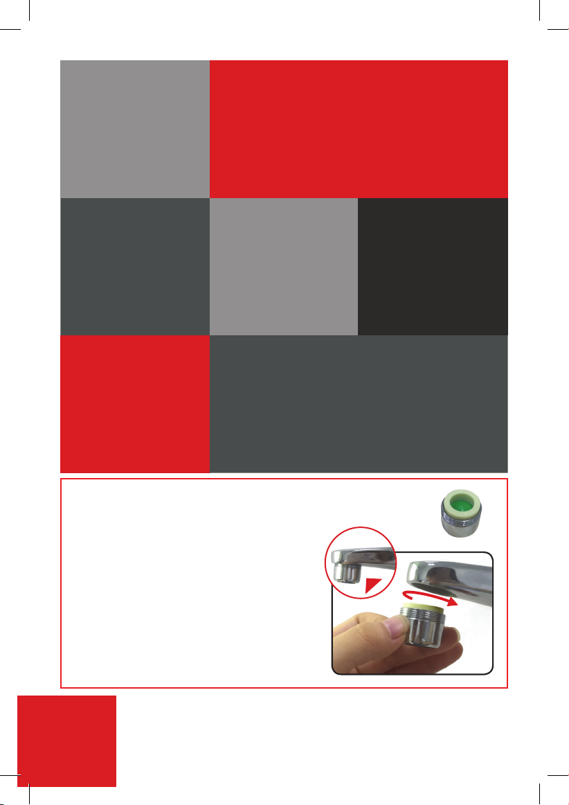
Aerator provided with 3kW models only
Assembly instructions
Make sure that the
appliance is lled with
water before connecting
power. (Repeat step 7)
13
14
For optimal heating performance and proper
operation, the provided 0.5GPM aerator must
be installed to your sink faucet. This will ensure
a continuous ow and consistent, maximum
temperature rise. Output temperature will vary
depending on seasonality and inlet cold water
temperatures
11
When installed outdoors,
the heater must be
placed in sealed
waterproof electrical box.
It is recommended that the appliance
electrical connections be tested once
a year by a qualied technician.
Maximum of 0.5 GPM ow rate is needed for
optimal heating performance
5
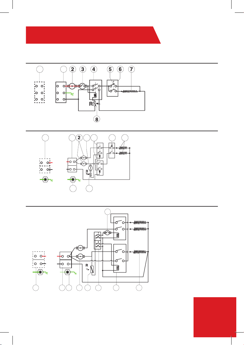
Electrical Diagram
1. 3-3.4kW (110V) - Install Line 1 (L1), E(G)-Ground, N (Neutral)
2. 3.5-8.5kW (240V) - Install Line 1 (L1), E(G)-Ground, Line 2 (L2)
1
L
E(G)
N
1
L1
E(G)
L2(*N)
8.6kW-10.5kW (240V)
L
N
E(G)
L1
L2(*N)
E(G)
10.6kW-13kW (240V)
411 53 6
78
3
1. Terminal block
2. Thermal cut-out with reset
3. Thermal cut-out
4. Relay
5. Light
6. Switch 0- Off
(Option) 1- Low
7. Heating element
8. Read sensor
1. Terminal block
2. Thermal cut-out with reset
3. Thermal Cut out
4. Relay
5. Switch 0- Off
1- Low
2- Medium
3- High
6. Heating element
7. Read sensor
8. EARTH(G) Connection in
the heating canister
L
N
E (G)
L1
L2(*N)
E(G)
1
1
2 7
8
5 64
L1/L2 = Line1/Line2 (Black or Red)
E(G) = Ground (Green/Yellow)
*N = Neutral (White or Silver)
*Neutral acts as Line 2 (L2) for 220V/240V
*Neutral does not have to be connected for 3.5kW-13kW
1. Terminal block
2. Thermostat with reset
3. Thermostat
4. Switches with lights
5. Relay
6. Heating elements
7. Read sensor
8. EARTH(G) Connection in
the heating canister
6
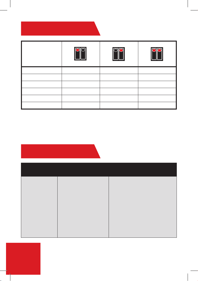
Operation Guide
Low Medium High
MODEL kW kW kW
AT900-03 1 2 3
AT900-04 1.6 2.2 3.8
AT900-06 3 3.5 6.5
AT900-08 3.8 4.7 8.5
AT900-10 5.25 5.25 10.5
AT900-13 4.5 8.5 13
Troubleshooting
PROBLEM ISSUE POSSIBLE CAUSE SOLUTION
Water not hot
enough.
Too much water owing
through the heater.
Reduction in the ambient
temperature.
Water Pressure below of
0.5 bar (7 psi).
Electrical Malfunction.
Reduce the ow rate of the water via
the outlet tap.
Switch to higher temperature setting.
Check if the main water line stop
valve is fully open and that there
are no other restrictions in the water
supply line.
Have the Heater unit check by a
qualied eIectrician or contact your
local authorized distributor.
7
 Loading...