

Atmel SAM L22 Xplained Pro User Manual
SMART ARM-based Microcontrollers
SAM L22 Xplained Pro
USER GUIDE
Preface
The Atmel® SAM L22 Xplained Pro evaluation kit is a hardware platform to
evaluate the ATSAML22N18A microcontroller.
Supported by the Atmel Studio integrated development platform, the kit
provides easy access to the features of the Atmel ATSAML22N18A and
explains how to integrate the device in a custom design.
The Xplained Pro MCU series evaluation kits include an on-board
Embedded Debugger, and no external tools are necessary to program or
debug the ATSAML22N18A.
The Xplained Pro extension kits offers additional peripherals to extend the
features of the board and ease the development of custom designs.
Atmel-42474B-SAM-L22-Xplained-Pro_User Guide-12/2015

Table of Contents
Preface............................................................................................................................ 1
1. Introduction................................................................................................................4
1.1. Features....................................................................................................................................... 4
1.2. Kit Overview................................................................................................................................. 4
2. Getting Started...........................................................................................................6
2.1. Xplained Pro Quick Start.............................................................................................................. 6
2.2. Design Documentation and Relevant Links................................................................................. 6
3. Xplained Pro.............................................................................................................. 8
3.1. Embedded Debugger................................................................................................................... 8
3.2. Xplained Pro Analog Module (XAM).............................................................................................9
3.2.1. Overview........................................................................................................................9
3.2.2. EDBG Interface..............................................................................................................9
3.2.3. Sample Rate................................................................................................................ 10
3.2.4. Measurement Ranges and Accuracy...........................................................................10
3.3. Hardware Identification System..................................................................................................10
3.4. Power Sources........................................................................................................................... 11
3.5. Xplained Pro Headers and Connectors......................................................................................12
3.5.1. Xplained Pro Standard Extension Header................................................................... 12
3.5.2. Xplained Pro Segment LCD Connector....................................................................... 13
3.5.3. Xplained Pro Power Header........................................................................................ 14
4. Hardware User Guide..............................................................................................15
4.1. Power Distribution...................................................................................................................... 15
4.2. Connectors................................................................................................................................. 15
4.2.1. Xplained Pro Standard Extension Headers................................................................. 16
4.2.2. Segment LCD Connector.............................................................................................19
4.2.3. Arduino Connector Footprint........................................................................................21
4.2.4. USB............................................................................................................................. 23
4.2.5. Cortex Debug Connector............................................................................................. 23
4.2.6. Current Measurement Header..................................................................................... 24
4.3. Peripherals................................................................................................................................. 24
4.3.1. Crystal..........................................................................................................................24
4.3.2. Mechanical Buttons..................................................................................................... 24
4.3.3. LED..............................................................................................................................25
4.3.4. QTouch Button.............................................................................................................25
4.3.5. Backup Super Capacitor..............................................................................................25
4.3.6. Crypto Device.............................................................................................................. 26
4.3.7. Tamper Detection.........................................................................................................26
4.4. Embedded Debugger Implementation........................................................................................27
4.4.1. Serial Wire Debug........................................................................................................27
4.4.2. Virtual COM Port..........................................................................................................27
4.4.3. Atmel Data Gateway Interface.....................................................................................27
Atmel SAM L22 Xplained Pro [USER GUIDE]
Atmel-42474B-SAM-L22-Xplained-Pro_User Guide-12/2015
2

4.4.4. XAM Configuration.......................................................................................................28
4.5. Kit Modifications......................................................................................................................... 29
4.5.1. Operation at Other Voltages........................................................................................ 33
5. Appendix..................................................................................................................35
5.1. Getting Started with IAR.............................................................................................................35
5.2. Connecting a SAM-ICE to an Xplained Pro Board..................................................................... 38
6. Hardware Revision History and Known Issues........................................................40
6.1. Identifying Product ID and Revision........................................................................................... 40
6.2. Revision 4...................................................................................................................................40
6.3. Revision 2...................................................................................................................................40
6.3.1. Pin-out Changes.......................................................................................................... 41
6.3.2. CryptoAuthentication Device....................................................................................... 41
6.3.3. Assembly Drawings..................................................................................................... 41
7. Document Revision History..................................................................................... 44
8. Evaluation Board/kit Important Notice..................................................................... 45
Atmel SAM L22 Xplained Pro [USER GUIDE]
Atmel-42474B-SAM-L22-Xplained-Pro_User Guide-12/2015
3

1. Introduction
1.1. Features
• ATSAML22N18A microcontroller
• One mechanical reset button
• One mechanical programmable button
• Xplained Pro segment LCD connector
– Eight COM signals
– Twenty-seven SEG signals
– Six touch signals
• One QTouch® button
• One yellow user LED
• Backup super capacitor
• 32.768kHz crystal
• USB interface, device only
• Three Xplained Pro extension headers
• Embedded Debugger
– Auto-ID for board identification in Atmel Studio
– One yellow status LED
– One green board power LED
– Symbolic debug of complex data types including scope information
– Programming and debugging, including power measurements
– Data Gateway Interface: SPI, I2C, four GPIOs
– Virtual COM port (CDC)
• Embedded current measurement circuitry, with Atmel Data Visualizer support for data visualization
• USB powered
• Supported with application examples in Atmel Software Framework
1.2. Kit Overview
The Atmel SAM L22 Xplained Pro evaluation kit is a hardware platform to evaluate the Atmel
ATSAML22N18A.
The kit offers a set of features that enables the ATSAML22N18A user to get started with the SAM L
peripherals right away and to get an understanding of how to integrate the device in their own design.
Atmel SAM L22 Xplained Pro [USER GUIDE]
Atmel-42474B-SAM-L22-Xplained-Pro_User Guide-12/2015
4
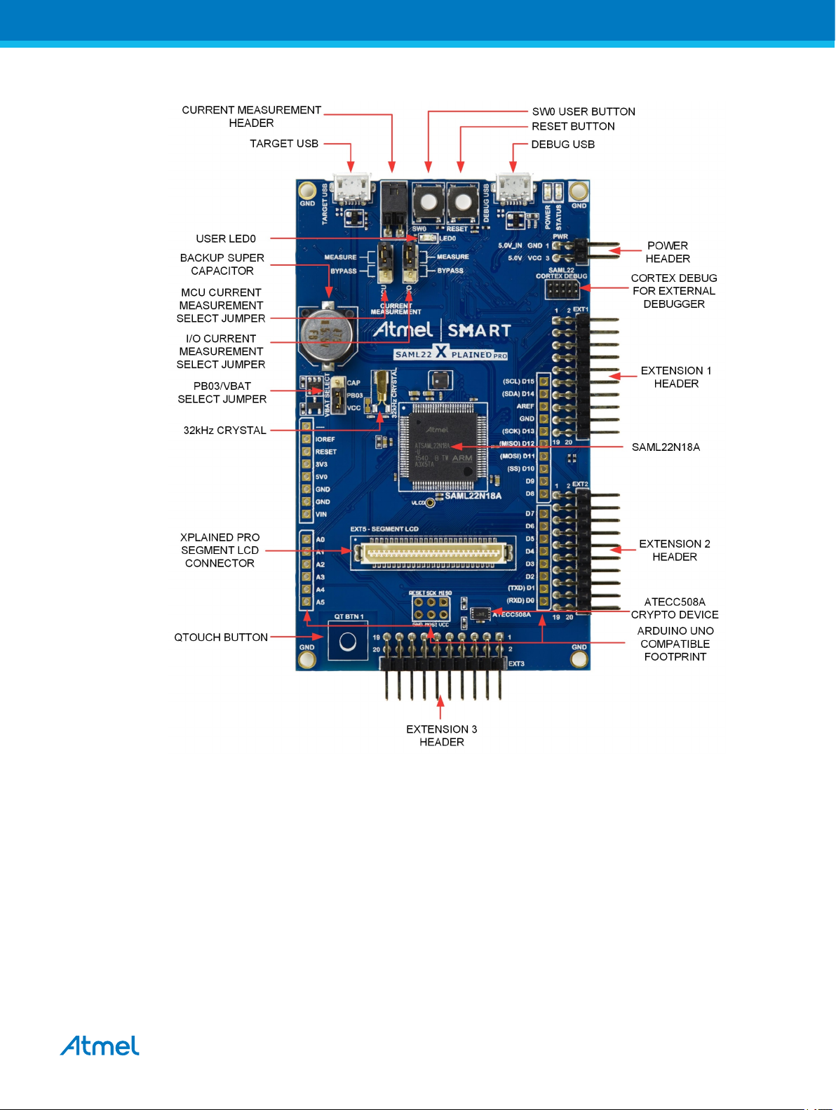
Figure 1-1. SAM L22 Xplained Pro Evaluation Kit Overview
Atmel SAM L22 Xplained Pro [USER GUIDE]
Atmel-42474B-SAM-L22-Xplained-Pro_User Guide-12/2015
5

2. Getting Started
2.1. Xplained Pro Quick Start
Three steps to start exploring the Atmel Xplained Pro platform:
1. Download Atmel Studio.
2. Launch Atmel Studio.
3. Connect a USB cable (Standard-A to Micro-B or Micro-AB) between the PC and the DEBUG USB
port on the kit.
When the Xplained Pro MCU kit is connected to your computer for the first time, the operating system will
perform a driver software installation. The driver file supports both 32- and 64-bit versions of Microsoft
Windows® XP, Windows Vista®, Windows 7, and Windows 8.
Once the Xplained Pro MCU board is powered the green power LED will be lit and Atmel Studio will auto
detect which Xplained Pro MCU- and extension board(s) are connected. Atmel Studio will present
relevant information like datasheets and kit documentation. The kit landing page in Atmel Studio also has
the option to launch Atmel Software Framework (ASF) example applications for the kit. The SAM L22
device is programmed and debugged by the on-board Embedded Debugger and therefore no external
programmer or debugger tool is needed.
2.2. Design Documentation and Relevant Links
The following list contains links to the most relevant documents and software for the SAM L22 Xplained
Pro.
• Xplained Pro products - Atmel Xplained Pro is a series of small-sized and easy-to-use evaluation
kits for Atmel microcontrollers and other Atmel products. It consists of a series of low-cost MCU
boards for evaluation and demonstration of features and capabilities of different MCU families.
• Atmel Studio - Free Atmel IDE for development of C/C++ and assembler code for Atmel
microcontrollers.
• Atmel sample store - Atmel sample store where you can order samples of devices.
• EDBG User Guide - User guide containing more information about the on-board Embedded
Debugger.
• IAR Embedded Workbench® for ARM® - This is a commercial C/C++ compiler that is available for
ARM®. There is a 30 day evaluation version as well as a code size limited kick-start version
available from their website. The code size limit is 16KB for devices with M0, M0+, and M1 cores
and 32KB for devices with other cores.
• Atmel QTouch® Library PTC - QTouch Library for Atmel AVR® and ARM®-based microcontrollers.
• Atmel QTouch® Composer - Tool for developing capacitive buttons, sliders, and wheels
applications.
• Atmel Data Visualizer - Atmel Data Visualizer is a program used for processing and visualizing
data. Data Visualizer can receive data from various sources such as the Embedded Debugger Data
Gateway Interface found on Xplained Pro boards and COM ports.
• Segment LCD1 Xplained Pro - Segment LCD1 Xplained Pro is a segment LCD Xplained Pro
extension with 96 segments that uses four COM and 24 SEG signals. An Xplained Pro MCU board
with a Xplained Pro segment LCD connector is required to use the kit.
• Touch Segment LCD1 Xplained Pro - Touch Segment LCD1 Xplained Pro is a segment LCD
Xplained Pro extension with 179 segments that uses eight COM and 24 SEG signals. The LCD has
®
Atmel SAM L22 Xplained Pro [USER GUIDE]
Atmel-42474B-SAM-L22-Xplained-Pro_User Guide-12/2015
6

five built-in mutual capacitance sensors for use with a PTC module. An Xplained Pro MCU board
with a Xplained Pro segment LCD connector is required to use the kit.
• Design Documentation - Package containing CAD source, schematics, BOM, assembly drawings,
3D plots, layer plots etc.
• Hardware Users Guide in PDF format - PDF version of this User Guide.
Atmel SAM L22 Xplained Pro [USER GUIDE]
Atmel-42474B-SAM-L22-Xplained-Pro_User Guide-12/2015
7
3. Xplained Pro
Xplained Pro is an evaluation platform that provides the full Atmel microcontroller experience. The
platform consists of a series of Microcontroller (MCU) boards and extension boards, which are integrated
with Atmel Studio, have Atmel Software Framework (ASF) drivers and demo code, support data
streaming, and more. Xplained Pro MCU boards support a wide range of Xplained Pro extension boards,
which are connected through a set of standardized headers and connectors. Each extension board has
an identification (ID) chip to uniquely identify which boards are connected to an Xplained Pro MCU board.
This information is used to present relevant user guides, application notes, datasheets, and example
code through Atmel Studio.
3.1. Embedded Debugger
The SAM L22 Xplained Pro contains the Atmel Embedded Debugger (EDBG) for on-board debugging.
The EDBG is a composite USB device of three interfaces; a debugger, Virtual COM Port, and a Data
Gateway Interface (DGI).
Together with Atmel Studio, the EDBG debugger interface can program and debug the ATSAML22N18A.
On SAM L22 Xplained Pro, the SWD interface is connected between the EDBG and the
ATSAML22N18A.
The Virtual COM Port is connected to a UART on the ATSAML22N18A and provides an easy way to
communicate with the target application through terminal software. It offers variable baud rate, parity, and
stop bit settings. Note that the settings on the ATSAML22N18A must match the settings given in the
terminal software.
Info: If not set automatically, data terminal ready (DTR) must be set in the terminal software.
The DGI consists of several physical interfaces for communication with the host computer.
Communication over the interfaces is bidirectional. It can be used to send events and values from the
ATSAML22N18A or as a generic printf-style data channel. Traffic over the interfaces can be timestamped
on the EDBG for more accurate tracing of events. Note that timestamping imposes an overhead that
reduces maximal throughput. Atmel Data Visualizer is used to send and receive data through DGI.
The EDBG controls two LEDs on SAM L22 Xplained Pro; a power LED and a status LED. The table
below shows how the LEDs are controlled in different operation modes.
Table 3-1. EDBG LED Control
Operation mode Power LED Status LED
Normal operation Power LED is lit when power is
applied to the board.
Bootloader mode (idle) The power LED and the status LED blinks simultaneously.
Bootloader mode (firmware
upgrade)
The power LED and the status LED blinks in an alternating pattern.
Activity indicator, LED flashes
when any communication
happens to the EDBG.
For further documentation on the EDBG, see the EDBG User Guide.
Atmel SAM L22 Xplained Pro [USER GUIDE]
Atmel-42474B-SAM-L22-Xplained-Pro_User Guide-12/2015
8
3.2. Xplained Pro Analog Module (XAM)
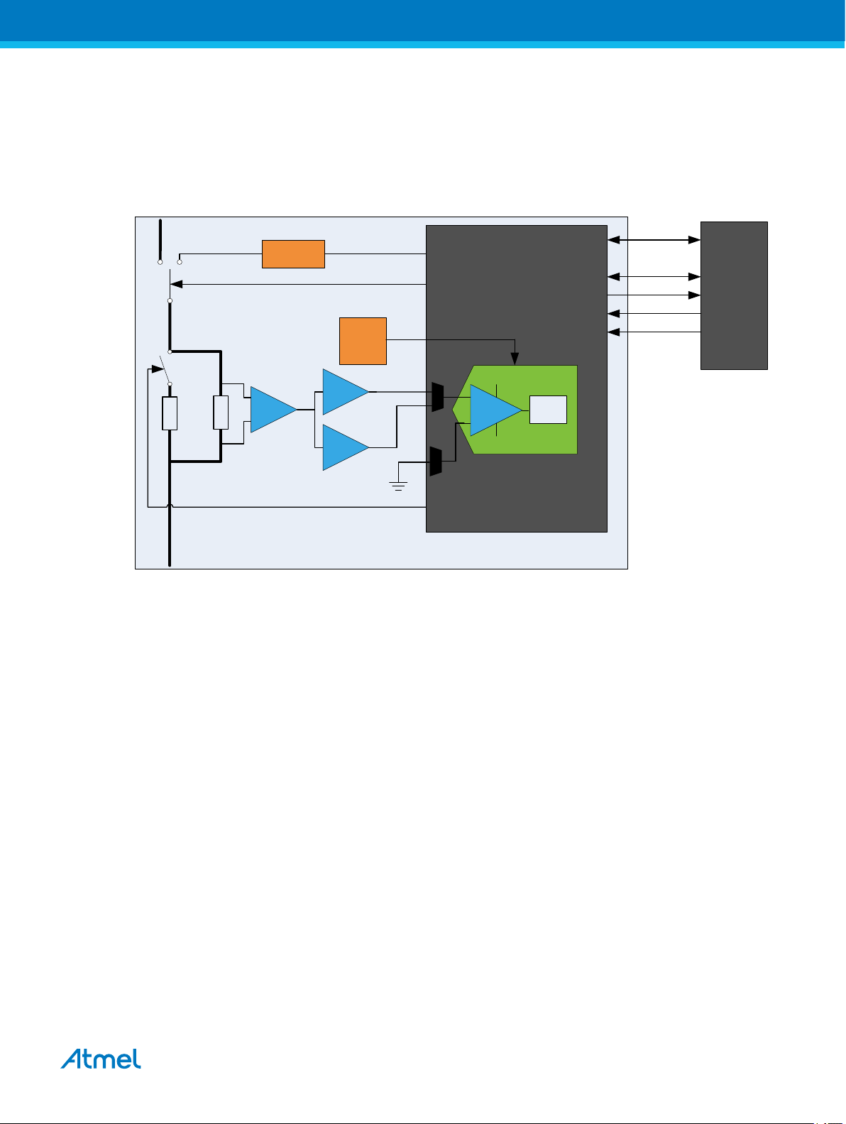
3.2.1. Overview
The Xplained Pro Analog Module (XAM) extends the embedded debugger with high dynamic range
current measurement. This enables power profiling of the target system.
Current output
Range selection
Current input
Calibration ON/OFF
100 mOhm
100 Ohm
Xplained Pro Analog Module (XAM)
The XAM consists of:
• Calibration circuitry
• Voltage reference
• Analog frontend
– Shunt resistors with a range selection switch
– Pre-amplifier
– Two active filters with gain
• Control MCU
– Analog to digital converter
– Signal processing
– Control/communication interface to the EDBG
Calibration
circuitry
Pre-amplifier
20x
20x
voltage
reference
2.7V
2x
16x
Active filter with
gain
GPIO(s)
GPIO
AREF
ADC0
ADC1
GND
GPIO
Control MCU
S&H
ADC
Sync GPIO
I2C
SPI
Clock sync
SWD
EDBG
The current measurement frontend is a high side shunt measurement with a pre-amplifier and a second
active filter stage with gain. The wide dynamic range is achieved by four measurement ranges which are
defined by two shunts and the two parallel second stage active filters with gain.
3.2.2. EDBG Interface
The Xplained Pro Analog Module (XAM) is connected to the EDBG with the following interfaces:
• I2C: This is used to control and configure the XAM
• SPI: Current measurement data is streamed to the EDBG via this interface. This is a one-way data
transfer channel from the XAM to the EDBG
Atmel SAM L22 Xplained Pro [USER GUIDE]
Atmel-42474B-SAM-L22-Xplained-Pro_User Guide-12/2015
9
• SWD: The MCU in the XAM is programmed via SWD from the EDBG
• GPIO: At least one GPIO that is connected to the EDBG from the target MCU is also connected to
the current measurement unit to enable the user to sync current measurements with his application
• Clock sync: Synchronization signal to synchronize ADC measurements with EDBG
• Reference clock: Reference clock for the XAM
3.2.3. Sample Rate
The raw sampling rate of the Xplained Pro analog module (XAM) is up to 250kHz and with the default
averaging configuration (average of 16 samples) the actual output of the XAM is 16.67kSPS (note that
the XAM output sample rate is not an integer fraction of the raw sampling).
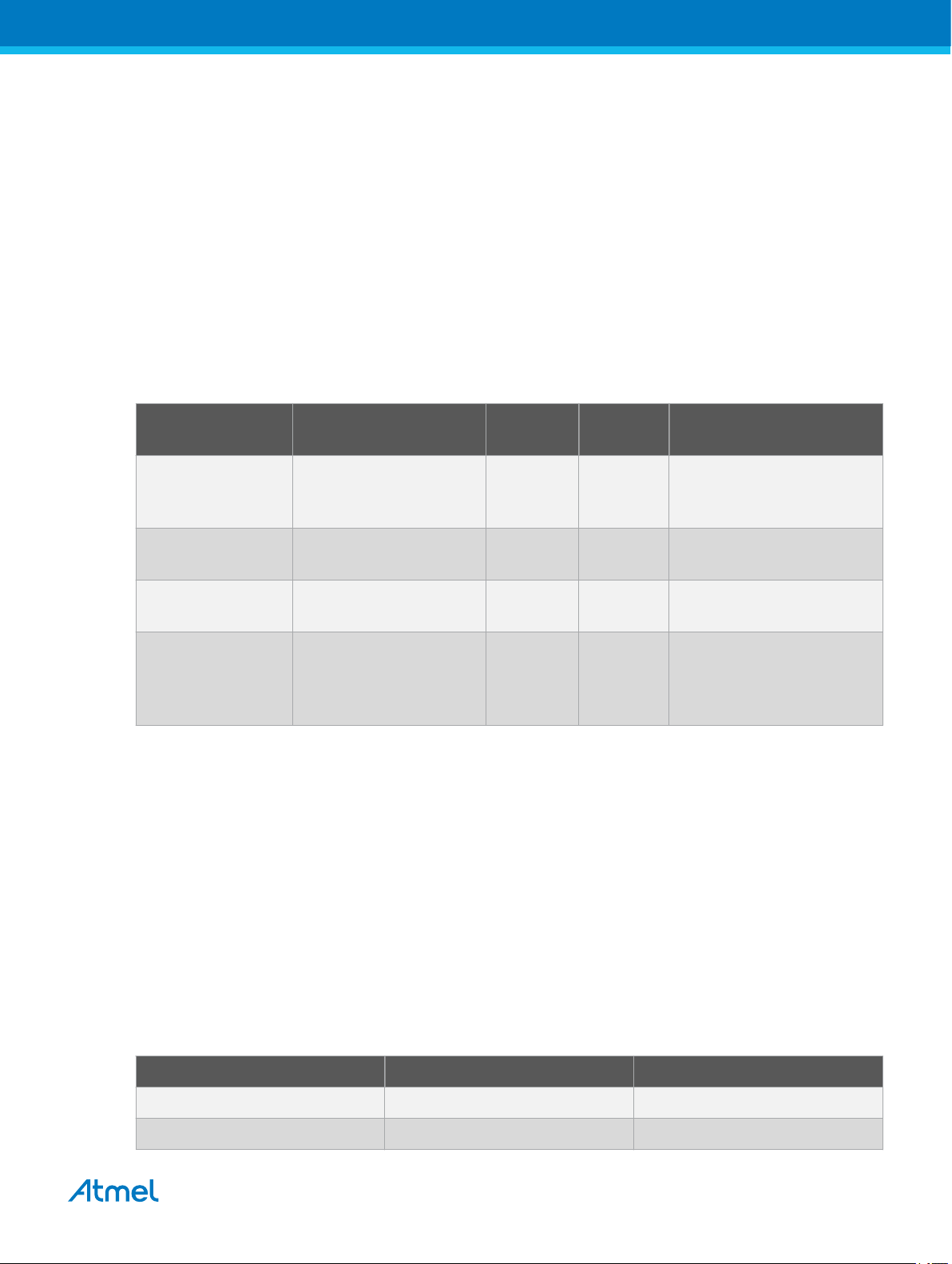
3.2.4. Measurement Ranges and Accuracy
The Xplained Pro analog module has four measurement ranges. These are defined by two shunt resistors
and two gain stages.
Measurement
Hardware Resolution Accuracy Comments
range
Range 1 Low current shunt and
high gain stage
Range 2 Low current shunt and
low gain stage
Range 3 High current shunt and
high gain stage
Range 4 High current shunt and
low gain stage
The ranges are switched automatically by the XAM to achieve best measurement results and the
currently active range is visualized in the Atmel Data Visualizer frontend tool. The maximum voltage drop
over the shunt resistor is 100mV and the XAM will switch the range automatically before this limit is
reached.
3.3. Hardware Identification System
All Xplained Pro compatible extension boards have an Atmel ATSHA204 CryptoAuthentication™ chip
mounted. This chip contains information that identifies the extension with its name and some extra data.
When an Xplained Pro extension is connected to an Xplained Pro MCU board the information is read and
sent to Atmel Studio. The Atmel Kits extension, installed with Atmel Studio, will give relevant information,
code examples, and links to relevant documents. The table below shows the data fields stored in the ID
chip with example content.
20nA 1 LSB ±1% Below 1μA the error will
increase. Typical error for
300nA is 1 LSB ± 10%
150nA 1 LSB ±1%
10μA 1 LSB ±1%
100μA 1 LSB ±1% Above 100mA the error will
increase to 1 LSB ±5% at
400mA. Maximum current is
400mA
Table 3-2. Xplained Pro ID Chip Content
Data field Data type Example content
Manufacturer ASCII string Atmel'\0'
Product Name ASCII string Segment LCD1 Xplained Pro'\0'
Atmel SAM L22 Xplained Pro [USER GUIDE]
Atmel-42474B-SAM-L22-Xplained-Pro_User Guide-12/2015
10

Data field Data type Example content
Product Revision ASCII string 02'\0'
Product Serial Number ASCII string 1774020200000010’\0’
Minimum Voltage [mV] uint16_t 3000
Maximum Voltage [mV] uint16_t 3600
Maximum Current [mA] uint16_t 30
3.4. Power Sources
The SAM L22 Xplained Pro kit can be powered by several power sources as listed in the table below.
Table 3-3. Power Sources for SAM L22 Xplained Pro
Power input Voltage requirements Current requirements Connector marking
External power 5V ±2% (±100mV) for
USB host operation.
4.3V to 5.5V if USB host
operation is not
required.
Recommended
minimum is 1A to be
able to provide enough
current for connected
USB devices and the
PWR
board itself.
Recommended
maximum is 2A due to
the input protection
maximum current
specification.
Embedded debugger
USB
Target USB 4.4V to 5.25V (according
4.4V to 5.25V (according
to USB spec.)
to USB spec.)
500mA (according to
USB spec.)
500mA (according to
USB spec.)
DEBUG USB
TARGET USB
The kit will automatically detect which power sources are available and choose which one to use
according to the following priority:
1. External power.
2. Embedded Debugger USB.
3. Target USB.
Info: External power is required when 500mA from a USB connector is not enough to power
the board with possible extension boards. A connected USB device in a USB host application
might easily exceed this limit.
Atmel SAM L22 Xplained Pro [USER GUIDE]
Atmel-42474B-SAM-L22-Xplained-Pro_User Guide-12/2015
11
3.5. Xplained Pro Headers and Connectors
3.5.1. Xplained Pro Standard Extension Header
All Xplained Pro kits have one or more dual row, 20-pin, 100mil extension header. Xplained Pro MCU
boards have male headers, while Xplained Pro extensions have their female counterparts. Note that all
pins are not always connected. All connected pins follow the defined pin-out description in the table
below.
The extension headers can be used to connect a variety of Xplained Pro extensions to Xplained Pro MCU
boards or to access the pins of the target MCU on Xplained Pro MCU boards directly.
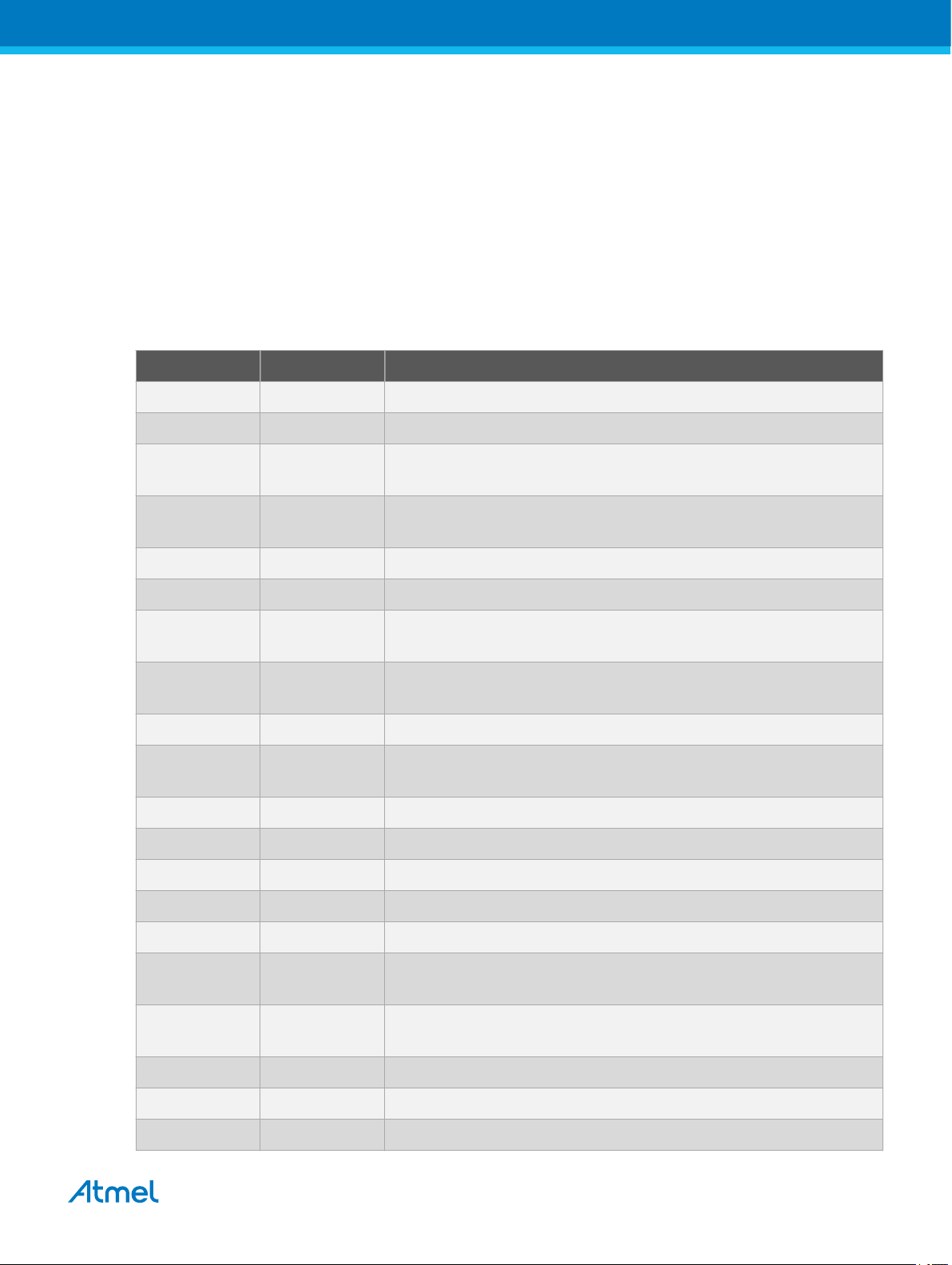
Table 3-4. Xplained Pro Standard Extension Header
Pin number Name Description
1 ID Communication line to the ID chip on an extension board
2 GND Ground
3 ADC(+) Analog to digital converter, alternatively positive part of differential
ADC
4 ADC(-) Analog to digital converter, alternatively negative part of differential
ADC
5 GPIO1 General purpose I/O
6 GPIO2 General purpose I/O
7 PWM(+) Pulse width modulation, alternatively positive part of differential
PWM
8 PWM(-) Pulse width modulation, alternatively negative part of differential
PWM
9 IRQ/GPIO Interrupt request line and/or general purpose I/O
10 SPI_SS_B/
Slave select for SPI and/or general purpose I/O
GPIO
11 I2C_SDA Data line for I2C interface. Always implemented, bus type.
12 I2C_SCL Clock line for I2C interface. Always implemented, bus type.
13 UART_RX Receiver line of target device UART
14 UART_TX Transmitter line of target device UART
15 SPI_SS_A Slave select for SPI. Should preferably be unique.
16 SPI_MOSI Master out slave in line of serial peripheral interface. Always
implemented, bus type.
17 SPI_MISO Master in slave out line of serial peripheral interface. Always
implemented, bus type.
18 SPI_SCK Clock for serial peripheral interface. Always implemented, bus type.
19 GND Ground
20 VCC Power for extension board
Atmel SAM L22 Xplained Pro [USER GUIDE]
Atmel-42474B-SAM-L22-Xplained-Pro_User Guide-12/2015
12
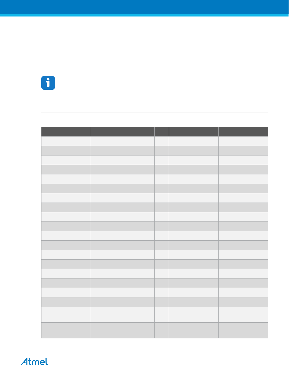
3.5.2. Xplained Pro Segment LCD Connector
Xplained Pro MCU boards that have a microcontroller, which supports segment LCDs, can implement a
51-pin segment LCD extension connector. This connector is implemented with HIROSE DF-9 series.
Xplained Pro MCU boards use the male version DF9-51P-1V(69) and Xplained Pro extension boards use
the female counterpart DF9-51S-1V(69). The connector has a standardized pin-out as shown in the table
below.
Info:
All pins are not connected on all Xplained Pro MCU boards, it depends on how many segments
and common terminals the target MCU supports.
Pin 37, 38, 39, 40, 41, and 42 can alternatively be used for QTouch signals. When they are
used for touch they should not be used for display segments.
Table 3-5. Xplained Pro Segment LCD Connector
Description Function Pin Pin Function Description
Common terminal 3 COM3 1 2 COM2 Common terminal 2
Common terminal 1 COM1 3 4 COM0 Common terminal 0
Segment 0 SEG0 5 6 SEG1 Segment 1
Segment 2 SEG2 7 8 SEG3 Segment 3
Segment 4 SEG4 9 10 SEG5 Segment 5
Segment 6 SEG6 11 12 SEG7 Segment 7
Segment 8 SEG8 13 14 SEG9 Segment 9
Segment 10 SEG10 15 16 SEG11 Segment 11
Segment 12 SEG12 17 18 SEG13 Segment 13
Segment 14 SEG14 19 20 SEG15 Segment 15
Segment 16 SEG16 21 22 SEG17 Segment 17
Segment 18 SEG18 23 24 SEG19 Segment 19
Segment 20 SEG20 25 26 SEG21 Segment 21
Segment 22 SEG22 27 28 SEG23 Segment 23
Segment 24 SEG24 29 30 SEG25 Segment 25
Segment 26 SEG26 31 32 SEG27 Segment 27
Segment 28 SEG28 33 34 SEG29 Segment 29
Segment 30 SEG30 35 36 SEG31 Segment 31
Segment 32 /
QTouch X-line 2
SEG32 / QT_X2 37 38 SEG33 / QT_Y2 Segment 33 /
QTouch Y-line 2
Segment 34 /
QTouch X-line 1
SEG34 / QT_X1 39 40 SEG35 / QT_Y1 Segment 35 /
QTouch Y-line 1
Atmel SAM L22 Xplained Pro [USER GUIDE]
Atmel-42474B-SAM-L22-Xplained-Pro_User Guide-12/2015
13
Description Function Pin Pin Function Description
Segment 36 /
SEG36 / QT_X0 41 42 SEG37 / QT_Y0 Segment 37 /
QTouch X-line 0
Common terminal 4 COM4 43 44 COM5 Common terminal 5
Common terminal 6 COM6 45 46 COM7 Common terminal 6
Backlight anode Backlight V+ 47 48 Backlight V- Backlight cathode
Backlight control Backlight CTRL 49 50 ID Xplained Pro ID
Ground GND 51
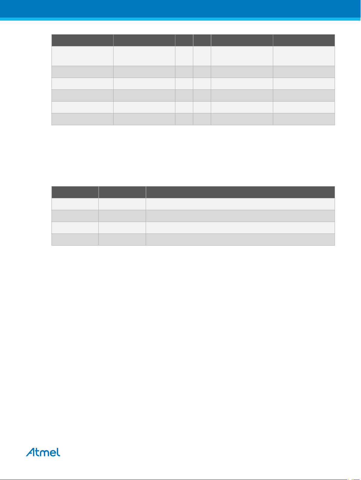
3.5.3. Xplained Pro Power Header
The power header can be used to connect external power to the SAM L22 Xplained Pro kit. The kit will
automatically detect and switch to any external power if supplied. The power header can also be used as
supply for external peripherals or extension boards. Care must be taken not to exceed the total current
limitation of the on-board regulator when using the 3.3V pin.
Table 3-6. Xplained Pro Power Header
Pin number Pin name Description
1 VEXT_P5V0 External 5V input
2 GND Ground
3 VCC_P5V0 Unregulated 5V (output, derived from one of the input sources)
QTouch Y-line 0
4 VCC_P3V3 Regulated 3.3V (output, used as main power supply for the kit)
Atmel SAM L22 Xplained Pro [USER GUIDE]
Atmel-42474B-SAM-L22-Xplained-Pro_User Guide-12/2015
14
4. Hardware User Guide
VCC_P5V0
EDBG & XAM
SAML22N18
Regulator 3.3V
Power source
Power switch
Power converter
Power consumer
VCC_P3V3
Peripherals
Power
Measurement
Select
Auto mux disable
External 5V
input
EDBG USB
Target USB
Auto mux with
current limit
Regulator 3.3V
Jumper
VCC_MCU
VCC_TARGET
Supercap
Select
VBAT
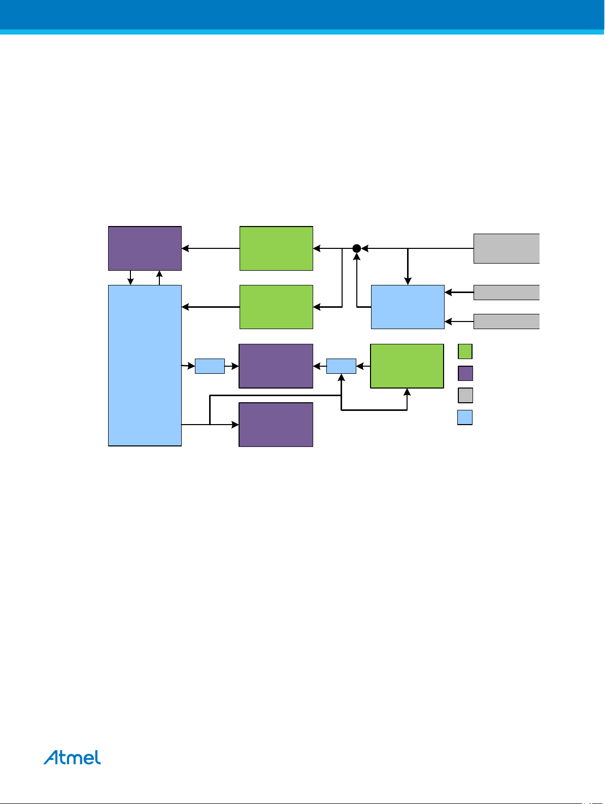
4.1. Power Distribution
SAM L22 Xplained Pro has three power sources; EDBG USB, Target USB, and/or external 5.0V. The kit
will automatically select a source to draw power from. The kit has two on-board 3.3V voltage regulators,
one for the EDBG and XAM and one for the ATSAML22N18A and other peripherals.
An on board super capacitor (47mF) is charged to 3.3V from the target 3.3V net. The super capacitor is
connected to PB03 (VBAT) through a selection header and is intended for backup use in sleep modes.
Figure 4-1. Power Supply Block Diagram
4.2. Connectors
Related Links
Power Sources on page 11
The following sections describes the implementation of the relevant connectors and headers on SAM L22
Xplained Pro and their connection to the ATSAML22N18A. The tables of connections in the sections also
describes which signals are shared between the headers and on-board functionality. The figure below
shows all available connectors and jumpers on SAM L22 Xplained Pro.
Atmel SAM L22 Xplained Pro [USER GUIDE]
Atmel-42474B-SAM-L22-Xplained-Pro_User Guide-12/2015
15
 Loading...