

Page 1

Atme l-42094C-QTouch -Schematic-and-Layout-Checklist-ApplicationNote_072014
APPLICATION NOTE
AT02259: QTouch Schematic and Layout Checklist
Atmel QTouch
Introduction
Designing a capacitive touch interface is an involved process that requires myriad
factors to be considered. These interfaces frequently need to co-exist with other
complex systems, which may affect its performance.
Since there are several considerations to be made while designing Atmel
QTouch
design. The purpose of this document is to provide a checklist that can be used to
review the schematic and PCB layout of these designs. This includes separate
checklists for designs using Atmel QTouch, QTouchADC and QMatrix. This
document only highlights the most important aspects and should not be
considered as a substitute for QTAN0079 Buttons, Sliders and Wheels – Sensor
Design Guide.
®
solutions it is important to know these for overall improvement of the
®
Features
• Checklist for reviewing Atmel QTouch schematics and PCB layouts
Page 2

2
1 Abbreviations and Definitions
The following is a list of terms, which will be used throughout the document.
• Acquisition: A single capacitive measurement process
• Atmel QTouch Library: The set of libraries for the touch sensing technologies offered by Atmel (QTouch,
QTouchADC, and QMatrix)
®
• AVR
• Button: It is a zero dimensional sensor used to implement On/Off digital sensors, and is composed of a
• Channel: A channel is a logical group of pins used to perform the touch acquisition measurement. It can be
• Charge Cycle Period: It is the width of the charging pulse applied to the channel sampling capacitor
• Charge Share Delay: It is the duration when charge is shared between Cs and Cs in QTouchADC
• Ct: The capacitance caused by a finger touch over the Sense Electrode
• Cx: The self-capacitance or mutual-capacitance of the Sense Electrode
• Dwell Cycle: In a QMatrix acquisition method, the duration in which charge coupled from X to Y is
• Port Pair: A combination of SNS port and SNSK port to which sensors are connected in QTouch
• QMatrix: A type of capacitive touch sensing technology that uses the mutual capacitance between two
• QTouch: A type of capacitive touch sensing technology that uses the self capacitance of an electrode
• QTouchADC: A type of capacitive touch sensing technology that uses the self capacitance of an electrode
• Rs: Series resistor on the sense line. This should be in the charging path of Cs
• Sense Component: The set of components connected to the MCU, which are used to perform a touch
• Sense Electrode: Electrodes are typically areas of copper on a printed circuit board. An electrode or a pair
• Sense Line: Any track that connects the Sense Electrode to Sense Components
• Sensor: A channel or group of channels used to form a touch sensor. The three types of sensors are
• Slider: It is a one dimensional sensor used to implement linear position sensors. A group of channels
• SNS Pin: ‘Sense’ pin connected to the sampling capacitor (Cs) in QTouch technology
• SNSK Pin: ‘Sense Key’ pin connected to the electrode through a series resistor (Rs) in QTouch technology
• Wheel: It is a one dimensional sensor used to implement angular position controls. A QTouch Wheel is
• X Line: The Sense Line connected to the X Electrode in QMatrix Technology
• Y Line: The Sense Line connected to the Y Electrode used in QMatrix Technology
• Intra-Port: A configuration for QTouch acquisition method libraries, when the sensor SNS and SNSK pins
• Inter-Port: A configuration for QTouch acquisition method libraries, when the sensor SNS and SNSK pins
: Refers to a device in the Atmel tinyAVR®, megaAVR®, XMEGA®, and UC3 microcontroller (MCU)
family
single channel. It is also known as a Key
composed of a single pin (QTouchADC), a pair of pins (QTouch) or a matrix of pins (QMatrix)
captured
technology. The SNS and SNSK ports used in a port pair can be located in the same AVR Port (eight pins
for four sensors), or they may be on two different AVR Ports (8+8 pins for eight sensors)
electrodes. Each channel has a drive electrode (X Electrode) and a receive electrode (Y Electrode)
connected to a single pin (ADC input)
measurement
of electrodes used to detect a finger touch
Buttons, Sliders, and Wheels
forms a Slider, which is used to detect the linear position of touch. A QTouch Slider is composed of three
channels. A QMatrix Slider can be composed of three to eight channels
composed of three channels. A QMatrix Wheel can be composed of three to eight channels. It is also know
as a Rotor
are available on the same port
are available on distinct ports
QTouch Schematic and Layout Checklist [APPLICATION NOTE]
Atme l-42094C-QTouch -Schematic-and-Layout-Checklist-ApplicationNote_072014
Page 3

3
2 Schematic Review
This chapter consists of the checklists used for reviewing the schematics of Atmel QTouch, QTouchADC and
QMatrix implementations. There are sections corresponding to each individual technology. Section 2.4 General
is applicable to all technologies.
2.1 Atmel QTouch
This section consists of the checklist for reviewing a QTouch schematic.
• Connect SNSK to the sensor electrode
The sense electrode should be connected to the SNSK pin and not to the SNS pin. If the electrode is connected
incorrectly, in some cases it may appear to work. This can happen due to parasitic capacitances providing an
alternate path for charge transfer to occur. But the channel will have very poor sensitivity and will be very
sensitive to temperature and humidity. Therefore it is important to verify the connections before attempting to
improve sensitivity.
Figure 2-1. Typical QTouch Circuit
• Rs = 1kΩ to 10kΩ
The value of Rs should typically be within the range of 1kΩ to 10kΩ. If Rs is increased the value of Charge Cycle
Period will need to be increased appropriately to ensure complete charging of Cx.
Increase Rs in steps up to 100kΩ to improve performance in noisy environments. In extreme
cases higher values of Rs, going up to 1MΩ may be required.
QTouch Schematic and Layout Checklist [APPLICATION NOTE]
Atme l-42094C-QTouch -Schematic-and-Layout-Checklist-ApplicationNote_072014
Page 4
4
• Cs = 1nF to 47nF
The value of Cs should typically be within the range of 1nF to 47nF (not pF or µF). It is best to start with a nominal
value of 10nF and fix the Cs values after tuning is done on a prototype.
Cs can be larger than 47nF for proximity sensors.
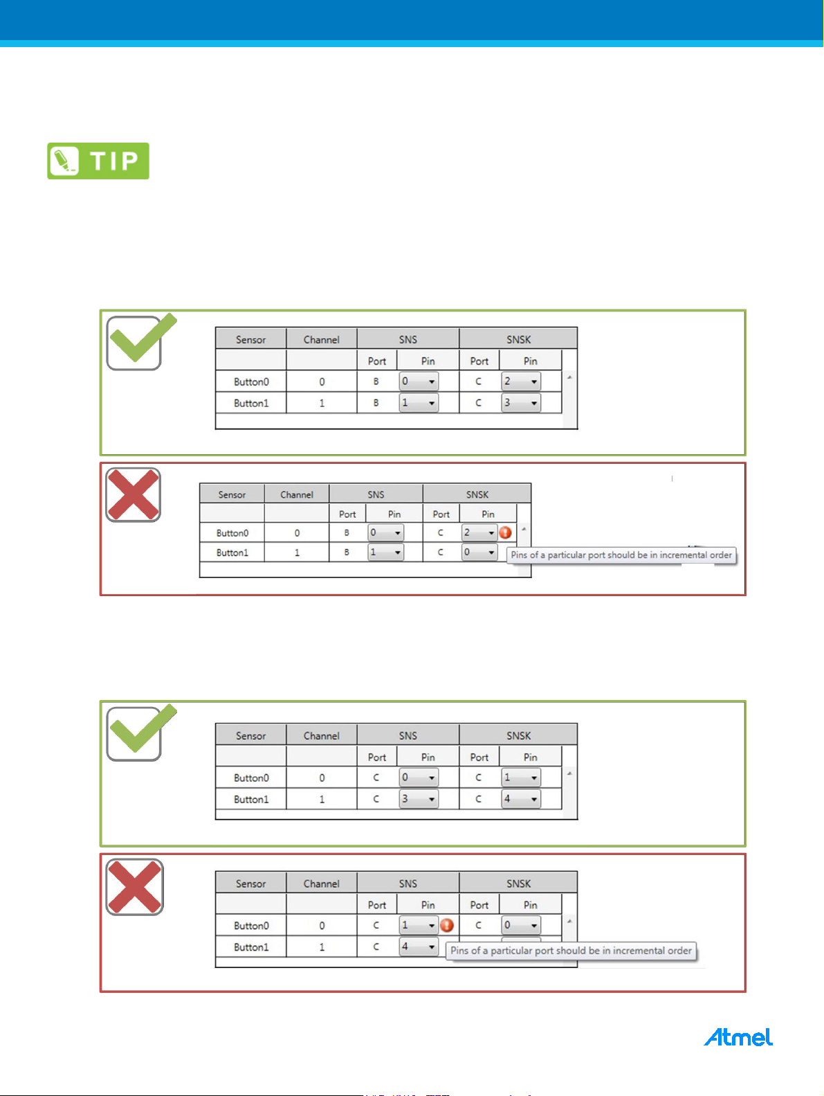
• Sense pin selection for Inter-Port / Intra-Port
In Inter-Port connection, sense pins (SNS/SNSK) selected should be in incremental order as channel number of
the sensor.
Figure 2-2. Pin Selection for Inter-Port Design
In Intra-Port connection, sense pins selected should be in incremental order as channel number of the sensor.
Always SNS pin should be the lower numbered pin, in a channel.
Figure 2-3. Pin Selection for Intra-Port Design
QTouch Schematic and Layout Checklist [APPLICATION NOTE]
Atme l-42094C-QTouch -Schematic-and-Layout-Checklist-ApplicationNote_072014
Page 5

5
• Slider/Wheel uses only three channels
A QTouch Slider/Wheel always uses only three channels. It is important to use channels with similar sensitivity.
Using mismatched channels with significantly different sensitivities will lead to an unbalanced Slider/Wheel.
Always split third channel (highest numbered channel) in a QTouch Slider.
• Sense pins selected for Slider/Wheel are not unbalanced
Ensure that the sense pins selected for Slider/Wheel are not unbalanced. If loaded pins are combined with
regular GPIOs, the linearity of the Slider/Wheel will be poor.
• Multiplexing sense lines with Programming lines
SNSK sense line can be multiplexed with ISP lines. It is better to not use SNS lines for multiplexing with
programming lines, as the extended track lengths might cause loading and interference effects.
For lesser pin count devices which mandate multiplexing, SNS lines can be used with shorter trace length
possible.
Do not use same channel sense (SNS and SNSK) lines for multiplexing programming lines.
Since the sampling capacitor (Cs) used across would affect device programming.
2.2 Atmel QTouchADC
This section consists of the checklist for reviewing a QTouchADC schematic.
• Sense Electrode is connected to an ADC input pin
The QTouchADC acquisition method uses the ADC module. Hence the sense channel needs to be configured on
a port which has the ADC input pins.
QTouch Schematic and Layout Checklist [APPLICATION NOTE]
Atme l-42094C-QTouch -Schematic-and-Layout-Checklist-ApplicationNote_072014
Page 6

6
Rs1
PA0 (ADC0)
PA1(ADC1)
Rs2
Rs3
PA2 (ADC2)
PA3 (ADC3)
Rs4
Key 0
Key 1
Key 2
Key 3
Figure 2-4. Typical QTouchADC Circuit
• Rs = 1kΩ to 10kΩ
The value of Rs should typically be within the range of 1kΩ to 10kΩ. If Rs is increased the value of Charge Share
Delay (CSD) will need to be increased appropriately to ensure complete charging of Cx.
Increase Rs in steps up to 100kΩ to improve performance in noisy environments. In extreme
2.3 Atmel QMatrix
This section consists of the checklist for reviewing a QMatrix schematic.
• For QMatrix designs VCC is 4.5V or below
The supply voltage for QMatrix designs should be kept at 4.5V or below even if the device is capable of operating
above 4.5V. This is required for reliable operation of the QMatrix sensors.
• Pin selection is appropriate
X pins, YA pins and SMP pin are configured on GPIOs. YB pins are configured on the ADC port. The AIN0 pin is
fixed for the device and can be easily identified from the QTouch Library Selection Guide and the device
datasheet. The AIN0 pin needs to be grounded.
cases higher values of Rs, going up to 1MΩ may be required.
The AIN0 pin is not user configurable.
QTouch Schematic and Layout Checklist [APPLICATION NOTE]
Atme l-42094C-QTouch -Schematic-and-Layout-Checklist-ApplicationNote_072014
Page 7

7
Figure 2-5. Typical QMatrix Circuit
• Cs = 1nF to 47nF
The value of Cs should typically be within the range of 1nF to 47nF. In QMatrix acquisition technique a dual-slope
approach is used to detect a touch. Hence Cs does not affect sensitivity. But if extreme values are used it can
hinder the acquisition process. If the value of Cs is too low it is possible that the reverse charge build-up (VCS)
gets saturated. If it is set too high the VCS may be too small.
Typical value of Cs is 4.7nF. Increase it to 10nF if saturated.
• Rx/Ry = 1kΩ to 10kΩ
The value of Rx/Ry should typically be within the range of 1kΩ to 10kΩ. If Rx/Ry is increased the value of Dwell
Time will need to be increased appropriately to ensure complete charging of Cx.
Increase Ry in steps up to 100kΩ to improve performance in noisy environments. In extreme
cases higher values of Ry, going up to 1MΩ may be required.
• Rsmp = 220kΩ to 1MΩ
Rsmp can be any value within the range of 220kΩ to 1MΩ. This value is used to tune the sensitivity of the
channels sharing the corresponding Y-line.
Typically a 470kΩ resistor is used.
QTouch Schematic and Layout Checklist [APPLICATION NOTE]
Atme l-42094C-QTouch -Schematic-and-Layout-Checklist-ApplicationNote_072014
Page 8

8
• Do not use AIN1 pin for PWM generation
QMatrix method uses Analog comparator for touch measurement and the AIN1 pin is connected to negative
terminal of Analog comparator. So, the switching signals in AIN1 pin would affect touch measurement.
• Using same Port for YA/YB Lines
Prefer using different Port for YA and YB lines, in case of designs that does not have pin count constraints.
• Multiplexing sense lines with Programming lines
X lines can be multiplexed with ISP lines. It is preferable to not share Y lines (both YA and YB) with programming
lines.
For lesser pin count devices which mandate multiplexing, Y lines can be used with shorter trace length possible.
Do not share same channel Y lines (YA and YB) with programming lines.
• Slider/Wheel uses four to eight channels
A QMatrix Slider/Wheel always uses a minimum of four channels. This can be increased up to eight channels for
a bigger Slider/Wheel. It is important to use channels with similar sensitivity. Using mismatched channels with
significantly different sensitivities will lead to an unbalanced Slider/Wheel.
• Slider/Wheel resistive interpolation resistors are in range
Total resistance between channels is 2kΩ to 10kΩ. The resistance between segments will depend on the
number of segments used.
There are no end resistors or split channels for a QMatrix Slider.
Figure 2-6. Resistive Interpolated QMatrix Slider and Wheel
QTouch Schematic and Layout Checklist [APPLICATION NOTE]
Atme l-42094C-QTouch -Schematic-and-Layout-Checklist-ApplicationNote_072014
Page 9

9
2.4 General
This section consists of the general checklist for reviewing a schematic. This is applicable to all implementations.
• Sense pins are not loaded
Ensure that the sense pins are not heavily multiplexed as this can cause increased loading. XTAL/OSC/RESET
pins usually have high parasitic capacitance values and are not suitable. If loaded pins are used, the sensitivity of
the channel will be poor.
• Sampling Capacitor is X7R or better
Stability of the Cs capacitor is important in achieving a consistent and repeatable measurement. A capacitor with
X7R dielectric or better has a low temperature co-efficient and will be more stable.
Quality of series resistor Rs is not critical.
• Dedicated voltage regulator is used
It is recommended to use a dedicated voltage regulator for a QTouch application. If the voltage regulator is
shared with other components it is important to ensure that the power supply is clean.
The ripple on the supply voltage needs to be within ±10mV.
Figure 2-7. Regulated Supply Circuit Configurations (Optional Components are Highlighted in Red)
Typical regulated supply circuit
With other devices
QTouch Schematic and Layout Checklist [APPLICATION NOTE]
Atme l-42094C-QTouch -Schematic-and-Layout-Checklist-ApplicationNote_072014
Page 10

10
For lower cost products
• Any load on GPIO pins does not source or sink more than ~1mA
If there is any load on a discrete out pin of the microcontroller, ensure that the load does not sink or source too
much current directly from chip. This can cause ground bounce which would in turn affect QTouch
measurements. Typically the current should be limited to ~1mA, but this can vary depending on the part and
sensitivity of channels. If required use transistors etc. to lower load current.
• No additional circuitry on sense lines
Placing ESD protection circuitry, MUX, etc are not recommended since they add parasitic capacitance and may
introduce noise. Placing option resistors on the sense lines to connect the pins to different circuitry is acceptable.
But the sensitivity of the channel needs to be re-tuned if options change.
• Nearby LEDs have a bypass capacitor
The changing capacitance from switching LEDs can cause detection instability and stuck-on state in nearby
sensors. This is particularly true if LEDs are pulled down or up to switch on, but are allowed to float when off.
If such LEDs are less than 4mm away from capacitive sensors, they must be bypassed with a capacitor that has
a typical value of 1nF.
Bypass capacitor does not need to be physically close to the LED.
Figure 2-8. Bypass Capacitors on Nearby LEDs
QTouch Schematic and Layout Checklist [APPLICATION NOTE]
Atme l-42094C-QTouch -Schematic-and-Layout-Checklist-ApplicationNote_072014
Page 11

11
• LEDs and sense lines do not share the same port
Avoid placing LEDs on the same port as the sense lines, since switching LEDs can cause the touch
measurement to be noisy. If they are required to be on the same port it is recommended to increase the value of
the LED series resistor to minimize the impact.
• Use multiple grounds in case of isolated sensors
When sensor board is isolated from touch MCU board, prefer using multiple ground pins in the connector for
effective return path.
QTouch Schematic and Layout Checklist [APPLICATION NOTE]
Atme l-42094C-QTouch -Schematic-and-Layout-Checklist-ApplicationNote_072014
Page 12

12
Too big
Cx
Ct
EARTH
EARTH
3 PCB Review
This chapter consists of the checklists used for reviewing the PCB layout of Atmel QTouch, QTouchADC and
QMatrix implementations. There are sections corresponding to each individual technology.
For general PCB design considerations please refer to AVR042: AVR Hardware Design
Considerations.
3.1 QTouch and QTouchADC
This section consists of the checklist for reviewing the PCB layout for both QTouch and QTouchADC designs.
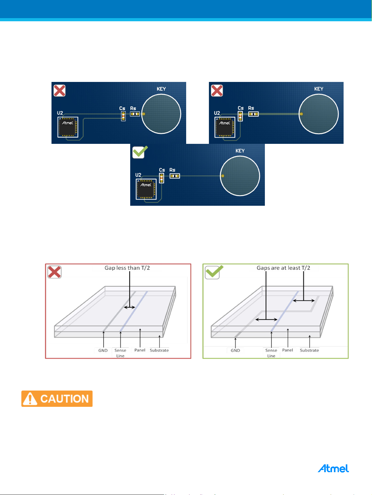
3.1.1 Components
• Sense components are placed close to microcontroller pins
The sense components (Cs and Rs for QTouch; only Rs for QTouchADC) should be placed close to the
microcontroller sense pins. If they are placed too far from the pin, there will be increased noise pick-up from
nearby sources.
3.1.2 Sensors
• Electrode size is slightly larger than a normal finger
It is recommended to have a key size that is slightly larger than the item to be sensed (finger, thumb etc). In
general larger keys are more sensitive, but avoid oversized keys as they may have a proximity effect.
Area of contact from a normal finger is 8mm to 10mm in diameter.
Figure 3-1. Appropriate Sensor Size
• Sense Electrodes are located on the top layer
The sense electrodes should be located on the layer closest to touch in order to maximize the sensitivity.
Do not place the MCU or any other components directly under the Sense
QTouch Schematic and Layout Checklist [APPLICATION NOTE]
Atme l-42094C-QTouch -Schematic-and-Layout-Checklist-ApplicationNote_072014
Electrodes.
Page 13

13
• Spacing between adjacent Sense Electrodes is at least T/2
The separation between keys should be at least half of T (front panel thickness), to prevent cross-coupling and
unintentionally touching a neighbouring key. The probability of an unintentional touch from the palm or
hand-shadow should be minimal.
• LED holes have diameter less than 4mm
LED holes that are too large can lead to poor sensitivity or cause the key to have a dead spot in the middle.
Figure 3-2. Hole for Backlighting LED
3.1.3 Routing
• Sense Lines are routed on the bottom layer
Sense tracks are sensitive to touch and wherever possible they must be routed on the bottom layer to prevent
false keys on the touch surface.
• Spacing between adjacent Sense Lines is at least T/2
If Sense Lines are placed close to each other, it can cause cross-bleed and increase noise on the channels. It will
also load both channels and decrease their sensitivity.
Figure 3-3. Spacing Between Two Sense Lines
QTouch Schematic and Layout Checklist [APPLICATION NOTE]
Atme l-42094C-QTouch -Schematic-and-Layout-Checklist-ApplicationNote_072014
Page 14
14
• Sense Line thickness should be between 0.1mm to 0.5mm
To prevent false detect over electrode traces keep them thin. The Electrodes drive very small loads so minimum
metal trace widths may be used.
Figure 3-4. Typical QTouch Button Layout
• Sense Lines are separated from GND tracks by at least T/2
GND tracks should not be placed near Sense Lines. This will load the Sense Lines and reduce the sensitivity of
the channel. To reduce loading the Sense Lines and GND track should cross at 90° on separate layers.
Figure 3-5. Typical QTouch Button Layout
• Sense Lines are as short as possible
Having long Sense Lines will worsen any loading and interference from nearby tracks and components.
Sense Lines should not be longer than 150mm.
QTouch Schematic and Layout Checklist [APPLICATION NOTE]
Atme l-42094C-QTouch -Schematic-and-Layout-Checklist-ApplicationNote_072014
Page 15
15
• Sense Lines are separated from all other tracks and components by at least T/2
Sense Lines should not be placed near other tracks and components, as this may cause loading and
interference. These will load the Sense Lines and reduce the sensitivity of the channel. Tracks with switching
signals can cause noise in the Sense Lines if they are placed too close.
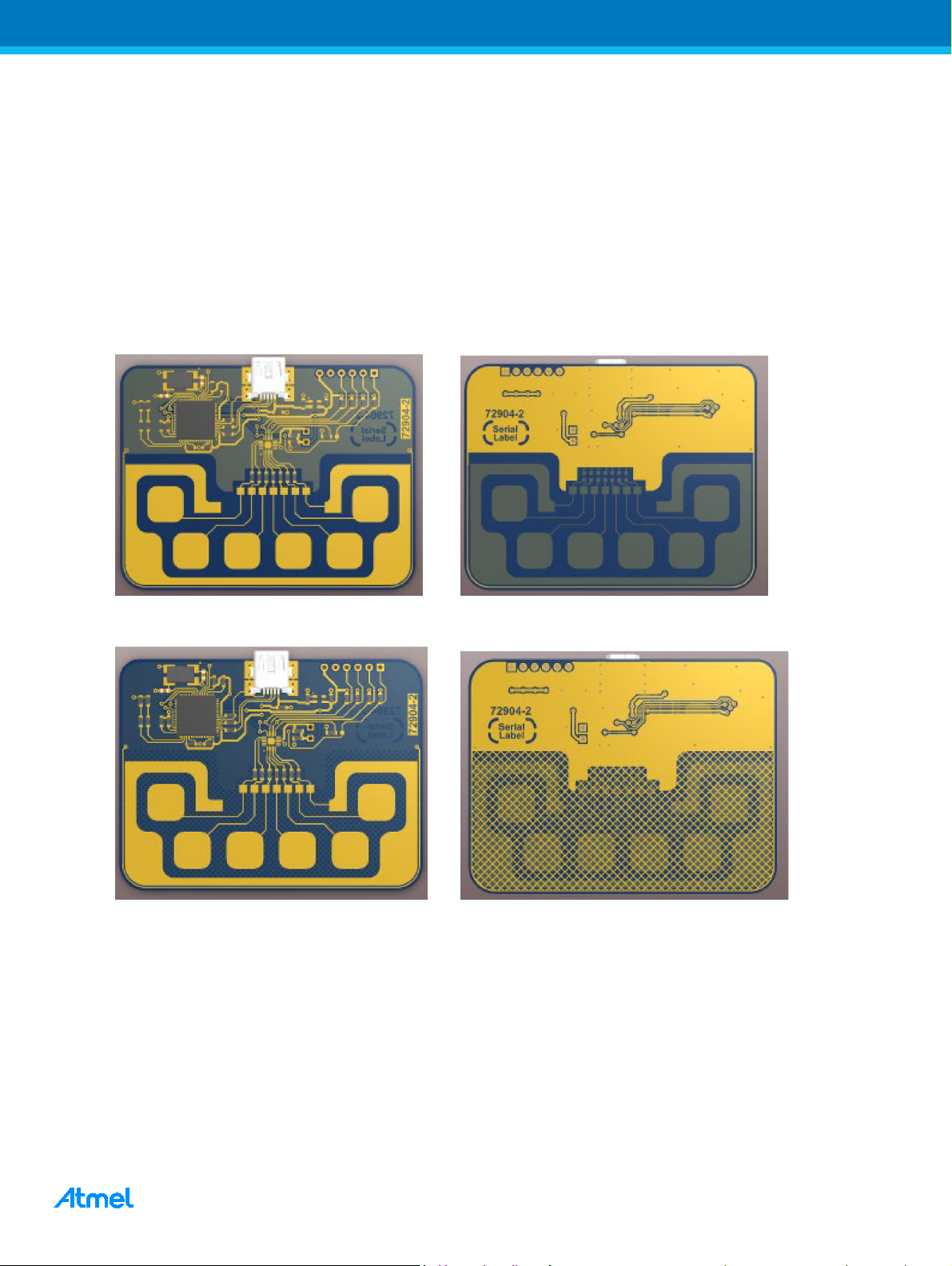
• There is no GND plane behind components, tracks and electrodes
Keep solid Ground Plane or Fill away from the Sensor Signals. If shielding from noise sources is necessary a thin
meshed ground may be used behind electrodes (<40% copper). Meshed ground can also be helpful in increasing
SNR and stability when conducted noise is present.
Figure 3-6. No Ground Flood Under Sense Components, Tracks, and Electrodes
Figure 3-7. Meshed Ground to Provide Shielding from Noise Sources Behind the Board
3.1.4 QTouch Slider or Wheel
The checklist in this section is applicable only to QTouch designs.
• Small Slider/Wheel has a segment size of 6mm to 8mm
Segment size should be comparable to the diameter of a standard finger touch. Segments that are too large will
lead to poor linearity. In case of Wheel the outer arc of the segment should of length 6mm to 8mm. This is
applicable to small spatially interpolated Slider/Wheel which uses simple rectangular or wedge shaped
segments.
QTouch Schematic and Layout Checklist [APPLICATION NOTE]
Atme l-42094C-QTouch -Schematic-and-Layout-Checklist-ApplicationNote_072014
Page 16

16
• For a small spatially interpolated Slider the end segments are half the width of the middle two
segments
The end segments, which are connected to the same channel, need to be narrower to ensure linearity near the
ends of the Slider.
Figure 3-8. Small Spatially Interpolated – Length 21mm to 26mm
• The first and last segments of the Slider are connected to the same channel
This needs to be ensured for both spatially and resistively interpolated QTouch Sliders.
• The track connecting end segments is placed away from the Slider
The track needs to be placed away from the Slider to prevent accidentally touching it while sliding the finger. This
can lead to incorrect position being reported.
• Medium/large spatially interpolated Sliders have segment width of 4mm or less
The segments need to be narrow to ensure that the finger interacts with more than one segment when touching
the slider. The regions between the segments must have interleaving teeth.
Figure 3-9. Medium/Large Spatially Interpolated QTouch Slider – Length 26mm to 60mm
QTouch Schematic and Layout Checklist [APPLICATION NOTE]
Atme l-42094C-QTouch -Schematic-and-Layout-Checklist-ApplicationNote_072014
Page 17

17
To increase the height of the Slider increase the number of interleaving teeth (don’t stretch
the same pattern).
Figure 3-10. Repeat Interleaving Pattern to Add Height to Slider
Figure 3-11. Repeat Interleaving Pattern to Add Height to Slider
• There are no switching traces/components under the Slider/Wheel
These can degrade the SNR and compromise the achievable resolution. This can manifest itself as jitter in the
reported touch co-ordinate and is not desirable.
• There are no ground planes under the Slider/Wheel
Ground planes under the Slider/Wheel will load the sensor and make it less sensitive. Ground planes that
unevenly load some of the channels are worse than all the channels being equally loaded.
Although GND loading decreases sensitivity, it increases SNR and Signal stability which can
be useful in noisy environments.
• Medium/large spatially interpolated Wheels have segment width of 4mm or less
The segments need to be narrow to ensure that the finger interacts with more than one segment when touching
the slider. The regions between the segments must have curved interleaving teeth.
• In a medium/large spatially interpolated Wheel the width of each interleaving ring is 5mm to 8mm
For increasing the diameter of the Wheel increase the number of interleaving rings rather than increasing the
width of the ring.
QTouch Schematic and Layout Checklist [APPLICATION NOTE]
Atme l-42094C-QTouch -Schematic-and-Layout-Checklist-ApplicationNote_072014
Page 18

18
Figure 3-12. Larger Spatially Interpolated QTouch Wheel with an Additional Ring of Interleaving Teeth
3.2 QMatrix
This section consists of the checklist for reviewing the PCB layout for QMatrix designs.
3.2.1 Components
• Sense components are close to the microcontroller
The sense components (Sampling Capacitor Cs, Series Resistor Rx/Ry) should be placed close to the
microcontroller sense pins. The Cs and Rx/Ry components form an RC filter and if they are placed too far from
the pin the filtering effect is diminished.
The Rsmp (sampling resistor) should be placed closer to Y sense pin. It is OK to place the Rsmp resistor further
from SMP pin since it is always driven.
3.2.2 Sensors
• There are no ground planes directly under co-planar Buttons
These will load the sensor and decrease the sensitivity. But the effect is not as dramatic as in the case of QTouch
Sensors.
• Y Electrodes are located on the top layer
The Y electrodes should be located on the layer closest to touch in order to maximize the sensitivity.
• X Electrodes completely surround the Y Electrodes
In QMatrix sensors the field only exists in the gap between the X Electrode and Y Electrode. Surrounding the Y
Electrode with the X Electrode will keep the field contained and the touch sensitive area can be precisely defined.
• The X-Y interdigitation is maximized
Designs that result in very small X-Y inter-digitation should be avoided as such designs result in poor sensitivity.
QTouch Schematic and Layout Checklist [APPLICATION NOTE]
Atme l-42094C-QTouch -Schematic-and-Layout-Checklist-ApplicationNote_072014
Page 19

19
Single Layer Planar Electrode Layout
(the field only extends towards touch)
Large X-Y Separation = Thicker Panel
X
Y
X
T/2
T
Y
X
T
T/2
XY
X
T/2
T
Y
X
T
T/2
Figure 3-13. Typical QMatrix Co-Planar (Single Layer) Button
• Spacing between X and Y Electrodes is at least T/2
The spacing between the X and Y electrode needs to be at least half the front panel thickness. If the front panel
thickness is T then the X-Y gap should be at least T/2. There should be no other tracks running below the X-Y
gap as this can desensitize the key.
In flooded-X designs X-Y separation is determined by the PCB thickness.
Therefore the acceptable front panel thickness is constrained by the thickness
of the PCB used.
Figure 3-14. X-Y Separation and Front Panel Thickness
Double Layer Flooded-X Electrode Layout
Small X-Y separation = Thin Panel
QTouch Schematic and Layout Checklist [APPLICATION NOTE]
Atme l-42094C-QTouch -Schematic-and-Layout-Checklist-ApplicationNote_072014
Page 20

20
• Spacing between X Electrodes is not critical
The X Electrodes are not susceptible to loading. They can be placed with minimal separation without affecting
neighbouring keys. Keys that share the same X Line, the X electrodes can be merged.
Figure 3-15. Keys That Share the Same X Line, the X Electrodes Can be Merged
• In two layer design Y Electrodes are on the top layer (closest to touch)
The Y Electrode should be on the top layer in order to maximize the interaction of the finger with the X-Y electric
field, thus maximizing the sensitivity of the sensor.
X Electrode on the bottom layer can provide shielding from noise sources behind the board.
Figure 3-16. QMatrix Flooded X (Two Layer) Design
3.2.3 Routing
• Y Lines are as thin and short as possible
Having long Sense Lines will worsen any loading and interference from nearby tracks and components. The
thickness of the Y electrode should be kept as low as possible (0.1mm to 0.5mm) to minimize noise pickup when
touched.
The Y Lines should not be longer than 150mm.
• Y Lines are separated from GND tracks by at least T/2
GND tracks should not be placed near Y Lines. This will load the Sense Lines and reduce the sensitivity of the
channel. If absolutely necessary the Y Lines and GND track should cross at 90° on separate layers. Y Lines and
GND tracks running parallel to each other for long distances should absolutely be avoided.
QTouch Schematic and Layout Checklist [APPLICATION NOTE]
Atme l-42094C-QTouch -Schematic-and-Layout-Checklist-ApplicationNote_072014
Page 21

21
YLine
GND
Panel
Substrate
Gap less than T/2
Gaps are at least T/2
YLine
GND
Panel
Substrate
Figure 3-17. Y Line Separation from GND
• Y Lines are separated from all other tracks and components by at least T/2
Y Lines should not be placed near other tracks and components, as this may cause loading and interference.
These will load the Y Lines and reduce the sensitivity of the channel. Tracks with switching signals can cause
noise in the Y Lines if they are placed too close.
X Lines and X Electrodes are not sensitive to loading from ground planes and foreign
tracks/components.
• Y Lines are routed on the bottom layer
Y Lines are sensitive to touch and wherever possible they must be routed on the bottom layer to prevent false
keys on the touch surface.
Figure 3-18. Cross-Section of a Multi-Layer PCB
• Spacing between adjacent Y Lines is at least T/2
If Y Lines are placed close to each other, it can cause cross-bleed and increase noise on the channels. It will also
load both Y Lines and decrease their sensitivity.
QTouch Schematic and Layout Checklist [APPLICATION NOTE]
Atme l-42094C-QTouch -Schematic-and-Layout-Checklist-ApplicationNote_072014
Page 22

22
• X Lines and Y Lines are not routed near each other
The X-lines are not touch sensitive and hence their routing is not as critical. But it is important to ensure that they
are not routed near Y-lines as this may create false keys (Figure 3-19). If the lines need to run together or cross
then extra care needs to be taken to avoid false keys. Some routing suggestions are illustrated in Figure 3-20.
Figure 3-19. X and Y Lines Placed Close to Each Other Can Behave Like a Button
Figure 3-20. Tips for Minimizing Interaction Between X and Y Routing
o
a. 90
crossing
c. X under Ground trace
b. Separating ground trace
d. Y under X
• X Lines and Y Lines Interconnection using Flex cables
When using Flex cables for interconnection of sense lines, group all X lines together and group Y lines together,
and then use a ground trace in between the groups. This avoids formation of stray capacitance across the closely
routed X and Y line.
QTouch Schematic and Layout Checklist [APPLICATION NOTE]
Atme l-42094C-QTouch -Schematic-and-Layout-Checklist-ApplicationNote_072014
Page 23

23
3.2.4 Sliders and Wheels
• There are no ground planes or foreign traces/components under the Slider/Wheel
These can degrade the SNR and compromise the achievable resolution. This can manifest itself as jitter in the
reported touch co-ordinate and is not desirable.
• Slider/Wheel has a segment size of 6mm to 8mm
Segment size should be comparable to the diameter of a standard finger touch. Segments that are too large will
lead to poor linearity. In case of Wheels the outer arc of the segment should be 6mm to 8mm long.
• In single layer Slider/Wheel, isolated X regions are connected using vias
Since the Slider segments are on the same layer, the Y Electrode cuts through the X Electrode. This causes the
X Electrodes to be split. These isolated regions need to be connected on the bottom layer using jumpers or vias.
Figure 3-21. Single Layer Slider/Wheel with X Electrodes Split by the Y Electrode
• In two layer Slider/Wheel the gap between Y Electrode traces is less than 4mm
Gaps that are larger than 4mm can lead to an insensitive region on the Slider/Wheel.
Figure 3-22. Two Layer QMatrix Slider/Wheel
QTouch Schematic and Layout Checklist [APPLICATION NOTE]
Atme l-42094C-QTouch -Schematic-and-Layout-Checklist-ApplicationNote_072014
Page 24

24
3.3 General
This section consists of the general checklist for reviewing a PCB Layout.
• Front Panel Material and Coating
The coating material used over dielectric front panel that covers touch sensor should not be conductive.
Conductive paint used over front panel causes sensitivity to spread across the panel and could cause abnormal
touch operation.
Refer to “QTAN0079 Buttons, Sliders and Wheels – Sensor Design Guide” for more details
• Floating metal nearby touch sensors to be grounded
Floating conductive items nearby touch sensors would re-radiate the sensor’s electric field and might cause false
detections. It is essential to ground the conductive items nearby touch sensors for normal touch operation.
• Proximity sensor design
Sensor electrode need to be made larger for proximity designs. Avoid ground traces/flood nearby or beneath the
touch sensor to overcome loading effects and to have better sensitivity.
on Front panel materials and its usage.
For more details on proximity sensor design, refer to the application note “QTAN0087:
Proximity Design Guide”.
QTouch Schematic and Layout Checklist [APPLICATION NOTE]
Atme l-42094C-QTouch -Schematic-and-Layout-Checklist-ApplicationNote_072014
Page 25

25
4 References
1. QTAN0079 Buttons, Sliders and Wheels – Sensor Design Guide.
http://www.atmel.com/dyn/resources/prod_documents/doc10752.pdf
2. Atmel QTouch Library User Guide
http://www.atmel.com/Images/doc8207.pdf
3. AVR3000: QTouch Conducted Immunity
http://www.atmel.com/Images/doc8425.pdf
4. QTAN0087: Proximity Design Guide
http://www.atmel.com/Images/doc10760.pdf
5. QTAN0062: QTouch and QMatrix Sensitivity Tuning for Keys, Sliders and Wheels
http://www.atmel.com/Images/QTAN0062.pdf
6. AVR042: AVR Hardware Design Considerations
http://www.atmel.com/images/atmel-2521-avr-hardware-design-considerations_application-note_avr042.
pdf
QTouch Schematic and Layout Checklist [APPLICATION NOTE]
Atme l-42094C-QTouch -Schematic-and-Layout-Checklist-ApplicationNote_072014
Page 26
26
5 Revision History
Doc Rev. Date Comments
42094C 07/2014
42094B 07/2013
42094A 03/2013
1. Changed to latest template.
2. Additional Schematic checklist items added under Atmel QTouch:
• Sense pin selection for Inter-Port / Intra-Port design
• Multiplexing sense line with programming line
3. Additional Schematic checklist items added under Atmel QMatrix:
• Using AIN1 pin for PWM generation
• Sharing YA/YB Ports
• Multiplexing sense line with programming line
4. Additional Schematic checklist items added under General section:
• Using multiple ground pins
5. Added below checklist items under General Layout section:
• Effects of conductive coating over front panel materials
• Effects of floating metal near touch sensors
• Proximity sensor design
6. Added References section.
7. Modified Figure 2-1 and Figure 3-12 for better understanding.
Section 2.3 Atmel QMatrix updated:
• Figure 2-3. Y-line connection in Typical QMatrix Circuit updated
• Added tip to check list item “Rx/Ry = 1kΩ to 10kΩ”
Initial document release.
QTouch Schematic and Layout Checklist [APPLICATION NOTE]
Atme l-42094C-QTouch -Schematic-and-Layout-Checklist-ApplicationNote_072014
Page 27

27
Atmel Corporation 1600 Technology Drive, San Jose, CA 95110 USA T: (+1)(408) 441.0311 F: (+1)(408) 436.4200 │ www.atmel.com
© 2014 Atmel Corporation. / Rev.: Atmel-42094C-QTouch-Schematic-and-Layout-Checklist-ApplicationNote_072014.
®
Atmel
, Atmel logo and combinations thereof, AVR®, Enabling Unlimited Possibilities®, megaAVR®, QTouch®, tinyAVR®, XMEGA®, and others are registered
trademarks or trademarks of Atmel Corporation in U.S. and other countries. Other terms and product names may be trademarks of others.
DISCLAIMER: The information in this document is provided in connection with Atmel products. No license, express or implied, by estoppel or otherwise, to any intellectual property right
is granted by this document or in connecti on with the sale of Atmel products. EXCEPT AS SET FORTH IN THE ATMEL TERMS AND CONDITIONS OF SALES LOCATED ON THE ATMEL
WEBSITE, ATMEL ASSUMES NO LIABILITY W HATSOEVER AND DISCLAIMS ANY E XPRESS, IMPLIED OR ST ATUTORY WARRANTY REL ATING TO ITS PRODUCTS IN CLUDING,
BUT NOT LIMITED TO, TH E IMPLIED W ARRANTY OF MERCHANTABILITY, FITNESS FOR A PARTICULAR PURPOSE, OR NO N-INFRINGE MENT. IN NO EVENT SHALL ATMEL BE
LIABLE FOR ANY D IRECT, INDI RECT, CONSEQUENTIAL, PUNITIVE, SPECIAL O R INCIDENTAL DAMAGES (INCLUDING, W ITHOUT LIMITATIO N, DAMAGES FOR LOSS AND
PROFITS, BU SINESS INTER RUPTION, O R LOSS OF INFORMATION) ARISING OUT OF THE USE OR INABILITY TO USE T HIS DOCUMENT, EVEN IF ATMEL HAS B EEN ADVISED
OF THE POSSIBILITY OF SUCH DAMAGE S. Atmel makes no representations or warranties with respect to the accuracy or completeness of the contents of this document and reserves
the right to make changes to specifications and products descriptions at any ti me without notice. Atmel does not make any commitment to update the information contained herei n. Unless
specifically provided otherwise, Atmel products are not suitable for, and shall not be used in, automotive applications. Atmel products are not intended, authorized, or warranted for use
as components in applications intended to support or sustain life.
SAFETY-CRITICAL, MILITARY, AND AUTOMOTIVE APPLICATIONS DISCLAIMER: Atmel products are not designed for and will not be used in connection with any applications where
the failure of such products would reasonably be expected to result i n significant personal injury or death (“Safety-Critical Applications”) without an Atmel officer's specific written consent.
Safety-Critical Applications include, without limitation, li fe support devices and systems, equipment or systems for the operation of nuclear facilities and weapons systems. Atmel products
are not designed nor intended for use in military or aerospace applications or environ ments unless specifically designated by Atmel as military-grade. Atmel products are not designed nor
intended for use in automotive applications unless specifically designated by Atmel as automotive-grade.
QTouch Schematic and Layout Checklist [APPLICATION NOTE]
Atme l-42094C-QTouch -Schematic-and-Layout-Checklist-ApplicationNote_072014
 Loading...