

Page 1

CAMELIACOL 2.5M
2.5 MEGAPIXEL COLOR DIGITAL CAMERA
CAMELIA PACKAGE CONTENTS :
Depending on the selected configuration, a CAMELIA package may include :
♦ CAMELIA COLOR camera
♦ FGT COLOR frame grabber board
♦ ‘’Power supply’’ cable + ‘’RS232’’ cable
♦ ‘’Data & Sync’’ cable.
♦ ‘’COMMCAM’’ software.
♦ FGT software.
♦ documentation
SYSTEM REQUIREMENTS :
♦ +24V(0.6A) power supply
♦ computer :
◊ minimal configuration :
• PENTIUM II 350MHz.
• RAM : 128 Mb, 256 Mb for 3 shot color operation.
• Cache memory : 256 Kb.
• 1 free PCI slot.
◊ operating system :
• windows NT 4.0.
• windows 95b, 98.
♦ NIKON lens
♦ lightning control :
◊ shutter / chopper or pulsed lightning
◊ IR cut-off filter : BG38 2mm recommended to filter light from 700 nm to 1100 nm.
User guide
GETTING STARTED :
♦ connect the camera to one of the computer serial ports (COM1 or COM2) by using the RS232 cable
♦ power on the camera
♦ install ‘’COMMCAM’’ software in your computer. (see "COMMCAM User Guide")
♦ install FGT COLOR frame grabber board and FGT software in your computer. (see "FGT Frame Grabber User
Guide")
♦ run the system
V 1.1 July 2000 Phone +33 (0) 1 69 33 00 00 - Fax +33 (0) 1 69 33 03 21 1/12
www.atmel-grenoble.com
Page 2

CAMELIACOL 2.5M user guide
1. IMAGING SYSTEM DESCRIPTION 3
2. CAMELIA COLOR 2.5M CAMERA 4
2.1 CCD 4
2.2 Timing 4
2.3 Anti-blooming by clocking 6
2.4 Electrical interfaces : 6
2.4.1 Power supply : 6
2.4.2 digital I/O 6
2.4.3 RS232 interface 7
2.5 Electro-optical performance 8
2.6 Geometrical specifications 10
2.7 Environmental requirements 11
3. CONNECTORS AND CABLES 11
3.1 ‘’Data and sync’’ connector 11
3.2 ’Power supply’’ cable 12
3.3 ‘’RS232’’ cable 12
2/12
Page 3
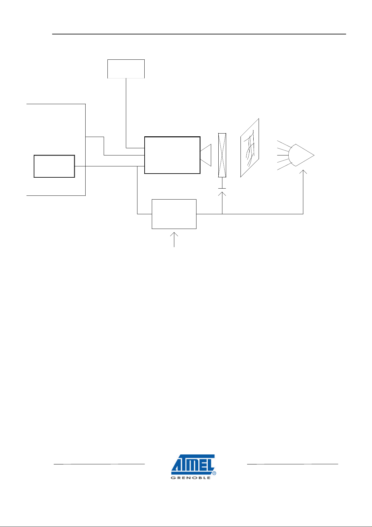
1. IMAGING SYSTEM DESCRIPTION
LIGHTNING
+24V
POWER SUPPLY
CAMELIACOL 2.5M user guide
COMPUTER
SERIAL
FRAME
SHUTTER / CHOPPER
CAMELIA
PORT
POWER
RS232
DATA & SYNC
ANALYZED OBJECT
GRABBER
ELECTRO-OPTICAL
INTERFACE
TRIG_ITC
♦ CAMELIA camera is powered by a +24V power supply.
♦ CAMELIA camera is configured through the serial port of the computer.
♦ CAMELIA camera sends digital video to the FGT frame grabber.
♦ As CAMELIA 's CCD is a full frame sensor, you must use either pulsed lightning or a chopper/shutter in front of
the camera in order to have incident lightning on the CCD only during integration time. You must design an
electro-optical interface to drive camera, shutter/chopper or lightning by using the "SHUTTER" signal delivered
by the camera. If required, the system can send an external trigger or external ITC (integration time control
signal) to the camera.
3/12
Page 4

CAMELIACOL 2.5M user guide
2. CAMELIA COLOR 2.5M CAMERA
2.1 CCD
♦ image format : 35.9mm(V) x 26.5mm(H)
♦ 1840(V) x 1360(H) active pixels
♦ readout register along the small side of the image area. (vertical image)
♦ pixel geometries :
◊ 19.5µm(V) x 19.5µm(H).
♦ filter mosaic : BAYER pattern :
B G B G
G R G R
B G B G
G R G R
◊ note : first active pixel of first active line : blue.
♦ anti-blooming by clocking.
2.2 TIMING
3 timing modes are available :
♦ continuous : the camera delivers frames continuously :
◊ frame N+1 integration starts as soon as frame N readout is completed.
◊ integration time is set by RS232
♦ operation with external trigger : integration start is controlled by the user from the external signal TRIG :
◊ the rising edge of TRIG activates the start of the frame integration. This rising edge is synchronized by
the camera with a precision of 200µs
◊ integration time is set by RS232
◊ note : TRIG signal period must be greater than integration time plus frame readout time.
♦ operation with “ integration time control ” : integration is fully controlled by the user from the external signal ITC :
◊ the falling edge of ITC activates the start of the frame integration. This falling edge is synchronized by the
camera with a precision of 200µs
◊ the rising edge of ITC activates the stop of the frame integration. This rising edge is synchronized by the
camera with a precision of 200µs
◊ note : ITC signal period must be greater than integration time (defined by ITC low) plus frame readout
time.
2x2 and 4x4 pixel binning is possible to enable previewing modes.
When binning is used, the camera delivers black and white video.
Data rate is :
♦ pixel clock : 8 MHz
♦ frame readout time :
◊ normal mode : 340ms
◊ 2x2 pixel binning : 180ms.
◊ 4x4 pixel binning : 100ms.
4/12
Page 5

Timing diagram (for continuous operation) :
CAMELIACOL 2.5M user guide
LEN
FEN
TRIG
LEN
FEN
FRAME
INTEGRATION
INT. TIME SET BY RS232
shutter delay FRAME
video lines
Timing diagram (for operation with ‘’external trigger’’) :
FRAME
INTEGRATION
INT. TIME SET BY RS232
shutter delay
video lines
1360 pixels
1
1360 pixels
READOUT
2
3
READOUT
231
1838
1839
1838
1840
1839
5ms
1840
WAITINGFRAME
Timing diagram (for operation with ‘’integration time control’’) :
ITC
LEN
FEN
FRAME
INTEGRATION
shutter delay
video lines
1360 pixels
2
1
FRAME
READOUT
3
1838
1839
WAITING
1840
5/12
Page 6

CAMELIACOL 2.5M user guide
2.3 ANTI-BLOOMING BY CLOCKING
Anti-blooming can be activated or inhibited (see 2.5.3) :
♦ anti-blooming OFF : this position is recommended if anti-blooming is not required for the application.
♦ anti-blooming ON : anti-blooming operation reduces the pixel saturation charge. As a consequence, camera
gain must be set to 1.30x (see 2.5.3) minimum in order to reach the camera saturation level (4095 adu)
2.4 ELECTRICAL INTERFACES :
2.4.1 POWER SUPPLY :
Voltage Current
+24V
Min : +20V ; Max : +28V
0.6A
2.4.2 DIGITAL I/O
SYMBOL I/O DEFINITION LEVEL
TRIG_ITC I Timing control :
TRIG_ITC is either an external trigger or “ integration time control ”
depending on the timing mode configurated by RS232 (see after)
operation with external trigger :
TRIG_ITC = TRIG
operation with “ integration time control ” :
TRIG_ITC = ITC
TRIG_ITC is synchronized by the camera line clock (jitter : 200 µs)
S(11..0) O Digital video output : 12 bits LVDS
FEN Frame enable :
- FEN = 0 : frame data valid : active lines
- FEN = 1 : frame data not valid
LEN O Line enable :
- LEN = 0 : line data valid : active pixels
- LEN = 1 : line data not valid
PCK O Pixel clock LVDS
SHUTTER O shutter open/close :
- during integration : shutter = 1
- during readout : shutter = 0
delay between the falling edge of shutter and the start of readout :
- 4 positions : 1ms, 5ms, 10ms, 20ms.
LVDS
LVDS
LVDS
LVDS
Note :
♦ LVDS drivers / receivers :
◊ LVDS : Low Voltage differential Signal. (EIA 644 standard). All digital I/Os are differential : (signal+,
signal-). Specifications are given for signal +.
◊ manufacturer NS
◊ driver : DS90C031TM (SO16 package)
◊ receiver : DS90C032TM (SO16 package)
6/12
Page 7

2.4.3 RS232 INTERFACE
Camera configuration is set by RS232 interface. The following features are available :
Function RS232 configuration Comment
Timing mode 3 modes :
- continuous (free running)
- external trigger
- external ITC
Binning 3 modes :
- no binning
- 2x2 pixel binning
- 4x4 pixel binning
CDS gain 2 positions :
- G = 1
- G = 4
Camera gain camera gain value from 1.00x to 2.00x in
16 steps
Shutter control 2 modes :
- active
- inactive (always open)
Shutter delay 4 positions :
- 1ms
- 5ms
- 10ms
- 20ms
Anti-blooming control 2 modes :
- active
- inactive
Integration time integration time value in ms
from 1ms to 2000ms.
image size : 1360(H) x 1840(V)
image size : 680(H) x 920(V)
image size : 340(H) x 460(V)
G = 4 is recommended for
applications requiring high
sensitivity.
Must be an integer.
Ex : 120 for 120ms
120.4 not allowed.
CAMELIACOL 2.5M user guide
Note : video signal processing gain of the camera can be adjusted by setting :
♦ either ‘’CDS gain’’ : a commutation 1x or 4x is available at the input of the video signal processing. Use of the 4x
position is recommended for low level applications (noise is lower)
♦ or ‘’camera gain’’ : a range of 1x to 2x is available in 16 steps.
7/12
Page 8

CAMELIACOL 2.5M user guide
2.5 ELECTRO-OPTICAL PERFORMANCE
♦ Conditions :
◊ frame integration time : 40ms
◊ camera operating free air temperature : 25°C
♦ Performance :
Parameter
Symbol Typical
Value
Unit
Full scale value
VPE 4095 adu
see note 2
Temporal noise
VN 2 adu
σ see note 3
Dark signal non uniformity
DSNU 5 adu
σ see note 4
Dynamic range
DY 2048
see note 5
Responsitivity
@ 3200k
- red channel
- green channel
- blue channel
@ 5200k
- red channel
- green channel
- blue channel
Rr
Rg
Rb
Rr
Rg
Rb
5.5
5.5
4.4
4.2
6.3
7.9
adu/(lux.s)
see note 6
Resolution
- horizontal resolution
- vertical resolution
TBD
TBD
see note 7
♦ note 1 : adu : arbitrary digital unit : 12 bit = 4095 adu or gray levels.
♦ note 2 : full scale value VPE : maximum digital video signal
♦ note 3 : temporal noise VN : r.m.s value in darkness. Measured by substracting 2 images pixel to pixel
♦ note 4 : dark signal non uniformity : r.m.s value. Excludes blemishes.
♦ note 5 : dynamic range DY :
◊ DY = VPE / VN
♦ note 6 : responsitivity :
◊ conditions : BG38 2mm, F/4, lux measured on the scene, camera gain = 1x.
♦ note 7 : resolution :
◊ conditions : light source 3200K, BG38 2mm.
◊ measured at VIDEO = 2000 adu, camera gain = 1x.
8/12
Page 9

10000
8000
CAMELIACOL 2.5M user guide
Spectral responsivity
CAMELIA COLOR 2.5M
6000
4000
2000
Responsivity (ADU/µV/cm²)
0
400 500 600 700
Note : µJ/cm2 measured on the CCD chip.
Including BG38 2mm.
Red
Green
Blue
Wavelength (nm)
9/12
Page 10

CAMELIACOL 2.5M user guide
2.6 GEOMETRICAL SPECIFICATIONS
FRONT PANEL
4 X M3
2 X ø 2.0 mm
64.0 mm
6.0 mm
ø 66.0 mm
74.0 mm
64.0 mm
REAR PANEL
4.0 mm
25.6 mm
2X 1/4_20 UNC 2B
108.0 mm
114.0 mm
144.5 mm
10/12
112.0 mm
DATA & SYNC
TH 31CA179M
SN:
Made in France
RS 232
110.5 mm
POWER
Page 11

CAMELIACOL 2.5M user guide
2.7 ENVIRONMENTAL REQUIREMENTS
♦ operating temperature : 0°C / +50°C
♦ storage temperature : -20°C / 70°C
♦ operating humidity : < 80% at +35°C
♦ vibration : 2g sinusoidal, from 10Hz to 100Hz.
3. CONNECTORS AND CABLES
3.1 ‘’DATA AND SYNC’’ CONNECTOR
50 points 3M connector.
♦ connector reference :HIROSE DX10A-50S.
♦ mating connector on cable side : HIROSE DX40-50P ; shell : HIROSE DX50-CV1.
Pin-out :
Pin n° Signal Pin n° Signal
1 PCK+ 26 LEN+
2 PCK- 27 LEN3 FEN+ 28
4 FEN- 29
5
6
7 PDATA0+ 32 PDATA1+
8 PDATA0- 33 PDATA1-
9 PDATA2+ 34 PDATA3+
10 PDATA2- 35 PDATA311 PDATA4+ 36 PDATA5+
12 PDATA4- 37 PDATA513 PDATA6+ 38 PDATA7+
14 PDATA6- 39 PDATA715 PDATA8+ 40 PDATA9+
16 PDATA8- 41 PDATA917 PDATA10+ 42 PDATA11+
18 PDATA10- 43 PDATA1119 GROUND 44 NC
20 GROUND 45 NC
21 SHUTTER+ 46 TRIG_ITC+
22 SHUTTER- 47 TRIG_ITC23
24
25 NC 50 NC
Notes :
◊ NC : not connected.
◊ (1) : grey cells : not used for CAMELIA COLOR : must be left unconnected
◊ a "Data + Sync" cable is provided with FGT Frame grabber, including a part to be connected to the
electro-optical interface, and the second one to the "FGT" frame grabber : see "FGT Frame Grabber user
manual".
COLOUR_O2+ (1)
COLOUR_O2-(1)
COLOUR_I1+(1)
COLOUR_I1-(1)
30 GROUND
31 GROUND
48
49
COLOUR_O1+ (1)
COLOUR_O1-(1)
COLOUR_I2+(1)
COLOUR_I2-(1)
11/12
Page 12

CAMELIACOL 2.5M user guide
3.2 ’POWER SUPPLY’’ CABLE
♦ On power supply side :
◊ SUBD9 male. Pin out :
Pin
Signal
Number
1 +24V
2 +24V
3 NC
4 NC
5 NC
6 GROUND
7 GROUND
8 NC
9 NC
◊ note : NC : not connected.
3.3 ‘’RS232’’ CABLE
♦ on computer side :
◊ SUBD9 female
◊ pin out compatible with computer serial port
♦ note : pin out is the same on camera side and on computer side.
Information furnished is believed to be accurate and reliable. However Atmel-Grenoble assumes no responsibility for the consequences of
use of such information nor for any infringement of patents or other rights of third parties which may result from its use. No license is
granted by implication or otherwise under any patent rights of Atmel-Grenoble. Specifications mentioned in this publication are subject to
change without notice. This publication supersedes and replaces all information previously supplied. Atmel-Grenoble products are not
authorised for use as critical components in life support devices or systems without express written approval from Atmel-Grenoble.
© 2000 Atmel-Grenoble- Printed in France - All rights reserved.
This product is manufactured by Atmel-Grenoble- 38521 SAINT-EGREVE - FRANCE.
For further information please contact :
Atmel-Grenoble - Route Départementale 128 - 91401 ORSAY Cedex - FRANCE Phone +33 (0)1 69 33 00 00 - Fax +33 (0) 1 69 33 03 21.
Internet : http://www.atmel-grenoble.com
12/12
 Loading...