

Page 1

Operation manual for BLHeli SiLabs Rev5.x
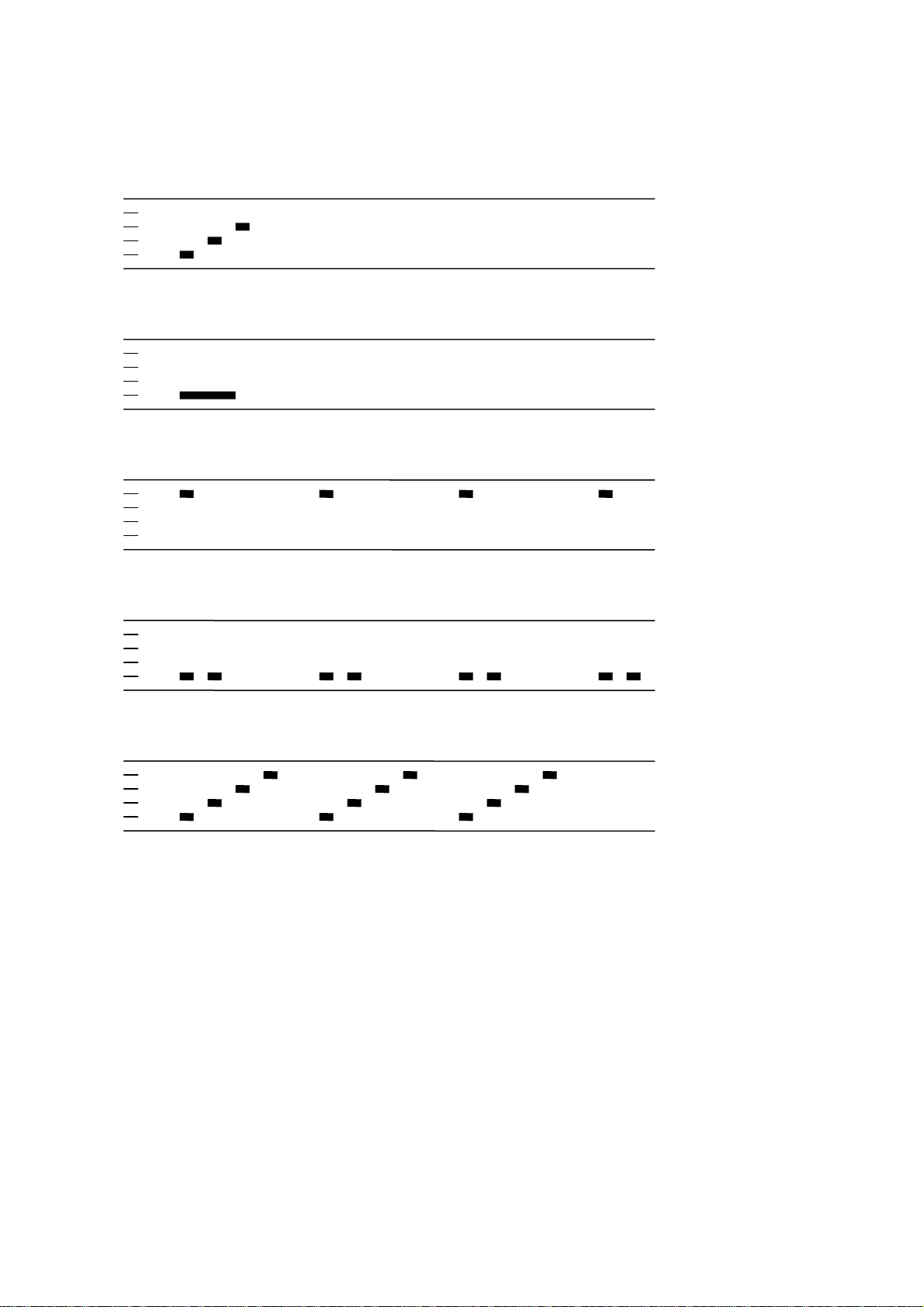
Normal operation:
Power up:
Once
Throttle needs to be minimum before arming starts
Throttle up detected (arming sequence start):
Once
The maximum throttle in this interval sets the”arm” target for the governor.
Zero throttle detected (arming sequence end):
After this, the motor will run.
Once
Document rev 5.x
Page 2
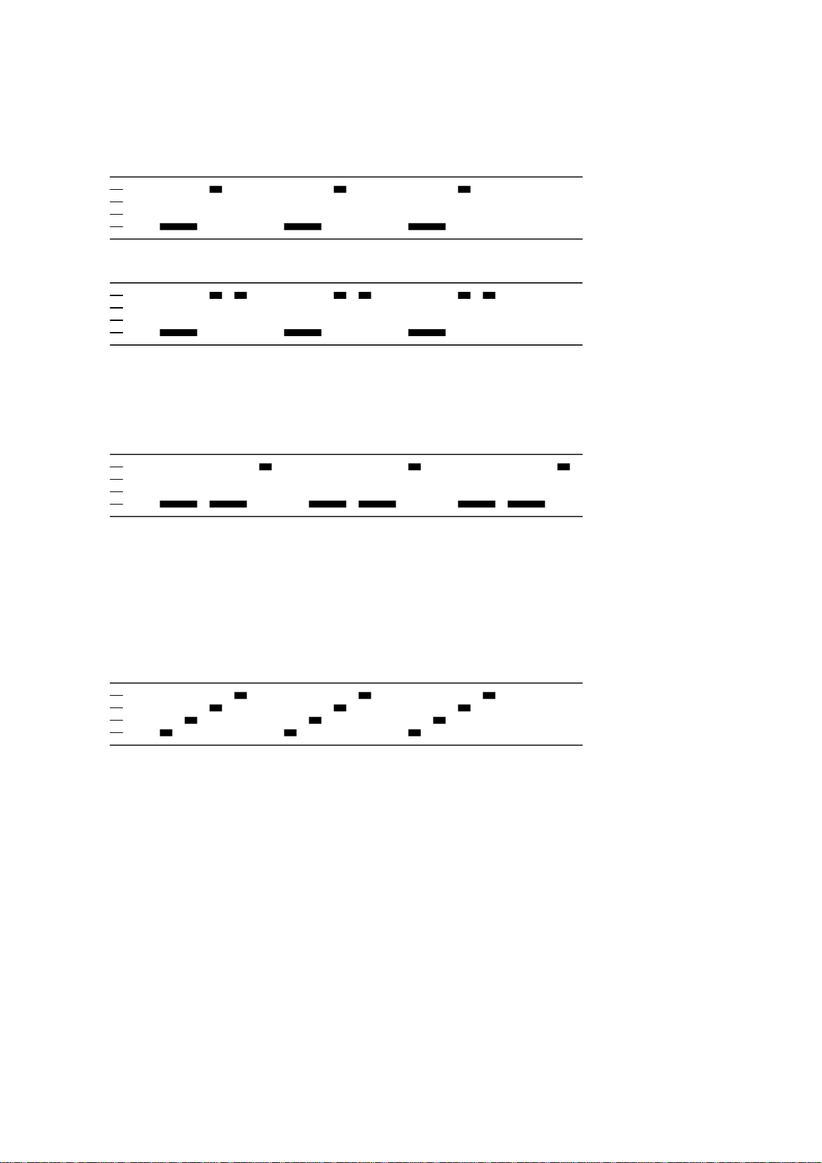
Entering programming mode:
Power up:
Throttle up detected (arming sequence start):
Full throttle detected (start of entering programming mode):
Zero throttle detected (continue entering programming mode):
Once
Once
Infinite
Infinite
Full throttle detected (programming mode entered):
Once
The above description is for main.
For the tail, follow the same sequence, but use right rudder as full throttle and left rudder as
zero throttle.
Document rev 5.x
Page 3
Programming mode:
Function 1, parameter value 1
Function 1, parameter value 2
…etc…
Function 2, parameter value 1
Once
Once
Once
…etc…
If the throttle stick is moved to zero during one of the above sequences, the parameter value
of that function is selected and stored. And you will hear this sound:
Parameter value stored
Once
The ESC then resets itself.
If the throttle stick is moved below max (but not to zero), the current parameter will be
skipped, and programming will proceed to the next parameter. This way it is possible to
access the later parameters without going through all the beeps.
It is generally a good idea to go to full throttle again before selecting a parameter, to make
sure you have selected the right parameter.
Throttle is read in the 1 second pause between the function/parameter beeps.
If the throttle stick is never moved to zero, the ESC will reset itself after the last parameter
value of the last function. Then no changes are done to the programmed values.
If power is disconnected during the programming sequence, then no changes are done to the
programmed values.
Document rev 5.x
Page 4

Programming functions and parameter values:
Programming parameter value table main:
Function 1 2 3 4 5 6 7 8 9 10 11 12 13
1 - Governor P gain 0.13 0.17 0.25 0.38 0.50 0.75 1.00 1.5 2.0 3.0 4.0 6.0 8.0
2 - Governor I gain 0.13 0.17 0.25 0.38 0.50 0.75 1.00 1.5 2.0 3.0 4.0 6.0 8.0
3 - Governor mode Tx Arm Setup Off - - - - - - - - 4 - Low voltage limit 3.0V/cell 3.1V/cell 3.2V/cell 3.3V/cell 3.4V/cell - - - - - - - 5 - Startup power 0.50 0.75 1.00 1.25 1.50 - - - - - - - 6 - Startup rpm 0.67 0.80 1.00 1.25 1.50 - - - - - - - 7 - Startup acceleration 0.4 0.7 1.0 1.5 2.3 - - - - - - - 8 - Commutation timing Low MediumLow Medium MediumHigh
9 - Damping force VeryLow Low MediumLow MediumHigh
10 - Pwm frequency High Low DampedLight
11 - Voltage compensation Off On - - - - - - - - - - 12 - Rotation direction Normal Reversed - - - - - - - - - - 13 - Input pwm polarity Positive Negative - - - - - - - - - - -
- - - - - - - - - -
Programming parameter value table tail:
Function 1 2 3 4 5
1 - Tail gain 0.75 0.88 1.00 1.12 1.25
2 - Tail idle speed Low MediumLow Medium MediumHigh
3 - Startup power 0.50 0.75 1.00 1.25 1.50
4 - Startup rpm 0.67 0.80 1.00 1.25 1.50
5 - Startup acceleration 0.4 0.7 1.0 1.5 2.3
6 - Commutation timing Low MediumLow Medium MediumHigh
7 - Damping force VeryLow Low MediumLow MediumHigh
8 - Pwm frequency High Low DampedLight Damped* 9 - Voltage compensation Off On - - 10 - Rotation direction Normal Reversed - - 11 - Input pwm polarity Positive Negative - - -
*: Only enabled for some ESCs. Default for the ESCs where it is enabled.
Default values are marked in bold
green.
High - - - - - - - High - - - - - - - -
High
High
High
Document rev 5.x
Page 5

Programming parameter value table multi:
Function 1 2 3 4 5
1 - Multi gain 0.75 0.88 1.00 1.12 1.25
2 - Low voltage limit 3.0V/cell 3.1V/cell 3.2V/cell 3.3V/cell 3.4V/cell
3 - Startup power 0.50 0.75 1.00 1.25 1.50
4 - Startup rpm 0.67 0.80 1.00 1.25 1.50
5 - Startup acceleration 0.4 0.7 1.0 1.5 2.3
6 - Commutation timing Low MediumLow Medium MediumHigh
7 - Damping force VeryLow Low MediumLow MediumHigh
8 - Pwm frequency High Low DampedLight Damped* 9 - Voltage compensation Off On - - 10 - Rotation direction Normal Reversed - - 11 - Input pwm polarity Positive Negative - - -
*: Only enabled for some ESCs.
High
High
Default values are marked in bold
green.
If for some reason there is an error in the eeprom/flash write operation (e.g. due to loss of power or low voltage), defaults will be loaded.
Document rev 5.x
Page 6

Programming parameters for main:
In the governor “tx” mode, the throttle value while running sets the speed target for the governor.
In this mode, the throttle curve when flying should be flat.
In the governor “arm” mode the maximum throttle seen during the arming sequence will set the speed target for the governor.
In the governor “setup” mode the governor target is stored in the ESC. It’s default value is 70% (about 4800rpm on mCPX with a 6pole motor
and an 8T pinion). The value can be changed with the “BLHeli setup” program.
In governor “arm” and “setup” modes, the throttle curve when flying does not influence headspeed.
Throttle curve can be set to a V-curve for the desired main to tail mix (this mix is in the mCPX 3in1).
Throttle must be above 20% in these modes. Values below 20% will cause spooldown, and zero will cause stop.
Governor P gain sets the proportional gain for the governor.
This setting controls the gain from speed error to motor power.
Governor I gain sets the integral gain for the governor.
This setting controls the gain from integrated speed error (summed over time) to motor power.
The low voltage limit sets the voltage at which motor power is reduced.
Motor power is reduced while at this voltage, but only temporarily, and full power is resumed if the voltage rises again.
Programming parameters for tail/multi:
Tail/multi gain scales the power applied to the motor for a given input.
Beware that a low tail/multi gain will also limit the maximum power to the motor.
Tail idle speed is the speed of the motor during the delayed stop.
Document rev 5.x
Page 7

Programming parameters for main/tail/multi:
Startup power, rpm and acceleration are parameters that control the startup of the motor for the first initial rotations only (about a second or so).
Startup power sets the power applied to the motor in this phase. Startup rpm sets the rotational speed with which the motor is started. Startup
acceleration sets the rate at which the motor is accelerated. If required, these parameters can be used to optimize motor startup for different
motors and loads.
0
Commutation timing can be adjusted in three steps. Low is about 0
, mediumlow 80, medium 150, mediumhigh 230 and high 300.
Typically a medium setting will work fine, but if the motor stutters it can be beneficial to change timing.
High pwm frequency is around 20-25kHz, and low pwm frequency is around 8-12kHz.
One benefit of using a low pwm frequency is that the step from almost full power to full power becomes smaller. On the other hand, 8kHz is in
the audible frequency range, and also there is a step in power when the motor rotation frequency is equal to the pwm frequency.
Pwm damped mode adds loss to the motor for faster retardation. Damped mode always uses high pwm frequency.
In full damped mode, all three motor terminals are shorted when pwm is off, while in damped light mode, two motor terminals are shorted.
The full damped mode is only supported on some ESCs (where fet switching is sufficiently fast).
If one of the damped modes is selected, then the damping strength can be varied.
If damping is high, loss is added in 7 out of 9 pwm cycles.
If damping is medium high, loss is added in 3 out of 5 pwm cycles.
If damping is medium low, loss is added in 2 out of 5 pwm cycles.
If damping is low, loss is added in 1 out of 5 pwm cycles.
If damping is very low , loss is added in 1 out of 9 pwm cycles.
Damped mode may result in uneven running at low speeds on some motor/ESC/voltage combinations.
This can be seen on high electrical rpm systems, with high damping force and an ESC with slow switching fets.
If this is a problem, reduce the damping force or use an ESC with faster switching fets.
Document rev 5.x
Page 8

Voltage compensation is a feature whereby the voltage is measured and used to compensate motor power. This can have a beneficial effect on
governor speed accuracy. And possibly also tail accuracy.
The rotation direction setting can be used to reverse motor rotation.
The input pwm polarity setting can be used to inverse the throttle behaviour. This is intended to be used with receivers that provide negative
pwm (at least some Walkeras do). When using PPM input it must be set to positive.
Document rev 5.x
Page 9

Arming sequence:
Powe
r
on
Arm start
Max throttle
Arm end
Run
100%
0% Time
The figure below shows an example of throttle value versus time.
during arm
3 beeps
1 low beep
1 high beep
At power on, the ESC beeps 3 beeps.
When throttle is raised above zero, it beeps one low tone beep. This signals the start of the arming sequence.
When throttle is reduced to zero again, it beeps one high tone beep. This signals the end of the arming sequence.
For a main motor esc, throttle is monitored during the arming sequence. The maximum value of throttle is recorded and stored.
If governor arm mode is selected, this value will be used as the governor speed target when the motor starts running.
When running, the throttle input has no effect, as long as it is not below 20%.
Also, if 100% throttle is detected during the arming sequence, the ESC starts entering programming mode.
When restarting main after a stop, there is a 3 second delay from motor stop has been initiated until a new start can commence.
The main motor has a soft spoolup of about 8 seconds for full power.
For PPM input when not in governor arm mode, the arming sequence is skipped. The two beeps will still be there, in order to indicate that the
ESC is armed.
If the esc is armed and sees zero throttle for 30 seconds, it beeps waiting beeps, which are about 1 beep per second
Document rev 5.x
Page 10

Input signal:
The ESC accepts both positive and negative PWM, as well as PPM as input signal.
The type of input signal is auto detected during the arming sequence.
The only input signal that requires changing the default parameters, is negative PWM.
PWM is accepted as 8kHz (mCPX v1), 4kHz, 2kHz (several Walkeras) and 1kHz (mCPX v2).
PPM has a fixed throttle range of 1050us-1866us, and accepts rates from the normal 50Hz up to several hundred Hz.
Thermal protection:
The ESC measures temperature within the MCU and limits motor power if the temperature is too high.
Motor power is limited in four steps:
- If the temperature is above 1400C, motor power is limited to 75%.
- If the temperature is above 145
- If the temperature is above 150
- If the temperature is above 155
Note: The above is valid for rev4.1 and up. For rev4.0, these limits were 85
0
C, motor power is limited to 50%.
0
C, motor power is limited to 25%.
0
C, motor power is limited to 0%.
0
C to 1300C
Document rev 5.x
Page 11

Revision history:
- Rev1.0: Initial revision based upon BLHeli for AVR controllers
- Rev2.0: Changed "Eeprom" initialization, layout and defaults
Various changes and improvements to comparator reading. Now using timer1 for time from pwm on/off
Beeps are made louder
Added programmable low voltage limit
Added programmable damped tail mode (only for 1S ESCs)
Added programmable motor rotation direction
- Rev2.1: (minor changes by 4712)
Added Disable TX Programming by PC Setup Application
therfore changed EEPROM_LAYOUT_REVISION = 8
Added Vdd Monitor as reset source when writing to "EEProm"
Changed for use of batch file to assemble, link and make hex files
- Rev2.2: (minor changes by 4712)
Added Disable Throttle Re-Arming every motor start by PC Setup Application
- Rev2.3: (minor changes by 4712)
Added bugfixed (2x CLR C before j(n)c operations)thx Steffen!
- Rev2.4: Revisions 2.1 to 2.3 integrated
- Rev3.0: Added PPM (1050us-1866us) as accepted input signal
Added startup rpm as a programming parameter
Added startup acceleration as a programming parameter
Added option for using voltage measurements to compensate motor power
Added governor target by setup as a governor mode option
Governor is kept active regardless of rpm
Smooth governor spoolup/down in arm and setup modes
Increased governor P and I gain programming ranges
Increased and changed low voltage limit programming range
Disabled tx programming entry for all but the first arming sequence after power on
Made it possible to skip parameters in tx programming by setting throttle midstick
Made it default not to rearm for every restart
- Rev3.1: Fixed bug that prevented chosen parameter to be set in tx programming
Document rev 5.x
Page 12

- Rev3.2: ...also updated the EEPROM revision parameter
- Rev3.3: Fixed negative number bug in voltage compensation
Fixed bug in startup power calculation for non-default power
Prevented possibility for voltage compensation fighting low voltage limiting
Applied overall spoolup control to ensure soft spoolup in any mode
Added a delay of 3 seconds from initiation of main motor stop until new startup is allowed
Reduced beep power to reduce power consumption for very strong motors/ESCs
- Rev3.4: Fixed bug that prevented full power in governor arm and setup modes
Increased NFETON_DELAY for XP_7A and XP_12A to allow for more powerful fets
Increased initial spoolup power, and linked to startup power
- Rev4.0: Fixed bug that made tail tx program beeps very weak
Added thermal protection feature
Governor P and I gain ranges are extended up to 8.0x gain
Startup sequence is aborted upon zero throttle
Avoided voltage compensation function induced latency for tail when voltage compensation is not enabled
Improved input signal frequency detection robustness
- Rev4.1: Increased thermal protection temperature limits
- Rev5.0: Added multi(copter) operating mode. TAIL define changed to MODE with three modes: MAIN, TAIL and MULTI
Added programmable commutation timing
Added a damped light mode that has less damping, but that can be used with all escs
Added programmable damping force
Added thermal protection for startup too
Added wait beeps when waiting more than 10 sec for throttle above zero (after having been armed)
Modified tail idling to provide option for very low speeds
Changed PPM range to 1150-1830us
Arming sequence is dropped for PPM input, unless it is governor arm mode
Loss of input signal will immediately stop the motor for PPM input
Bug corrected in Turnigy Plush 6A voltage measurement setup
FET switching delays are set for original fets. Stronger/doubled/tripled etc fets may require faster pfet off switching
Miscellaneous other changes
Document rev 5.x
 Loading...