

Page 1

Operation manual for BLHeli SiLabs Rev3.x
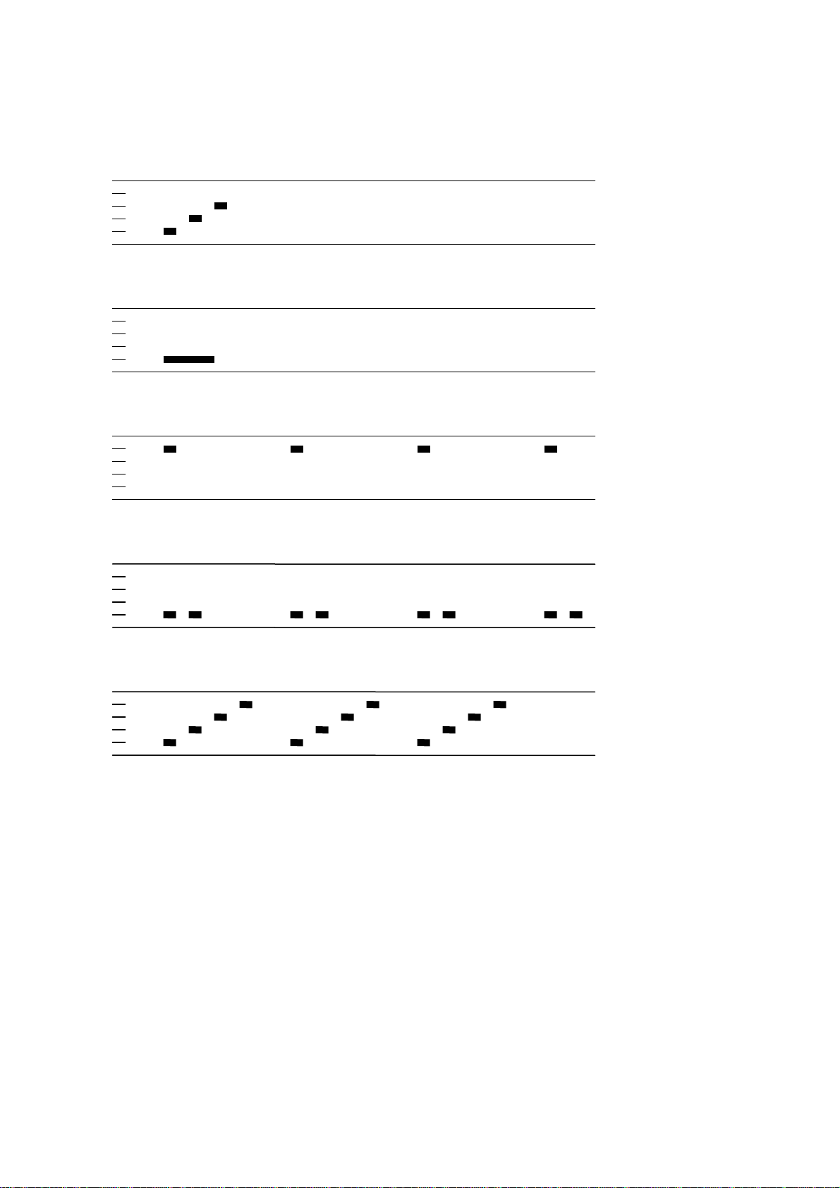
Normal operation:
Power up:
Once
Throttle needs to be minimum before arming starts
Throttle up detected (arming sequence start):
Once
The maximum throttle in this interval sets the”arm” target for the governor.
Zero throttle detected (arming sequence end):
After this, the motor will run.
Once
Document rev 3.x
Page 2
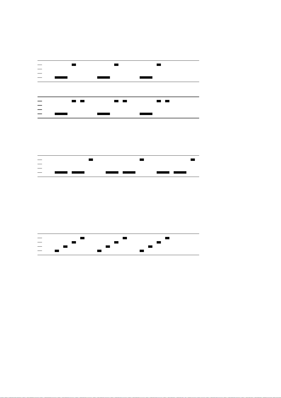
Entering programming mode:
Power up:
Throttle up detected (arming sequence start):
Full throttle detected (start of entering programming mode):
Zero throttle detected (continue entering programming mode):
Once
Once
Infinite
Infinite
Full throttle detected (programming mode entered):
Once
The above description is for main.
For the tail, follow the same sequence, but use right rudder as full throttle and left rudder as
zero throttle.
Document rev 3.x
Page 3
Programming mode:
Function 1, parameter value 1
Function 1, parameter value 2
…etc…
Function 2, parameter value 1
Once
Once
Once
…etc…
If the throttle stick is moved to zero during one of the above sequences, the parameter value
of that function is selected and stored. And you will hear this sound:
Parameter value stored
Once
The ESC then resets itself.
If the throttle stick is moved below max (but not to zero), the current parameter will be
skipped, and programming will proceed to the next parameter. This way it is possible to
access the later parameters without going through all the beeps.
It is generally a good idea to go to full throttle again before selecting a parameter, to make
sure you have selected the right parameter.
Throttle is read in the 1 second pause between the function/parameter beeps.
If the throttle stick is never moved to zero, the ESC will reset itself after the last parameter
value of the last function. Then no changes are done to the programmed values.
If power is disconnected during the programming sequence, then no changes are done to the
programmed values.
Document rev 3.x
Page 4

Programming functions and parameter values:
Programming parameter value table main:
Function 1 2 3 4 5 6 7 8 9
1 - Governor P gain 0.13 0.17 0.25 0.38 0.50 0.75
2 - Governor I gain 0.13 0.17 0.25 0.38 0.50 0.75
3 - Governor mode
4 – Low voltage limit 3.0V/cell 3.1V/cell
5 - Startup power 0.50 0.75
6 - Startup rpm 0.67 0.80
7 - Startup acceleration
8 - Pwm frequency High
9 - Voltage compensation
10 - Rotation direction
11 - Input pwm polarity
Tx
0.4
Off
Normal
Positive
Arm Setup Off - - - - -
3.2V/cell
1.00
1.00
0.7 1.0 1.5 2.3 - - - -
Low
On - - - - - - Reversed - - - - - - Negative - - - - - - -
- - - - - - -
3.3V/cell 3.4V/cell - - - -
1.25 1.50 - - - -
1.25 1.50 - - - -
1.00
1.00
Programming parameter value table tail:
Function 1 2 3 4 5
1 - Tail gain 0.75 0.88
2 - Tail idle speed Low MediumLow
3 - Startup power 0.50 0.75
4 - Startup rpm 0.67 0.80
5 - Startup acceleration 0.4 0.7 1.0 1.5
6 - Pwm frequency
7 - Voltage compensation
8 - Rotation direction
9 - Input pwm polarity
*: Only enabled for ESCs specified for 1S operation only. Default for the ESCs where it is enabled.
High
Off
Normal
Positive
Low
On - - Reversed - - Negative - - -
1.00
Medium
1.00
1.00
Damped*
1.12 1.25
MediumHigh
1.25 1.50
1.25 1.50
- -
High
2.3
Default values are marked in bold green.
If for some reason there is an error in the eeprom/flash write operation (e.g. due to loss of power or low voltage), defaults will be loaded.
1.50 2.00
1.50 2.00
Document rev 3.x
Page 5

Programming parameters for main:
In the governor “tx” mode, the throttle value while running sets the speed target for the governor.
In this mode, the throttle curve when flying should be flat.
In the governor “arm” mode the maximum throttle seen during the arming sequence will set the speed target for the governor.
In the governor “setup” mode the governor target is stored in the ESC. It’s default value is 70% (about 4800rpm on mCPX with a 6pole motor
and an 8T pinion). The value can be changed with the “BLHeli setup” program.
In governor “arm” and “setup” modes, the throttle curve when flying does not influence headspeed.
Throttle curve can be set to a V-curve for the desired main to tail mix (this mix is in the mCPX 3in1).
Throttle must be above 20% in these modes. Values below 20% will cause spooldown, and zero will cause stop.
Governor P gain sets the proportional gain for the governor.
This setting controls the gain from speed error to motor power.
Governor I gain sets the integral gain for the governor.
This setting controls the gain from integrated speed error (summed over time) to motor power.
The low voltage limit sets the voltage at which motor power is reduced.
Motor power is reduced while at this voltage, but only temporarily, and full power is resumed if the voltage rises again.
Programming parameters for tail:
Tail gain scales the power applied to the tail motor for a given input.
Beware that a low tail gain will also limit the maximum power to the tail.
Tail idle speed is the speed of the tail motor during the delayed stop.
Document rev 3.x
Page 6

Programming parameters for main/tail:
Startup power, rpm and acceleration are parameters that control the startup of the motor for the first initial rotations only (about a second or so).
Startup power sets the power applied to the motor in this phase. Startup rpm sets the rotational speed with which the motor is started. Startup
acceleration sets the rate at which the motor is accelerated. If required, these parameters can be used to optimize motor startup for different
motors and loads.
High pwm frequency is around 20-25kHz, and low pwm frequency is around 8-12kHz.
One benefit of using a low pwm frequency is that the step from almost full power to full power becomes smaller. On the other hand, 8kHz is in
the audible frequency range, and also there is a step in power when the motor rotation frequency is equal to the pwm frequency.
The damped pwm mode for the tail makes the motor retardation much faster.
It is only supported on some ESCs (where both nfets and pfets are driven directly from the MPU).
Voltage compensation is a feature whereby the voltage is measured and used to compensate motor power. This can have a beneficial effect on
governor speed accuracy. And possibly also tail accuracy.
The rotation direction setting can be used to reverse motor rotation.
The input pwm polarity setting can be used to inverse the throttle behaviour. This is intended to be used with receivers that provide negative
pwm (at least some Walkeras do). When using PPM input it must be set to positive.
Document rev 3.x
Page 7

Arming sequence:
Powe
r
on
Arm start
Max throttle
Arm end
Run
100%
0% Time
The figure below shows an example of throttle value versus time.
during arm
3 beeps
1 low beep
1 high beep
At power on, the ESC beeps 3 beeps.
When throttle is raised above zero, it beeps one low tone beep. This signals the start of the arming sequence.
When throttle is reduced to zero again, it beeps one high tone beep. This signals the end of the arming sequence.
During the arming sequence, throttle is monitored. The maximum value of throttle is recorded and stored.
If governor arm mode is selected, this value will be used as the governor speed target when the motor starts running.
When running, the throttle input has no effect, as long as it is not below 20%.
Also, if 100% throttle is detected during the arming sequence, the ESC starts entering programming mode.
The following applies for codes Rev3.3 and later:
When restarting main after a stop, there is a 3 second delay from motor stop has been initiated until a new start can commence.
The main motor has a soft spoolup of about 8 seconds for full power.
Document rev 3.x
Page 8

Input signal:
The ESC accepts both positive and negative PWM, as well as PPM as input signal.
The type of input signal is auto detected during the arming sequence.
The only input signal that requires changing the default parameters, is negative PWM.
PWM is accepted as 8kHz (mCPX v1), 4kHz, 2kHz (several Walkeras) and 1kHz (mCPX v2).
PPM has a fixed throttle range of 1050us-1866us, and accepts rates from the normal 50Hz up to several hundred Hz.
Document rev 3.x
 Loading...