

Page 1
Operation manual for BLHeli SiLabs Rev2.x
Normal operation:
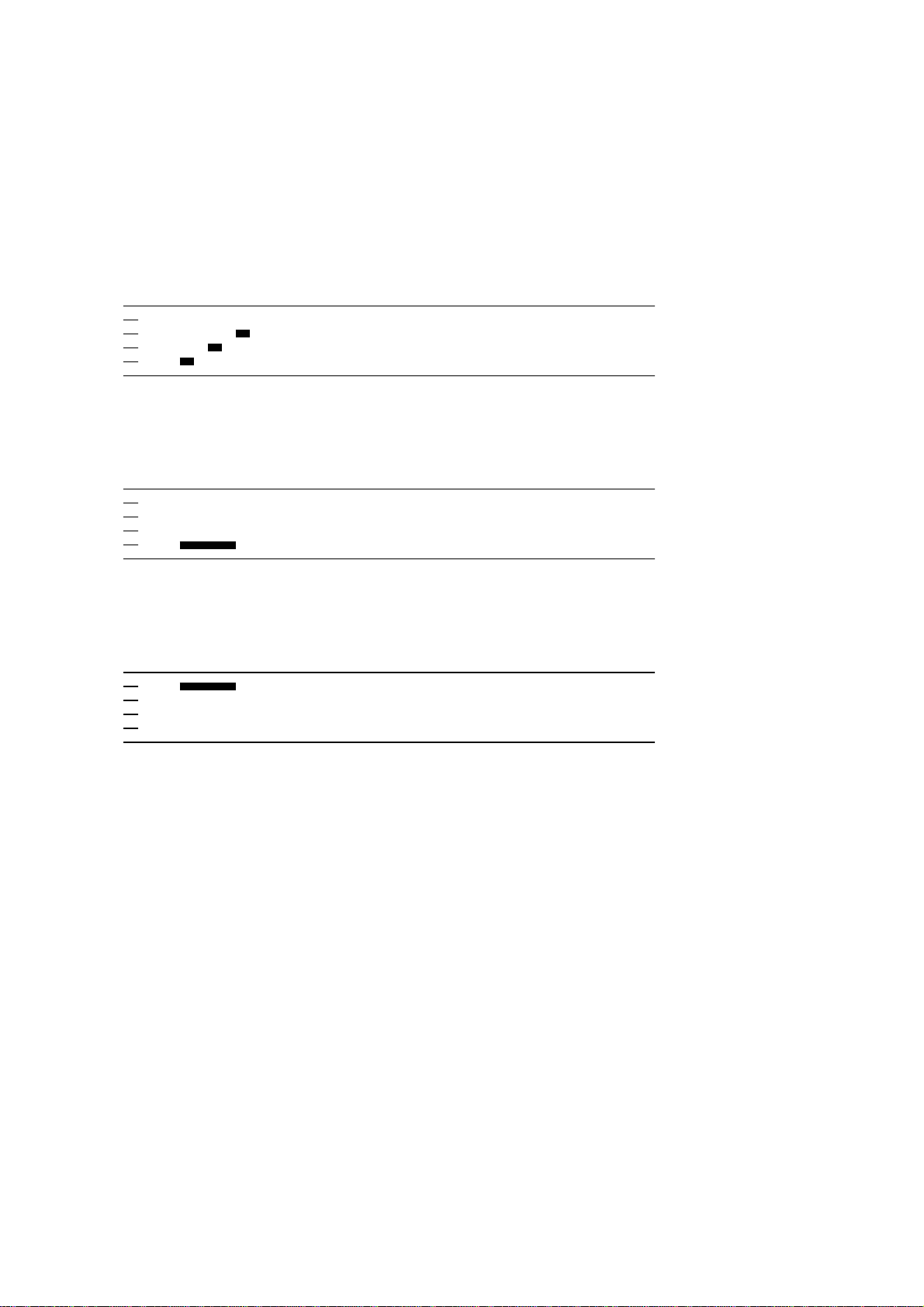
Power up:
Once
Throttle needs to be minimum before arming starts
Throttle up detected (arming sequence start):
Once
The maximum throttle in this interval sets the”arm” target for the governor.
Zero throttle detected (arming sequence end):
After this, the motor will run.
Once
Document rev 2.x
Page 2
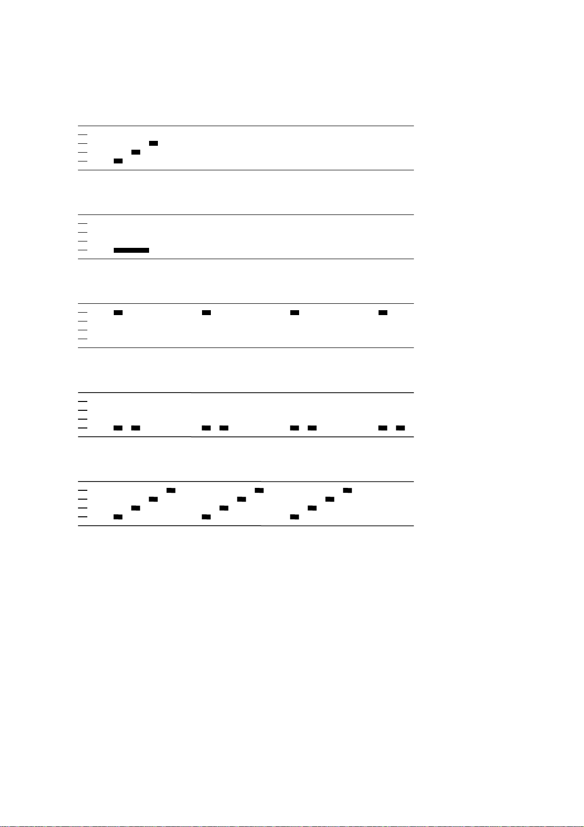
Entering programming mode:
Power up:
Throttle up detected (arming sequence start):
Full throttle detected (start of entering programming mode):
Zero throttle detected (continue entering programming mode):
Once
Once
Infinite
Full throttle detected (programming mode entered):
Infinite
Once
Document rev 2.x
Page 3

Programming mode:
Function 1, parameter value 1
Function 1, parameter value 2
…etc…
Function 2, parameter value 1
Once
Once
Once
…etc…
If the throttle stick is moved to zero during one of the above sequences, the parameter value
of that function is selected and stored. And you will hear this sound:
Parameter value stored
Once
The ESC then resets itself.
If the throttle stick is never moved to zero, the ESC will reset itself after the last parameter
value of the last function. Then no changes are done to the programmed values.
If power is disconnected during the programming sequence, then no changes are done to the
programmed values.
Document rev 2.x
Page 4

Programming functions and parameter values:
Programming parameter value table main:
Function 1 2 3 4 5
1 - Governor P gain 0.38 0.50 0.75
2 - Governor I gain 0.38 0.50 0.75
3 - Governor mode
4 – Low voltage limit 2.7V/cell
5 - Startup power 0.50 0.75
6 - Pwm frequency High
7 - Rotation direction
8 - Input pwm polarity
Tx
Normal
Positive
Arm Off - -
3.0V/cell
Low
Reversed - - Negative - - -
3.3V/cell - -
1.00
- - -
1.00
1.00
1.25 1.50
Programming parameter value table tail:
Function 1 2 3 4 5
1 - Tail gain 0.75 0.88
2 - Tail idle speed Low MediumLow
3 - Startup power 0.50 0.75
4 - Pwm frequency
5 - Rotation direction
6 - Input pwm polarity
*: Only enabled for ESCs specified for 1S operation only. Default for the ESCs where it is enabled.
High
Normal
Positive
Low
Reversed - - Negative - - -
1.00
Medium
1.00
Damped*
1.12 1.25
MediumHigh High
1.25 1.50
- -
Default values are marked in bold green.
In the governor “tx” mode, the throttle setting will set the speed target for the governor.
In this mode, the throttle curve when flying should be flat.
In the governor “arm” mode the maximum throttle seen during the arming sequence will set
the speed target for the governor.
In this mode, the throttle curve when flying does not influence headspeed.
Throttle curve can be set for the desired main to tail mix (this mix is in the mCPX 3in1)
Governor P gain sets the proportional gain for the governor.
This setting controls the gain from speed error to motor power.
Governor I gain sets the integral gain for the governor.
This setting controls the gain from integrated speed error (summed over time) to motor power.
1.50
1.50
Document rev 2.x
Page 5

Tail gain scales the power applied to the tail motor for a given input.
Beware that a low tail gain will also limit the maximum power to the tail.
Tail idle speed is the speed of the tail motor during the delayed stop.
High pwm frequency is around 20-25kHz, and low pwm frequency is around 8-12kHz.
One benefit of using a low pwm frequency is that the step from almost full power to full
power becomes smaller. On the other hand, 8kHz is in the audible frequency range.
The damped pwm mode for the tail makes the motor retardation much faster.
It is only supported on some ESCs (where both nfets and pfets are driven directly from the
MPU) .
If for some reason there is an error in the eeprom/flash write operation (e.g. due to loss of
power or low voltage), defaults will be loaded.
Document rev 2.x
 Loading...