

Page 1
SmartConnect Bluetooth
ATBTLC1000 Xplained Pro
USER GUIDE
Preface
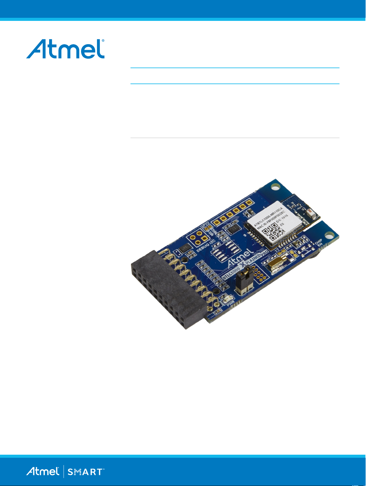
Atmel® ATBTLC1000 Xplained Pro is an extension board in the Atmel
Xplained Pro evaluation platform. It is designed to demonstrate ultra-low
power Bluetooth® SMART (BLE 4.1) ATBTLC1000 together with Xplained
Pro MCU boards.
Atmel-42538B-BTLC1000-Xplained-Pro_User Guide-11/2015
Page 2

Table of Contents
Preface............................................................................................................................ 1
1. Introduction................................................................................................................3
1.1. Features....................................................................................................................................... 3
1.2. Kit Overview................................................................................................................................. 3
2. Getting Started...........................................................................................................5
2.1. Xplained Pro Quick Start.............................................................................................................. 5
3. Design Documentation and Relevant Links...............................................................6
4. Xplained Pro.............................................................................................................. 7
4.1. Hardware Identification System....................................................................................................7
4.2. Xplained Pro Headers and Connectors........................................................................................7
4.2.1. Xplained Pro Standard Extension Header..................................................................... 7
5. Hardware Users Guide.............................................................................................. 9
5.1. Electrical Characteristics.............................................................................................................. 9
5.2. Headers and Connectors..............................................................................................................9
5.2.1. ATBTLC1000 Xplained Pro Extension Header..............................................................9
5.2.2. Current Measurement Header..................................................................................... 10
5.2.3. Debug Connectors.......................................................................................................10
5.3. Peripherals..................................................................................................................................11
5.3.1. External Flash.............................................................................................................. 11
5.3.2. Temperature Sensor.....................................................................................................11
5.3.3. Power LED...................................................................................................................12
5.3.4. Reset Switch................................................................................................................12
5.3.5. 32kHz RTC Oscillator.................................................................................................. 12
6. Hardware Revision History and Known Issues........................................................13
6.1. Identifying Product ID and Revision........................................................................................... 13
6.2. Revision 2...................................................................................................................................13
7. Document Revision History..................................................................................... 15
8. Evaluation Board/kit Important Notice..................................................................... 16
Atmel ATBTLC1000 Xplained Pro [USER GUIDE]
Atmel-42538B-BTLC1000-Xplained-Pro_User Guide-11/2015
2
Page 3

1. Introduction
1.1. Features
• ATBTLC1000-MR110CA Bluetooth module
– Complies with Bluetooth V4.1, ETSI EN 300 328 and EN 300 440 Class 2, FCC CFR47 Part
15, and ARIB STD-T66
– ARM® Cortex®-M0 32-bit processor
• AT30TSE758A Digital Temperature Sensor
– Integrated temperature sensor + nonvolatile registers + serial EEPROM
– 2-Wire I2C and SMBus compatible serial interface
• Xplained Pro hardware identification system using ATSHA204A
• Power LED
• Power debugger support using current measurement header
• Provision for external flash (footprint only). Recommended MPN: IS25LD020-JNLE.
• Debug I2C header
• Debug UART/SPI extension port
• CHIP EN switch for ATBTLC1000 module (footprint only)
• SWD header
• 32kHz crystal
1.2. Kit Overview
The Atmel ATBTLC1000 Xplained Pro is an extension board containing the Atmel ultra-low power
Bluetooth module ATBTLC1000-MR110CA for the Xplained Pro platform. The kit can be connected to any
extension header on an Xplained Pro MCU Board.
Atmel ATBTLC1000 Xplained Pro [USER GUIDE]
Atmel-42538B-BTLC1000-Xplained-Pro_User Guide-11/2015
3
Page 4
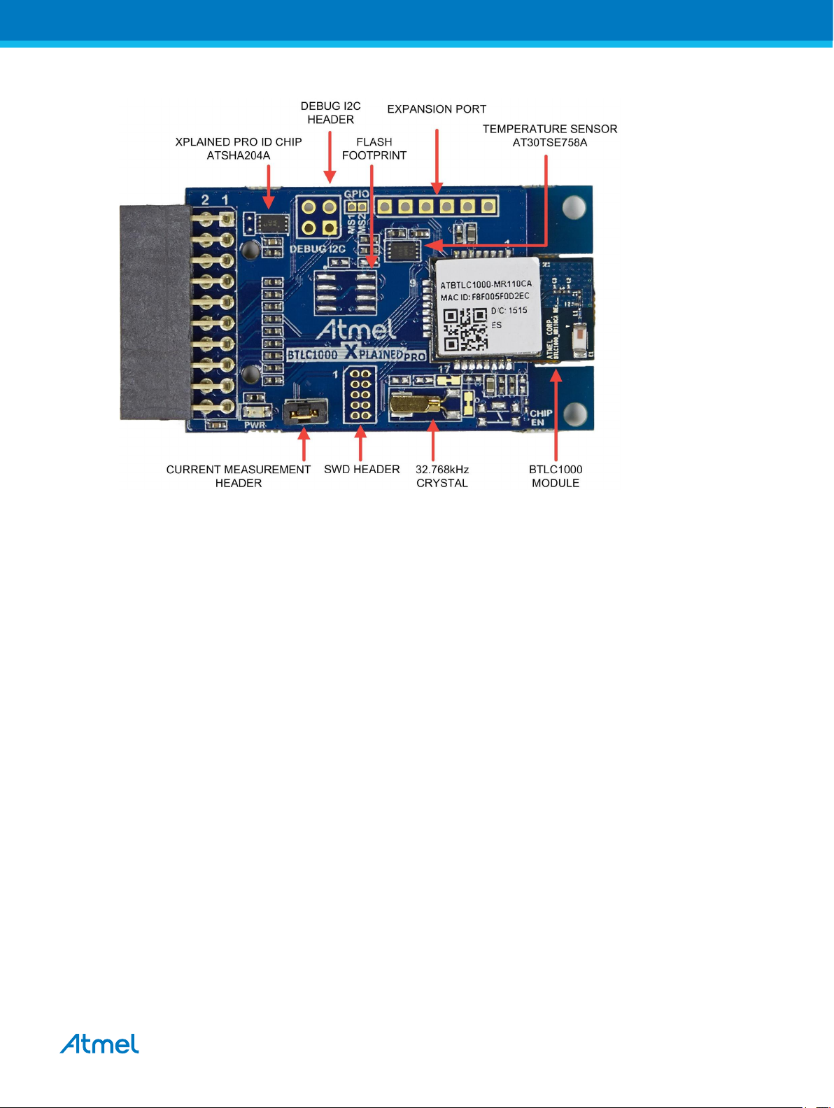
Figure 1-1 ATBTLC1000 Xplained Pro Extension Board
Atmel ATBTLC1000 Xplained Pro [USER GUIDE]
Atmel-42538B-BTLC1000-Xplained-Pro_User Guide-11/2015
4
Page 5

2. Getting Started
2.1. Xplained Pro Quick Start
Three steps to start exploring the Atmel Xplained Pro platform:
1. Download Atmel Studio.
2. Launch Atmel Studio.
3. Connect ATBTLC1000 Xplained Pro to an Xplained Pro MCU board and connect a USB cable to
the DEBUG USB port on the Xplained Pro MCU board.
When the Xplained Pro MCU kit is connected to your computer for the first time, the operating system will
perform a driver software installation. The driver file supports both 32- and 64-bit versions of Microsoft
®
Windows® XP, Windows Vista®, Windows 7, and Windows 8.
Once the Xplained Pro MCU board is powered the green power LED will be lit and Atmel Studio will auto
detect which Xplained Pro MCU- and extension board(s) are connected. Atmel Studio will present
relevant information like datasheets and kit documentation. The kit landing page in Atmel Studio also has
the option to launch Atmel Software Framework (ASF) example applications for the kit. The target device
is programmed and debugged by the on-board Embedded Debugger and therefore no external
programmer or debugger tool is needed.
Atmel ATBTLC1000 Xplained Pro [USER GUIDE]
Atmel-42538B-BTLC1000-Xplained-Pro_User Guide-11/2015
5
Page 6

3. Design Documentation and Relevant Links
The following list contains links to the most relevant documents and software for ATBTLC1000 Xplained
Pro:
• Xplained Pro products - Atmel Xplained Pro is a series of small-sized and easy-to-use evaluation
kits for Atmel microcontrollers and other Atmel products. It consists of a series of low-cost MCU
boards for evaluation and demonstration of features and capabilities of different MCU families.
• Atmel Studio - Free Atmel IDE for development of C/C++ and assembler code for Atmel
microcontrollers.
• EDBG User Guide - User guide containing more information about the on-board Embedded
Debugger.
• Atmel Data Visualizer - Atmel Data Visualizer is a program used for processing and visualizing
data. Data Visualizer can receive data from various sources such as the Embedded Debugger Data
Gateway Interface found on Xplained Pro boards and COM ports.
• Atmel Software Framework - MCU software library providing a large collection of embedded
software for Atmel flash MCUs.
• Hardware Users Guide in PDF format - PDF version of this User Guide.
• Design Documentation - Package containing CAD source, schematics, BOM, assembly drawings,
3D plots, layer plots etc.
• ATBTLC1000 Xplained Pro on Atmel website - Atmel website link.
• ATBTLC1000 BluSDK - Software, firmware, applications, and tools packages. Located in the
software section of the page.
Atmel ATBTLC1000 Xplained Pro [USER GUIDE]
Atmel-42538B-BTLC1000-Xplained-Pro_User Guide-11/2015
6
Page 7

4. Xplained Pro
Xplained Pro is an evaluation platform that provides the full Atmel microcontroller experience. The
platform consists of a series of Microcontroller (MCU) boards and extension boards, which are integrated
with Atmel Studio, have Atmel Software Framework (ASF) drivers and demo code, support data
streaming, and more. Xplained Pro MCU boards support a wide range of Xplained Pro extension boards,
which are connected through a set of standardized headers and connectors. Each extension board has
an identification (ID) chip to uniquely identify which boards are connected to an Xplained Pro MCU board.
This information is used to present relevant user guides, application notes, datasheets, and example
code through Atmel Studio.
4.1. Hardware Identification System
All Xplained Pro compatible extension boards have an Atmel ATSHA204 CryptoAuthentication™ chip
mounted. This chip contains information that identifies the extension with its name and some extra data.
When an Xplained Pro extension is connected to an Xplained Pro MCU board the information is read and
sent to Atmel Studio. The Atmel Kits extension, installed with Atmel Studio, will give relevant information,
code examples, and links to relevant documents. Table 4-1 Xplained Pro ID Chip Content on page 7
shows the data fields stored in the ID chip with example content.
Table 4-1 Xplained Pro ID Chip Content
Data field Data type Example content
Manufacturer ASCII string Atmel'\0'
Product Name ASCII string Segment LCD1 Xplained Pro'\0'
Product Revision ASCII string 02'\0'
Product Serial Number ASCII string 1774020200000010’\0’
Minimum Voltage [mV] uint16_t 3000
Maximum Voltage [mV] uint16_t 3600
Maximum Current [mA] uint16_t 30
4.2. Xplained Pro Headers and Connectors
4.2.1. Xplained Pro Standard Extension Header
All Xplained Pro kits have one or more dual row, 20-pin, 100mil extension header. Xplained Pro MCU
boards have male headers, while Xplained Pro extensions have their female counterparts. Note that all
pins are not always connected. All connected pins follow the defined pin-out description in Table 4-2
Xplained Pro Standard Extension Header on page 8.
The extension headers can be used to connect a variety of Xplained Pro extensions to Xplained Pro MCU
boards or to access the pins of the target MCU on Xplained Pro MCU boards directly.
Atmel ATBTLC1000 Xplained Pro [USER GUIDE]
Atmel-42538B-BTLC1000-Xplained-Pro_User Guide-11/2015
7
Page 8

Table 4-2 Xplained Pro Standard Extension Header
Pin number Name Description
1 ID Communication line to the ID chip on an extension board
2 GND Ground
3 ADC(+) Analog to digital converter, alternatively positive part of differential
ADC
4 ADC(-) Analog to digital converter, alternatively negative part of differential
ADC
5 GPIO1 General purpose I/O
6 GPIO2 General purpose I/O
7 PWM(+) Pulse width modulation, alternatively positive part of differential
PWM
8 PWM(-) Pulse width modulation, alternatively negative part of differential
PWM
9 IRQ/GPIO Interrupt request line and/or general purpose I/O
10 SPI_SS_B/
Slave select for SPI and/or general purpose I/O
GPIO
11 I2C_SDA Data line for I2C interface. Always implemented, bus type.
12 I2C_SCL Clock line for I2C interface. Always implemented, bus type.
13 UART_RX Receiver line of target device UART
14 UART_TX Transmitter line of target device UART
15 SPI_SS_A Slave select for SPI. Should preferably be unique.
16 SPI_MOSI Master out slave in line of serial peripheral interface. Always
implemented, bus type.
17 SPI_MISO Master in slave out line of serial peripheral interface. Always
implemented, bus type.
18 SPI_SCK Clock for serial peripheral interface. Always implemented, bus type.
19 GND Ground
20 VCC Power for extension board
Atmel ATBTLC1000 Xplained Pro [USER GUIDE]
Atmel-42538B-BTLC1000-Xplained-Pro_User Guide-11/2015
8
Page 9

5. Hardware Users Guide
5.1. Electrical Characteristics
ATBTLC1000 Xplained Pro can be connected to several Xplained Pro MCU boards and manually
connected to other hardware. Xplained Pro MCU board(s) that does not have 3.3V as it's primary target
voltage will read all ID devices on connected extensions to check if they support the target voltage before
enabling it to the extension headers. The table below shows the static content written in the ID chip.
Table 5-1 ATBTLC1000 Xplained Pro ID Chip Content
Data field Content
Product name ATBTLC1000-XPRO
Minimum operation voltage 1.8V
Maximum operation voltage 3.6V
Maximum current 10mA
Related Links
Hardware Identification System on page 7
5.2. Headers and Connectors
5.2.1. ATBTLC1000 Xplained Pro Extension Header
ATBTLC1000 Xplained Pro implements one Xplained Pro Standard Extension Header marked with EXT1
in silkscreen. This header makes it possible to connect the board to an Xplained Pro MCU board. The
pin-out definition for the extension header can be seen in the table below.
Table 5-2 ATBTLC1000 Xplained Pro Extension Header EXT1
Pin on EXT1 Function Description
1 ID Communication line to the ID chip
2 GND Ground
3 NC Not Connected
4 NC Not Connected
5 NC Not Connected
6 GPIO/WAKE Always-on External Wakeup
7 NC Not Connected
8 PWM-/RTC_CLKP 32.768kHz RTC Clock (optional feature)
9 GPIO_MS1 Mixed signal/Analog interface pin
10 GPIO/CHIP_EN Master Enable for chip
11 TWI_SDA I2C SDA
Atmel ATBTLC1000 Xplained Pro [USER GUIDE]
Atmel-42538B-BTLC1000-Xplained-Pro_User Guide-11/2015
9
Page 10

Pin on EXT1 Function Description
12 TWI_SCL I2C SCL
13 UART_TX UART TX
14 UART_RX UART RX
15 SPI_SS_A SPI SS
16 SPI_MOSI SPI MOSI
17 SPI_MISO SPI MISO
18 SPI_SCK SPI Clock
19 GND Ground
20 VCC Target supply voltage
Related Links
Xplained Pro Standard Extension Header on page 7
5.2.2. Current Measurement Header
Current Measurement header J101 can be used to measure the current consumed by the ATBTLC1000
module using an ammeter. The two 0Ω resistors R112 and R113 can be removed to measure the current
consumed by individual power rails VDDIO and VBAT respectively by soldering in wires for an ammeter.
5.2.3. Debug Connectors
Debug I2C (J104) and Extension port (J105) are not mounted on the board. Extension port J105 can be
configured as Debug UART or as SPI to connect to external sensors. Refer to the ATBTLC1000MR110CA datasheet for reference.
Table 5-3 Debug I2C Connector
Pin on I2C connector Pin on ATBTLC1000 module Function
1 8 I2C SCL
2 1 Ground
3 7 I2C SDA
4 - Not Connected
Table 5-4 Extension Port
Pin on Extension Port Pin on ATBTLC1000 module Function
1 4 UART RX/ SPI SCK
2 5 UART TX/SPI MOSI
3 21 DBG_UART_RX/SPI SSN
4 23 DBG_UART_TX/SPI MISO
5 1 Ground
6 1 Ground
Atmel ATBTLC1000 Xplained Pro [USER GUIDE]
Atmel-42538B-BTLC1000-Xplained-Pro_User Guide-11/2015
10
Page 11

5.3. Peripherals
5.3.1. External Flash
ATBTLC1000 Xplained Pro provides a footprint for an external flash (U103), the design is tested with an
ISSI IS25LD020-JNLE 2Mb flash. By default the flash is connected to the SPI Master/Slave interface of
the ATBTLC1000 module, which is also connected to the Xplained Pro extension header.
The SPI Flash master interface of the ATBTLC1000 can also be used to control the external flash by
reconfiguring the jumper straps (J109-J112) as below.
External flash Configuration 1: ATBTLC1000 SPI0 peripheral connected (default)
External flash Configuration 2: ATBTLC1000 SPI flash peripheral connected
Refer to Design Documentation and the ATBTLC1000-MR110CA datasheet for further reference.
Table 5-5 External Flash Pin Configuration
Short straps J109, J110, J111, and J112
Open straps J113, J114, J115, and J116
Short straps J113, J114, J115, and J116
Open straps J109, J110, J111, and J112
External flash Configuration 1, ATBTLC1000
Pin Name Pin Name Function Pin Name Function
1 CE# 12 LP_GPIO_12 SPI0_SSN 21 LP_GPIO_16 SPI Flash SSN
2 SO 14 LP_GPIO_13 SPI0_MISO 23 LP_GPIO_18 SPI Flash RxD
5 SIO 11 LP_GPIO_11 SPI0_MOSI 5 LP_GPIO_3 SPI Flash TxD
6 SCK 10 LP_GPIO_10 SPI0_SCK 4 LP_GPIO_2 SPI Flash SCK
5.3.2. Temperature Sensor
The ATBTLC1000 Xplained Pro extension board features an Atmel AT30TSE758 temperature sensor with
an 8kb serial EEPROM inside. The sensor includes programmable high and low temperature alarms,
user-selectable temperature resolution up to 12 bits, and an I2C/SMBus™ compatible serial interface.
Table 5-6 Temperature Sensor Connections
Pin on EXT
Pin name AT30TSE758
connector
11 SDA 1 Data line of serial interface
12 SCL 2 Clock line of serial interface
Configuration 2, ATBTLC1000 signals
signals
Comment
temperature
sensor pin
- ALERT 3 Temperature alarm signaling pin
2, 19 GND 4
- A2 5 Address line for serial interface, shorted to GND
- A1 6 Address line for serial interface, shorted to GND
Atmel ATBTLC1000 Xplained Pro [USER GUIDE]
Atmel-42538B-BTLC1000-Xplained-Pro_User Guide-11/2015
11
Page 12

Pin on EXT
connector
- A0 7 Address line for serial interface, shorted to GND
20 VCC 8
The temperature sensor has two I2C addresses; one for the temperature sensor and one for the
EEPROM. The addresses are "0b1001 A2 A1 A0" for the temperature sensor and "0b1010 A2 A1 A0" for
the EEPROM. The address selection lines (A2, A1, and A0) of the temperature sensor are shorted to
GND, which makes the default addresses 0b1001000 and 0b1010000. When communicating with the
EEPROM parts of the TWI address is used as a page address. For more details, see the device
(AT30TSE752A/754A/758A) datasheet.
5.3.3. Power LED
Power LED (D101) is connected to the power rail from the extension header. Current measurement
jumper has to be closed to enable power to the ATBTLC1000 module.
5.3.4. Reset Switch
ATBTLC1000-XPRO contains footprint of switch (SW100) along with resistor R111 and capacitor C107
that can be mounted to reset the ATBTLC1000. The switch is connected to the CHIP_EN pin of the
ATBTLC1000, which is pulled up by default.
Pin name AT30TSE758
temperature
sensor pin
Comment
5.3.5. 32kHz RTC Oscillator
The ATBTLC1000 has a 32.768kHz RTC oscillator that is used for BLE activities involving connection
events. There is also provision to reconfigure the ATBTLC1000 Xplained Pro board to bypass external
crystal oscillator with an external signal capable of driving 2pF on the RTC_CLK_P pin of the
ATBTLC1000-MR110CA.
Table 5-7 Configuring the RTC Oscillator
Configuration option Board configuration
32.768kHz RTC oscillator Open R105, Close J107
External signal on RTC_CLK_P Close R105, Open J107, J106
Atmel ATBTLC1000 Xplained Pro [USER GUIDE]
Atmel-42538B-BTLC1000-Xplained-Pro_User Guide-11/2015
12
Page 13

6. Hardware Revision History and Known Issues
6.1. Identifying Product ID and Revision
The revision and product identifier of Xplained Pro boards can be found in two ways; either through Atmel
Studio or by looking at the sticker on the bottom side of the PCB.
By connecting an Xplained Pro MCU board to a computer with Atmel Studio running, an information
window will pop up. The first six digits of the serial number, which is listed under kit details, contain the
product identifier and revision. Information about connected Xplained Pro extension boards will also
appear in the Atmel Kit's window.
The same information can be found on the sticker on the bottom side of the PCB. Most kits will print the
identifier and revision in plain text as A09-nnnn\rr, where nnnn is the identifier and rr is the revision.
Boards with limited space have a sticker with only a QR-code, which contains a serial number string.
The serial number string has the following format:
"nnnnrrssssssssss"
n = product identifier
r = revision
s = serial number
The product identifier for ATBTLC1000 Xplained Pro is A09-2528.
6.2. Revision 2
Revision 2 is the initially released revision.
ATBTLC1000 Xplained Pro revision 2 is partially incompatible with SAM L21 Xplained Pro extension
header EXT1, pin 10 (Chip Enable) is shared with the user button SW0 on the SAM L21 Xplained Pro. A
workaround for the incompatibility is to modify the kit by cutting a track in the PCB from pin 10, and
soldering a wire from a test point to pin 4, of the Xplained Pro extension header as shown in the image
below.
Atmel ATBTLC1000 Xplained Pro [USER GUIDE]
Atmel-42538B-BTLC1000-Xplained-Pro_User Guide-11/2015
13
Page 14

Figure 6-1 Chip Enable Workaround
When the modification is done the pin-out table in Table 5-2 ATBTLC1000 Xplained Pro Extension
Header EXT1 on page 9 is changed according to the table below.
Table 6-1 ATBTLC1000 Xplained Pro Extension Header EXT1 Modification
Pin on EXT1 Function Description
4 GPIO/CHIP_EN Master Enable for chip
10 NC Not Connected
Some ATBTLC1000 Xplained Pro kits are already modified according to the instructions above, these kits
are marked with a green, round, sticker in the upper right corner as shown in the picture below.
Figure 6-2 Modified ATBTLC1000 Xplained Pro Kits
Atmel ATBTLC1000 Xplained Pro [USER GUIDE]
Atmel-42538B-BTLC1000-Xplained-Pro_User Guide-11/2015
14
Page 15

7. Document Revision History
Doc. rev. Date Comment
42538B 11/2015 Added revision 2 ERRATA. Added temperature sensor, and electrical
characteristics chapter. Updated the external flash chapter.
42538A 09/2015 Initial document release.
Atmel ATBTLC1000 Xplained Pro [USER GUIDE]
Atmel-42538B-BTLC1000-Xplained-Pro_User Guide-11/2015
15
Page 16

8. Evaluation Board/kit Important Notice
This evaluation board/kit is intended for use for FURTHER ENGINEERING, DEVELOPMENT,
DEMONSTRATION, OR EVALUATION PURPOSES ONLY. It is not a finished product and may not
(yet) comply with some or any technical or legal requirements that are applicable to finished products,
including, without limitation, directives regarding electromagnetic compatibility, recycling (WEEE), FCC,
CE or UL (except as may be otherwise noted on the board/kit). Atmel supplied this board/kit "AS IS,"
without any warranties, with all faults, at the buyer's and further users' sole risk. The user assumes all
responsibility and liability for proper and safe handling of the goods. Further, the user indemnifies Atmel
from all claims arising from the handling or use of the goods. Due to the open construction of the
product, it is the user's responsibility to take any and all appropriate precautions with regard to
electrostatic discharge and any other technical or legal concerns.
EXCEPT TO THE EXTENT OF THE INDEMNITY SET FORTH ABOVE, NEITHER USER NOR ATMEL
SHALL BE LIABLE TO EACH OTHER FOR ANY INDIRECT, SPECIAL, INCIDENTAL, OR
CONSEQUENTIAL DAMAGES.
No license is granted under any patent right or other intellectual property right of Atmel covering or
relating to any machine, process, or combination in which such Atmel products or services might be or
are used.
Mailing Address:
Atmel Corporation
1600 Technology Drive
San Jose, CA 95110
USA
Atmel ATBTLC1000 Xplained Pro [USER GUIDE]
Atmel-42538B-BTLC1000-Xplained-Pro_User Guide-11/2015
16
Page 17

Atmel Corporation 1600 Technology Drive, San Jose, CA 95110 USA T: (+1)(408) 441.0311 F: (+1)(408) 436.4200 | www.atmel.com
©
2015 Atmel Corporation. / Rev.: Atmel-42538B-BTLC1000-Xplained-Pro_User Guide-11/2015
Atmel®, Atmel logo and combinations thereof, Enabling Unlimited Possibilities®, and others are registered trademarks or trademarks of Atmel Corporation in U.S. and
other countries. ARM®, ARM Connected® logo, Cortex®, and others are the registered trademarks or trademarks of ARM Ltd. Windows® is a registered trademark of
Microsoft Corporation in U.S. and or other countries. Other terms and product names may be trademarks of others.
DISCLAIMER: The information in this document is provided in connection with Atmel products. No license, express or implied, by estoppel or otherwise, to any
intellectual property right is granted by this document or in connection with the sale of Atmel products. EXCEPT AS SET FORTH IN THE ATMEL TERMS AND
CONDITIONS OF SALES LOCATED ON THE ATMEL WEBSITE, ATMEL ASSUMES NO LIABILITY WHATSOEVER AND DISCLAIMS ANY EXPRESS, IMPLIED
OR STATUTORY WARRANTY RELATING TO ITS PRODUCTS INCLUDING, BUT NOT LIMITED TO, THE IMPLIED WARRANTY OF MERCHANTABILITY,
FITNESS FOR A PARTICULAR PURPOSE, OR NON-INFRINGEMENT. IN NO EVENT SHALL ATMEL BE LIABLE FOR ANY DIRECT, INDIRECT,
CONSEQUENTIAL, PUNITIVE, SPECIAL OR INCIDENTAL DAMAGES (INCLUDING, WITHOUT LIMITATION, DAMAGES FOR LOSS AND PROFITS, BUSINESS
INTERRUPTION, OR LOSS OF INFORMATION) ARISING OUT OF THE USE OR INABILITY TO USE THIS DOCUMENT, EVEN IF ATMEL HAS BEEN ADVISED
OF THE POSSIBILITY OF SUCH DAMAGES. Atmel makes no representations or warranties with respect to the accuracy or completeness of the contents of this
document and reserves the right to make changes to specifications and products descriptions at any time without notice. Atmel does not make any commitment to
update the information contained herein. Unless specifically provided otherwise, Atmel products are not suitable for, and shall not be used in, automotive
applications. Atmel products are not intended, authorized, or warranted for use as components in applications intended to support or sustain life.
SAFETY-CRITICAL, MILITARY, AND AUTOMOTIVE APPLICATIONS DISCLAIMER: Atmel products are not designed for and will not be used in connection with any
applications where the failure of such products would reasonably be expected to result in significant personal injury or death (“Safety-Critical Applications”) without
an Atmel officer's specific written consent. Safety-Critical Applications include, without limitation, life support devices and systems, equipment or systems for the
operation of nuclear facilities and weapons systems. Atmel products are not designed nor intended for use in military or aerospace applications or environments
unless specifically designated by Atmel as military-grade. Atmel products are not designed nor intended for use in automotive applications unless specifically
designated by Atmel as automotive-grade.
 Loading...