

Page 1

Armadillo-440 LCD Model Development
Set
Startup Guide
A4400-D00Z
Version 1.1.5
2012/02/29
Atmark Techno, Inc.
Armadillo Site
Page 2

Armadillo-440 LCD Model Development Set Startup Guide
Atmark Techno, Inc.
060-0035 AFT Bldg., N5E2, Chuo-ku, Sapporo
TEL 011-207-6550 FAX 011-207-6570
Copyright © 2010-2012 Atmark Techno, Inc.
Version 1.1.5
2012/02/29
Page 3

Armadillo-440 LCD Model Development Set Startup Guide
Startup Guide
Table of Contents
1. Preface ................................................................................................................................................. 8
1.1. Document and Related Files Versions .............................................................................................. 8
1.2. Who Should Read This Document ................................................................................................... 8
1.3. Document Structure ...................................................................................................................... 8
1.4. Typographical Conventions ............................................................................................................ 9
1.4.1. Fonts ............................................................................................................................... 9
1.4.2. Command Entry Examples .................................................................................................. 9
1.4.3. Icons ............................................................................................................................... 9
1.5. Acknowledgements .................................................................................................................... 10
2. Precautions .......................................................................................................................................... 11
2.1. Safety Precautions ...................................................................................................................... 11
2.2. Handling Precautions .................................................................................................................. 12
2.3. Software Usage Precautions ......................................................................................................... 12
2.4. Write Prohibited Regions ............................................................................................................. 13
2.5. Electromagnetic Interference ........................................................................................................ 13
2.6. Warranty .................................................................................................................................. 13
2.7. Exporting .................................................................................................................................. 14
2.8. Trademarks ............................................................................................................................... 14
3. Before Getting Started ........................................................................................................................... 15
3.1. Layout Diagram ......................................................................................................................... 15
3.2. Preparation ............................................................................................................................... 17
3.3. Connections .............................................................................................................................. 17
3.3.1. microSD Insertion ............................................................................................................ 18
3.4. Jumper Pin Configuration ............................................................................................................ 18
3.5. Serial Console Software Configuration ........................................................................................... 18
4. Startup and Shutdown ............................................................................................................................ 19
4.1. Startup ..................................................................................................................................... 19
4.2. Login ....................................................................................................................................... 22
4.3. Shutdown Method ...................................................................................................................... 22
5. Function Tests ...................................................................................................................................... 24
5.1. LED ........................................................................................................................................ 24
5.2. Buttons .................................................................................................................................... 25
5.3. Touch Screen ............................................................................................................................ 25
5.4. Backlight .................................................................................................................................. 26
5.5. Sound ...................................................................................................................................... 26
5.5.1. Playing Back Sound ......................................................................................................... 27
5.5.2. Recording Sound ............................................................................................................. 27
5.6. RTC (Real-Time Clock) .............................................................................................................. 27
5.7. Stopping the Function Test Application from Starting ....................................................................... 28
6. Network .............................................................................................................................................. 29
6.1. Default Network Connection Mechanisms ...................................................................................... 29
6.1.1. DHCP Connections .......................................................................................................... 29
6.1.2. Zeroconf Connections ....................................................................................................... 29
6.2. Changing Network Configuration .................................................................................................. 29
6.2.1. Using a Web Browser to Change Network Configuration ........................................................ 29
6.2.2. Logging In to Change Network Configuration ....................................................................... 30
6.2.3. Checking the Connection .................................................................................................. 30
6.3. Firewall .................................................................................................................................... 31
6.4. Network Applications ................................................................................................................. 31
6.4.1. Telnet ............................................................................................................................ 31
6.4.2. FTP ............................................................................................................................... 32
6.4.3. SSH .............................................................................................................................. 32
6.4.4. Web Server ..................................................................................................................... 33
3
Page 4

Armadillo-440 LCD Model Development Set Startup Guide
Startup Guide
6.4.5. NTP Client ..................................................................................................................... 33
6.4.6. SMTP Client ................................................................................................................... 33
6.4.7. at-cgi ............................................................................................................................. 34
6.5. Using Bonjour ........................................................................................................................... 48
6.5.1. Installing Bonjour ............................................................................................................ 49
6.5.2. Operational Check ........................................................................................................... 50
6.5.3. Bonjour Hostnames .......................................................................................................... 51
7. Storage ............................................................................................................................................... 52
7.1. Devices Which Can Be Used as Storage ......................................................................................... 52
7.2. Using Storage ............................................................................................................................ 52
7.3. Changing and Formatting Storage Partitions .................................................................................... 53
8. Sound ................................................................................................................................................. 55
8.1. Sound Functionality with ALSA ................................................................................................... 55
8.1.1. Playing Back Sound ......................................................................................................... 55
8.1.2. Recording ...................................................................................................................... 56
8.1.3. Changing Volume ............................................................................................................ 56
9. Input Devices ....................................................................................................................................... 57
9.1. evtest ....................................................................................................................................... 57
9.2. swmgr ...................................................................................................................................... 57
9.3. swmgr Example ......................................................................................................................... 58
10. Other Devices ..................................................................................................................................... 59
10.1. LED ....................................................................................................................................... 59
10.1.1. Activating and Deactivating LEDs .................................................................................... 59
10.1.2. Using Triggers ............................................................................................................... 59
10.2. GPIO ..................................................................................................................................... 60
10.2.1. Changing I/O Direction ................................................................................................... 61
10.2.2. Obtaining Input Level ..................................................................................................... 61
10.2.3. Configuring Input Level .................................................................................................. 61
10.3. RTC ....................................................................................................................................... 61
10.3.1. Setting System Clock with date ......................................................................................... 61
10.3.2. Setting System Clock with NTP Client ............................................................................... 62
10.3.3. Setting Hardware Clock .................................................................................................. 62
11. Boot Modes and Bootloader Functions .................................................................................................... 63
11.1. Boot Mode Selection ................................................................................................................. 63
11.2. Linux Kernel Boot Option Configuration ...................................................................................... 63
11.2.1. Console Configuration .................................................................................................... 64
11.2.2. Specifying Image File to Boot .......................................................................................... 65
11.2.3. Other Boot Options ........................................................................................................ 65
11.2.4. Boot Option Configuration Examples ................................................................................. 65
11.3. Note on Bootloader Versions ...................................................................................................... 65
12. Config Region - Configuration File Storage ............................................................................................. 66
12.1. Reading from the Config Region ................................................................................................. 66
12.2. Saving to the Config Region ....................................................................................................... 66
12.3. Initializing the Config Region ..................................................................................................... 66
13. Troubleshooting .................................................................................................................................. 68
13.1. The Armadillo Will Not Boot ...................................................................................................... 68
13.2. The Armadillo Cannot Be Found with Bonjour ............................................................................... 68
13.3. The Screen Does Not Display After Changing the Network Configuration ........................................... 68
4
Page 5

Armadillo-440 LCD Model Development Set Startup Guide
Startup Guide
List of Figures
3.1. Layout Diagram ................................................................................................................................. 16
3.2. Connection Diagram ........................................................................................................................... 17
3.3. microSD Insertion Diagram .................................................................................................................. 18
4.1. Boot Log .......................................................................................................................................... 19
4.2. Shutdown Method .............................................................................................................................. 23
5.1. Function Tests - Menu ......................................................................................................................... 24
5.2. Function Tests - LEDs ......................................................................................................................... 25
5.3. Function Tests - Buttons ...................................................................................................................... 25
5.4. Function Tests - Touch Screen .............................................................................................................. 26
5.5. Function Tests - Backlight ................................................................................................................... 26
5.6. Function Tests - Sound ........................................................................................................................ 27
5.7. Function Tests - RTC .......................................................................................................................... 27
5.8. Stopping Automatic Startup ................................................................................................................. 28
5.9. Starting Automatic Startup ................................................................................................................... 28
6.1. Static IP Address Configuration ............................................................................................................ 30
6.2. DHCP Configuration .......................................................................................................................... 30
6.3. DNS Server Configuration ................................................................................................................... 30
6.4. Enabling Configuration ....................................................................................................................... 31
6.5. Ping Confirmation .............................................................................................................................. 31
6.6. iptables ............................................................................................................................................ 31
6.7. telnet ............................................................................................................................................... 31
6.8. ftp ................................................................................................................................................... 32
6.9. Starting sshd ...................................................................................................................................... 32
6.10. ssh ................................................................................................................................................. 32
6.11. ntpclient .......................................................................................................................................... 33
6.12. mail ............................................................................................................................................... 33
6.13. AT Admin: Overview ........................................................................................................................ 34
6.14. AT Admin: System Username / Password Authorization .......................................................................... 35
6.15. AT Admin: System - System Overview ................................................................................................ 37
6.16. AT Admin: System - Network ............................................................................................................. 39
6.17. AT Admin: System - Network Update .................................................................................................. 41
6.18. AT Admin: System - Password ............................................................................................................ 42
6.19. AT Admin: System - Firmware ........................................................................................................... 43
6.20. AT Admin: System - Updating Firmware .............................................................................................. 45
6.21. AT Admin: System - Save & Load ....................................................................................................... 46
6.22. AT Admin: System - Reload ............................................................................................................... 47
6.23. AT Admin: System - Reboot ............................................................................................................... 48
6.24. Internet Explorer Explorer Bar Configuration ......................................................................................... 50
6.25. "Bonjour" Explorer Bar ..................................................................................................................... 50
6.26. Web Server Top Page ........................................................................................................................ 51
7.1. mount Command Format ..................................................................................................................... 52
7.2. Mounting Storage ............................................................................................................................... 52
7.3. Unmounting Storage ........................................................................................................................... 53
7.4. Altering Partitions with the fdisk Command ............................................................................................ 53
7.5. EXT3 Filesystem Creation ................................................................................................................... 54
8.1. Playing Back Sound ............................................................................................................................ 56
8.2. Recording Sound ................................................................................................................................ 56
8.3. Checking Volumes ............................................................................................................................. 56
8.4. Changing Volume .............................................................................................................................. 56
9.1. evtest Command Format ...................................................................................................................... 57
9.2. swmgr Command Format ..................................................................................................................... 57
9.3. swmgr Example 1 ............................................................................................................................... 58
9.4. swmgr Example 2 ............................................................................................................................... 58
5
Page 6

Armadillo-440 LCD Model Development Set Startup Guide Startup Guide
10.1. Turning LED5 On ............................................................................................................................. 59
10.2. Turning LED5 Off ............................................................................................................................ 59
10.3. Displaying LED5 State ...................................................................................................................... 59
10.4. Specifying timer as Trigger for LED3 ................................................................................................... 60
10.5. Displaying LED3 Timer ..................................................................................................................... 60
10.6. Obtaining CON9_1 Input Level ........................................................................................................... 61
10.7. Configuring CON9_2 Input Level ........................................................................................................ 61
11.1. Linux Kernel Boot Option Clear .......................................................................................................... 63
11.2. Console Designation ......................................................................................................................... 64
11.3. Boot Option Configuration Example 1 .................................................................................................. 65
11.4. Boot Option Configuration Example 2 .................................................................................................. 65
12.1. Reading from the Config Region ......................................................................................................... 66
12.2. Saving to the Config Region ............................................................................................................... 66
12.3. Config Region Initialization ................................................................................................................ 67
6
Page 7

Armadillo-440 LCD Model Development Set Startup Guide Startup Guide
List of Tables
1.1. Fonts ................................................................................................................................................. 9
1.2. Relationship Between Prompt and Execution Environment ........................................................................... 9
1.3. Abbreviations Used in Command Entry Examples ...................................................................................... 9
3.1. Serial Communication Configuration ..................................................................................................... 18
4.1. Serial Console Login Username and Password ......................................................................................... 22
6.1. Static IP Address Configuration Example ............................................................................................... 30
6.2. Username for Telnet Login .................................................................................................................. 31
6.3. Username for FTP Login ..................................................................................................................... 32
6.4. Username for ssh Login ....................................................................................................................... 32
7.1. Storage Devices ................................................................................................................................. 52
8.1. Control Names ................................................................................................................................... 56
9.1. Input Device Files .............................................................................................................................. 57
9.2. Buttons Supported By swmgr ............................................................................................................... 58
10.1. LEDs and LED Class Directories ......................................................................................................... 59
10.2. trigger Configuration ......................................................................................................................... 60
10.3. GPIO and GPIO Class Directories ....................................................................................................... 60
10.4. direction Configuration ...................................................................................................................... 61
11.1. Boot Mode ...................................................................................................................................... 63
11.2. Console Configuration Effect on Output Destination ............................................................................... 64
7
Page 8

Armadillo-440 LCD Model Development Set Startup Guide
Preface
Chapter 1. Preface
Thank you for purchasing the Armadillo-440 LCD Model Development Set.
The Armadillo-440 LCD Model Development Set is comprised of the "Armadillo-440" which as a CPU board provides the core functionality, and the "Armadillo-400 Series LCD Expansion Board" which incorporates LCD, touch
screen and audio functionality.
The Armadillo-440 is a small form factor general purpose CPU board which along with the Freescale ARM9 processor
"i.MX257", LPDDR SDRAM and flash memory, also incorporates interfaces which are often required for embedded devices, such as serial, LAN, USB 2.0, microSD and GPIO. Armadillo-440 keeps pin compatibility with the existing Armadillo-220 model while at the same time also offering improved performance and even lower power consumption.
The Armadillo-400 Series LCD Expansion Board is designed to be connected to the Armadillo-440 and incorporates
the functionality required to create a touch screen computer, including LCD and touch screen interfaces, audio in and out
and button input. As the circuit diagrams for the Armadillo-400 Series LCD Expansion board have been made available,
it is possible to quickly meet various hardware requirements when developing a panel computer by using Armadillo-440
as is and just customizing the expansion board.
Linux is employed as the standard operating system on Armadillo-440, providing access to a rich array of software
resources. It is also possible to create and run original programs with C and other programming languages. For information on how to customize software, please refer to the "Armadillo-400 Series Software Manual."
This document contains precautions for use and explanations on how to use the software functionality available in the
default state as at time of purchase. On obtaining the Armadillo-440 LCD Model Development Set, please check the operation of all hardware and the use of the default software.
The product name "Armadillo" will be used in descriptions that apply to the whole Armadillo Series for the remainder
of this document.
1.1. Document and Related Files Versions
For all manuals including this document and also all other related files such as source files and image files, we recommend
using the newest version available. Before continuing with this document, please check the Armadillo Site (http://armadillo.atmark-techno.com) for information on the latest versions.
1.2. Who Should Read This Document
• Those undertaking a hardware operation check
• Those seeking to understand basic software use
We hope that this document will prove to be useful to others as well.
1.3. Document Structure
This document describes the basic usage of Armadillo.
The main areas covered are listed below.
• Connections
• Startup and Shutdown
8
Page 9
Armadillo-440 LCD Model Development Set Startup Guide
• Checking hardware operation with the function test application
• Configuration
• Application usage
1.4. Typographical Conventions
1.4.1. Fonts
Fonts are used in the following ways in this document.
Table 1.1. Fonts
Font Example Description
Plain text font Used for standard text
[PC ~]$ ls Shell prompt and user input text
text
1.4.2. Command Entry Examples
Text that is either displayed, is to be edited, or is a comment
Preface
The command entry examples in this document all have an assumed execution environment which is reflected in the
displayed prompt. The directory part “/” will differ depending on the current directory. The home directory of each user is
represented by “~”.
Table 1.2. Relationship Between Prompt and Execution Environment
Prompt Command Execution Environment
[PC /]#
[PC /]$
[armadillo /]#
[armadillo /]$
hermit>
To be executed by a privileged user on the work PC
To be executed by a general user on the work PC
To be executed by a privileged user on Armadillo
To be executed by a general user on Armadillo
To be executed on Armadillo in maintenance mode
Commands that may change or vary depending on the relevant environment are written as shown below. Please adjust
the commands as necessary.
Table 1.3. Abbreviations Used in Command Entry Examples
Notation Description
[version] File version number
1.4.3. Icons
Icons are used in the following way in this document.
This is used for precautions.
9
Page 10
Armadillo-440 LCD Model Development Set Startup Guide Preface
This is used for helpful information.
1.5. Acknowledgements
The software used on Armadillo is composed from Free Software / Open Source Software. This Free Software / Open
Source Software is the result of efforts from developers from all over the world. We would like to take this opportunity to
express our gratitude.
10
Page 11
Armadillo-440 LCD Model Development Set Startup Guide
Chapter 2. Precautions
2.1. Safety Precautions
In order to use this product safely, please take special note of the following precautions.
• Be sure to read all product manuals and related documentation before using
this product. Please use this product correctly and safely making sure to follow
all usage precautions.
• When operating or extending this product in a way not described in the product
manuals, please do so safely and on your own responsibility after having fully
understood the materials on our web site and any other technical information.
• Please do not install this product in a place with a lot of water, moisture, dust
or soot. This could cause a fire, product failure or electric shock.
Precautions
• Some parts of this product generate heat and can reach high temperatures.
Depending on the surrounding temperature and on how this product is handled, this may cause burns. Please do not touch the electronic components or
the surrounding area while the product is powered on or before it has cooled
down after being powered off.
• When using this product in the development of devices or systems to original
specifications, please carry out the design and development after having thoroughly read and fully understood the product manuals and related materials,
the technical information offered on our web site and related device data
sheets. Also, please carry out full tests beforehand in order to provide and
maintain reliability and safety.
• This product is not intended for uses that require extremely high reliability
and safety in terms of functionality and accuracy (such as medical equipment,
traffic control systems, combustion control systems, safety equipment and so
on). If this product is used in these kinds of equipment, devices or systems,
this company will not be held responsible in any way for any accident resulting
in injury or death, fire or damage and so on.
• This product uses semiconductor components designed for generic electronics
equipment such as office automation equipment, communications equipment,
measurement equipment and machine tools. It is possible that a foreign noise
or surge may cause this product to malfunction or fail. To ensure there will
be no risk to life, the body or property in the event of malfunction or failure,
be sure to take all possible measures in regard to device safety design, such
as using protection circuits like limit switches or fuse breakers, or system
redundancy, and to only use the device after taking measures to ensure sufficient reliability and safety.
11
Page 12

Armadillo-440 LCD Model Development Set Startup Guide Precautions
• Please do not use products with Wireless LAN functionality in places near
medical devices such as heart pacemakers and hearing aids, automatic control
equipment such as fire alarms and automatic doors, microwave ovens, advanced electronic equipment or televisions and radios, or near "Premises Radio Stations" for "Mobile Body Identification" or "Specified Low Power Radio Stations". The radio waves emitted by this product may cause these types
of devices to malfunction.
2.2. Handling Precautions
Please pay attention to the following points when handling this product in order to avoid causing any irreversible damage.
Areas Easily Damaged The microSD connector and its cover and the connectors of the flat cable from
Armadillo-440 and Armadillo-460 to the LCD Expansion Board can be easily
damaged. Please be careful not to damage them by handling them with too much
force.
Modifications To This Product Please take note that any modifications
[1]
made to this product are not covered
under warranty. Also, please ensure to undertake a full operational check of this
[2]
.
Mounting and Dismounting of Connectors While Powered On
product before carrying out any modifications or mounting connectors
Apart from hot-pluggable interfaces (LAN, USB, SD, Mic, Headphone), do not
under any circumstances insert or remove connectors while power is supplied to
this product or peripheral circuits.
Static Electricity As CMOS devices are used in this product, please store it in antistatic packaging
(such as that it was shipped in) until time of use.
Latchup Excessive noise or a surge from the power supply or input/output, or sharp voltage
fluctuations can lead to the CMOS devices incorporated in the board causing a
latch-up. Once the latch-up occurs, this situation continues until the power supply
is disconnected, and therefore can damage the devices. Measures such as adding
a protection circuit to noise-susceptible input/output lines or not sharing the
power supply with devices that can be the cause of noise are highly recommended.
Physical Stress Please avoid strong physical stress such as drops or other impacts.
Touch Panel Operation The touch panel LCD module on the LCD expansion board is fixed with flexible
double sided tape. If a strong force is applied to the LCD screen the double sided
tape may give and the LCD frame may touch the board wiring. Please take care
not to push the LCD screen stronger than necessary.
2.3. Software Usage Precautions
About Software Contained In This
Product
[1]
With the exception of any methods of modification introduced in this and related product manuals, and the mounting of connectors to unmounted
interfaces.
[2]
When making modifications or mounting connectors, please ensure to apply masking and avoid solder residue or solder balls coming in contact with
surrounding parts.
The software and documentation contained in this product is provided “AS IS”.
The customer is required to assume the responsibility of only using this product
after having fully considered and tested its suitability to the intended purpose and
use. There is no guarantee of fitness for a particular purpose, reliability, correctness and no guarantee of any outcomes resulting from the use of this product.
12
Page 13
Armadillo-440 LCD Model Development Set Startup Guide Precautions
2.4. Write Prohibited Regions
The data stored by the EEPROM, CPLD and i.MX257 electrical fuse (e-Fuse) is
used by the software contained in this product. Please do not write to these regions
as the product may stop operating correctly. Purposefully writing to these regions
voids the product warranty.
2.5. Electromagnetic Interference
The Armadillo-400 Series are Class A Information Technology Equipment
[3]
as
defined under VCCI Council standards. There are cases where this type of equipment can cause electromagnetic interference when used in home environments. In
this situation, the user may be required to take appropriate measures to alleviate the
problem.
The Armadillo-440 LCD Model (Armadillo-440 together with the Armadillo-400
Series LCD Expansion Board fixed on an acrylic board) does not meet the VCCI
standard and can cause electromagnetic interference.
In order to clear Class A when using the Armadillo-400 Series LCD Expansion
Board included in the Armadillo-440 LCD Model, it is necessary to strengthen the
ground of the expansion board. For example, by using a metal instead of acrylic
board or connecting the fixing holes of the Armadillo-440 and the LCD Expansion
Board with a wide conducting line.
Please be aware of the following points when newly designing an expansion board which connects to the LCD interface
on Armadillo-440 or Armadillo-460.
With an expansion board that includes a device that has large power use fluctuations,
such as with an audio amp, when only the GND line of the flexible flat cable (FCC)
is connected the expansion board may produce electromagnetic noise. To mitigate
the noise, strengthening of the expansion board's ground is recommended. For example, by connecting the fixing holes of the Armadillo-440 or Armadillo-460 and
the expansion board GND by metal plate or wide conducting line.
2.6. Warranty
As laid out in the Product Warranty Policy which is provided with this product or available on our web site, the main
board of this product is covered by a one year replacement warranty from time of purchase. Please note that the other included
goods and software are not covered by the warranty.
[3]
Armadillo-420, Armadillo-440 and Armadillo-460 have cleared Class A when tested with the AC adapter included in the Development Set
(UNIFIVE US300520).
13
Page 14

Armadillo-440 LCD Model Development Set Startup Guide Precautions
Product Warranty Policy http://www.atmark-techno.com/support/warranty-policy
2.7. Exporting
This product has as a general rule been developed and manufactured with the assumption that it will be used within Japan.
When exporting this product, it is the responsibility of the exporter to follow all export related law and carry out all required
procedures. No guarantee is made in regards to whether or not this product conforms to any overseas laws or regulations.
This product and related technology may not be used for the purpose of development of weapons of mass destruction, for
the purpose of military use or other military related uses, or in devices which have had their production, use, sale or procurement prohibited by national or overseas law or regulations.
2.8. Trademarks
• Armadillo is a registered trademark of Atmark Techno, Inc. All other company names, product names and related
trademarks are the property of their respective owners. ™ and ® marks are omitted.
• The SD, SDHC, microSD, microSDHC and SDIO logos are trademarks of SD-3C, LLC.
14
Page 15

Armadillo-440 LCD Model Development Set Startup Guide Before Getting Started
Chapter 3. Before Getting Started
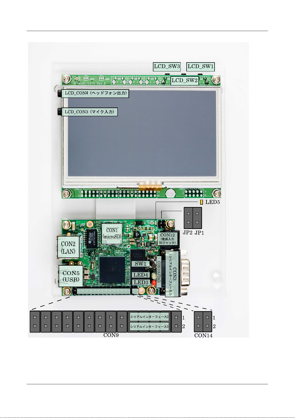
3.1. Layout Diagram
The layout diagram of the Armadillo-440 is shown below. Please make sure to confirm the position of each interface.
15
Page 16
Armadillo-440 LCD Model Development Set Startup Guide
Before Getting Started
Figure 3.1. Layout Diagram
16
Page 17
Armadillo-440 LCD Model Development Set Startup Guide Before Getting Started
Serial Interfaces 2 and 3 have +3.3V I/O levels. They can be used at RS232C levels
by connecting the RS232C level conversion adapter included in the Development
Set.
When using the RS232C level conversion adapter, please connect pin 1 (the yellow
or green wire) to CON9 1 for Serial Interface 2 and to CON9 2 for Serial Interface
3.
3.2. Preparation
Please prepare the following items before using the Armadillo.
Work PC and Serial Cross Cable A PC that runs either Linux or Windows and has at least one serial port, and a D-
Sub 9 pin (female-to-female) serial cross connection cable. Please install a serial
console program
directory on the included DVD).
Network Environment Please connect the Armadillo and Work PC so that they can communicate via a
network.
[1]
on the work PC (software for Linux is contained in the tool
3.3. Connections
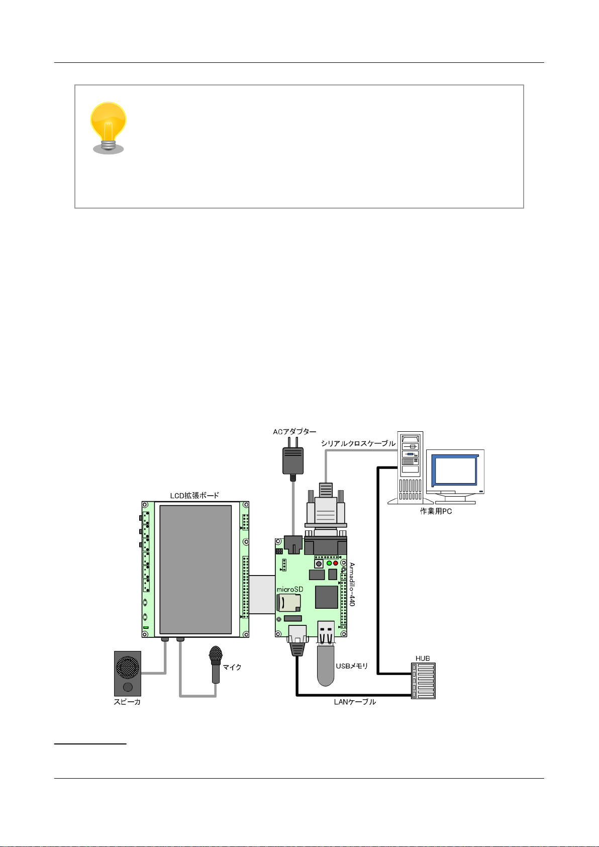
The following is an example of the Armadillo fully connected.
Figure 3.2. Connection Diagram
[1]
For example, "minicom" for Linux and "Tera Term" for Windows.
17
Page 18
Armadillo-440 LCD Model Development Set Startup Guide Before Getting Started
3.3.1. microSD Insertion
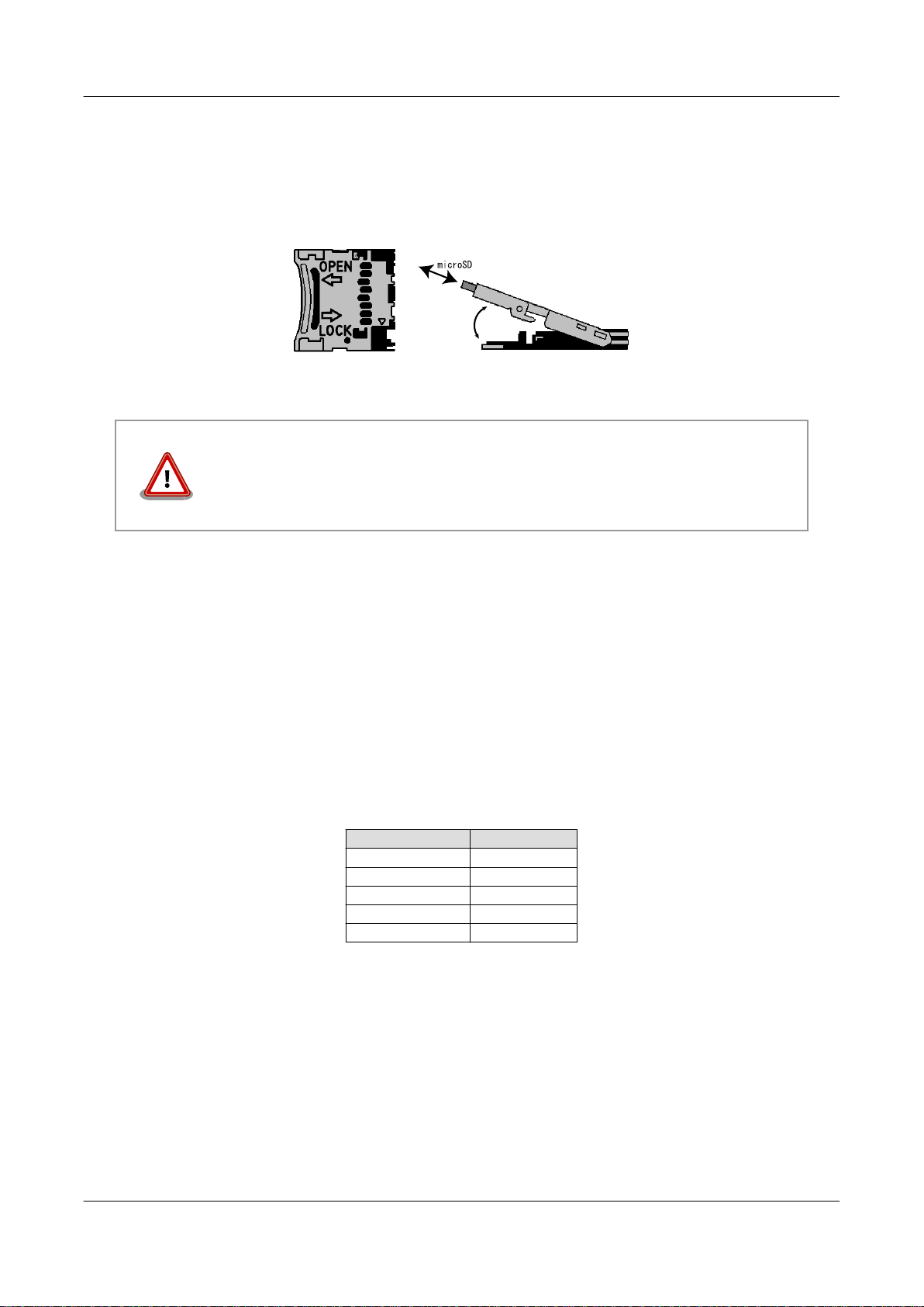
CON1 is a hinge type connector. The cover on the connector must be opened in order to insert and remove the card. When
opening, the cover should first be unlocked by sliding the upper part of the connector horizontally in the direction shown
by the OPEN arrow.
Figure 3.3. microSD Insertion Diagram
Please be aware that the connector may be damaged if excessive force is applied.
3.4. Jumper Pin Configuration
There will be no need to change jumper pins other than JP2 in this document. Please leave JP1 in an open state. It will
be noted when any change to JP2 is required. Set it to an open state now.
The position of the jumper pins can be seen in Figure 3.1, “Layout Diagram”.
3.5. Serial Console Software Configuration
Start the serial console program and configure the connection as shown in Table 3.1, “Serial Communication Configuration”. Also, please keep the width of the serial communication software to more than 80 characters. The display may
become disordered when entering commands if the width is less than 80 characters.
Table 3.1. Serial Communication Configuration
Item Configuration
Transmission Rate 115,200bps
Data Length 8bit
Stop Bit 1bit
Parity None
Flow Control None
18
Page 19

Armadillo-440 LCD Model Development Set Startup Guide
Startup and Shutdown
Chapter 4. Startup and Shutdown
4.1. Startup
Connect the power supply to the Armadillo. The boot log shown below will be displayed in the serial console program.
Hermit-At v2.0.0 (armadillo4x0) compiled at 23:03:08, Mar 08 2010
Uncompressing ⏎
kernel........................................................................... ⏎
..............................done.
Uncompressing ⏎
ramdisk.......................................................................... ⏎
................................................................................. ⏎
................................................................................. ⏎
................................................................................. ⏎
................................................................................. ⏎
................................................................................. ⏎
................................................................................. ⏎
................................................................................. ⏎
................................................................................. ⏎
................................................................................. ⏎
...................................done.
Linux version 2.6.26-at7 (2.6.26) (atmark@atde3) (gcc version 4.3.2 (Debian ⏎
4.3.2-1.1) ) #2 PREEMPT Wed Mar 10 16:50:52 JST 2010
CPU: ARM926EJ-S [41069264] revision 4 (ARMv5TEJ), cr=00053177
Machine: Armadillo-440
Memory policy: ECC disabled, Data cache writeback
CPU0: D VIVT write-back cache
CPU0: I cache: 16384 bytes, associativity 4, 32 byte lines, 128 sets
CPU0: D cache: 16384 bytes, associativity 4, 32 byte lines, 128 sets
Built 1 zonelists in Zone order, mobility grouping on. Total pages: 32512
Kernel command line: console=ttymxc1,115200
MXC IRQ initialized
PID hash table entries: 512 (order: 9, 2048 bytes)
MXC GPT timer initialized, rate = 12000000
Console: colour dummy device 80x30
Dentry cache hash table entries: 16384 (order: 4, 65536 bytes)
Inode-cache hash table entries: 8192 (order: 3, 32768 bytes)
Memory: 128MB = 128MB total
Memory: 99596KB available (3096K code, 207K data, 128K init)
Mount-cache hash table entries: 512
CPU: Testing write buffer coherency: ok
net_namespace: 480 bytes
NET: Registered protocol family 16
MXC WDOG1 Enabled
CPU is i.MX25 Revision 1.0
Clock input source is 24000000
MXC GPIO hardware
Using SDMA I.API
MXC DMA API initialized
SCSI subsystem initialized
usbcore: registered new interface driver usbfs
usbcore: registered new interface driver hub
19
Page 20

Armadillo-440 LCD Model Development Set Startup Guide
Startup and Shutdown
usbcore: registered new device driver usb
MXC I2C driver
MXC I2C driver
MC34704 regulator successfully probed
mc34704 0-0054: Loaded
NET: Registered protocol family 2
IP route cache hash table entries: 1024 (order: 0, 4096 bytes)
TCP established hash table entries: 4096 (order: 3, 32768 bytes)
TCP bind hash table entries: 4096 (order: 2, 16384 bytes)
TCP: Hash tables configured (established 4096 bind 4096)
TCP reno registered
NET: Registered protocol family 1
checking if image is initramfs...it isn't (bad gzip magic numbers); looks like an ⏎
initrd
Freeing initrd memory: 26797K
usb: Host 2 host (serial) registered
usb: DR host (utmi) registered
NetWinder Floating Point Emulator V0.97 (double precision)
msgmni has been set to 247
io scheduler noop registered
io scheduler cfq registered (default)
mx2fb: Unable to set clock to 0
Console: switching to colour frame buffer device 60x17
mxc_sdc_fb mxc_sdc_fb.0: fb0: DISP0 BG fb device registered successfully.
mxc_sdc_fb mxc_sdc_fb.0: fb1: DISP0 FG fb device registered successfully.
Serial: MXC Internal UART driver
mxcintuart.1: ttymxc1 at MMIO 0x43f94000 (irq = 32) is a Freescale MXC
console [ttymxc1] enabled
mxcintuart.2: ttymxc2 at MMIO 0x5000c000 (irq = 18) is a Freescale MXC
mxcintuart.4: ttymxc4 at MMIO 0x5002c000 (irq = 40) is a Freescale MXC
brd: module loaded
loop: module loaded
FEC Ethernet Driver
PPP generic driver version 2.4.2
Driver 'sd' needs updating - please use bus_type methods
armadillo-nor: Found 1 x16 devices at 0x0 in 16-bit bank
Intel/Sharp Extended Query Table at 0x010A
Intel/Sharp Extended Query Table at 0x010A
Intel/Sharp Extended Query Table at 0x010A
Intel/Sharp Extended Query Table at 0x010A
Intel/Sharp Extended Query Table at 0x010A
Using buffer write method
Using auto-unlock on power-up/resume
cfi_cmdset_0001: Erase suspend on write enabled
armadillo-nor: use default partitions(4)
Creating 4 MTD partitions on "armadillo-nor":
0x00000000-0x00020000 : "nor.bootloader"
0x00020000-0x00220000 : "nor.kernel"
0x00220000-0x01fe0000 : "nor.userland"
0x01fe0000-0x02000000 : "nor.config"
fsl-ehci fsl-ehci.0: Freescale On-Chip EHCI Host Controller
fsl-ehci fsl-ehci.0: new USB bus registered, assigned bus number 1
fsl-ehci fsl-ehci.0: irq 35, io mem 0x53ff4400
fsl-ehci fsl-ehci.0: USB 2.0 started, EHCI 1.00, driver 10 Dec 2004
usb usb1: configuration #1 chosen from 1 choice
hub 1-0:1.0: USB hub found
hub 1-0:1.0: 1 port detected
fsl-ehci fsl-ehci.1: Freescale On-Chip EHCI Host Controller
20
Page 21

Armadillo-440 LCD Model Development Set Startup Guide
Startup and Shutdown
fsl-ehci fsl-ehci.1: new USB bus registered, assigned bus number 2
fsl-ehci fsl-ehci.1: irq 37, io mem 0x53ff4000
fsl-ehci fsl-ehci.1: USB 2.0 started, EHCI 1.00, driver 10 Dec 2004
usb usb2: configuration #1 chosen from 1 choice
hub 2-0:1.0: USB hub found
hub 2-0:1.0: 1 port detected
Initializing USB Mass Storage driver...
usbcore: registered new interface driver usb-storage
USB Mass Storage support registered.
input: gpio-keys as /devices/platform/gpio-keys.0/input/input0
rtc-s353xxa 2-0030: rtc core: registered rtc-s353xxa as rtc0
rtc-s353xxa: S-353XXA Real Time Clock class driver, (C) 2008 Atmark Techno, ⏎
Inc.i2c /dev entries driver
mxsdhci: MXC Secure Digital Host Controller Interface driver
mxsdhci: MXC SDHCI Controller Driver.
mmc0: SDHCI detect irq 159 irq 9 INTERNAL DMA
Registered led device: red
Registered led device: green
Registered led device: yellow
usbcore: registered new interface driver usbhid
usbhid: v2.6:USB HID core driver
i.MX ADC at 0x50030000 irq 46
Advanced Linux Sound Architecture Driver Version 1.0.16.
ASoC version 0.13.2
wm8978: WM8978 Audio Codec v0.2
asoc: WM8978 HiFi <-> imx-i2s-1 mapping ok
ALSA device list:
#0: armadillo440 (WM8978)
ip_tables: (C) 2000-2006 Netfilter Core Team
TCP cubic registered
NET: Registered protocol family 17
NET: Registered protocol family 15
Static Power Management for Freescale i.MX25
input: imx_adc_ts as /devices/virtual/input/input1
i.MX ADC input touchscreen loaded.
rtc-s353xxa 2-0030: setting system clock to 2000-01-01 00:54:26 UTC (946688066)
RAMDISK: ext2 filesystem found at block 0
RAMDISK: Loading 26797KiB [1 disk] into ram disk... done.
VFS: Mounted root (ext2 filesystem).
Freeing init memory: 128K
mmc0: new high speed SD card at address 0007
mmcblk0: mmc0:0007 SD01G 995328KiB
mmcblk0: p1 p2
init started: BusyBox v1.00 (2010.03.09-06:07+0000) multi-call binary
Starting fsck for root filesystem.
fsck 1.25 (20-Sep-2001)
ext2fs_check_if_mount: No such file or directory while determining whether /dev/ ⏎
ram0 is mounted.
/dev/ram0: clean, 1039/1248 files, 24153/26797 blocks
Checking root filesystem: done
Remounting root rw: done
Mounting proc: done
Mounting usbfs: done
Mounting sysfs: done
Cleaning up system: done
Running local start scripts.
Starting udevd: done
Loading /etc/config: done
21
Page 22

Armadillo-440 LCD Model Development Set Startup Guide
Changing file permissions: done
Configure /home/ftp: done
Starting syslogd: done
Starting klogd: done
Starting basic firewall: done
Setting hostname: done
Configuring network interfaces: udhcpc (v0.9.9-pre) started
fec: PHY @ 0x0, ID 0x0007c0f1 -- LAN8720
Sending discover...
eth0: link down
eth0: link up, 100Mbps, full-duplex
Sending discover...
Sending select for 172.16.2.154...
Lease of 172.16.2.154 obtained, lease time 86400
done
Starting inetd: done
Setting at-cgi: done
Starting lighttpd: done
Creating avahi.services: done
Starting avahi.daemon: done
Starting Xfbdev: done
Mounting ramfs /home/ftp/pub: done
Running local start script (/etc/config/rc.local).
Starting functester: done
Startup and Shutdown
atmark-dist v1.25.0 (AtmarkTechno/Armadillo-440)
Linux 2.6.26-at7 [armv5tejl arch]
armadillo440-0 login:
Figure 4.1. Boot Log
4.2. Login
The login prompt will be displayed once the boot has completed. The usernames shown in Table 4.1, “Serial Console
Login Username and Password” can be used to login.
Table 4.1. Serial Console Login Username and Password
Username Password Permissions
root root root user
guest None general user
4.3. Shutdown Method
To perform a safe shutdown, execute the command shown below, wait until the "The system is halted." message is
displayed and then disconnect the power supply.
22
Page 23
Armadillo-440 LCD Model Development Set Startup Guide Startup and Shutdown
[armadillo ~]# halt
[armadillo ~]#
System is going down for system reboot now.
Starting local stop scripts.
Exiting Syslogd!
Syncing all filesystems: done
Unmounting all filesystems: done
The system is going down NOW !!
Sending SIGTERM to all processes.
The system is halted. Press Reset or turn off power
Figure 4.2. Shutdown Method
When not using removable storage, it is possible to perform a shutdown by just disconnecting the power supply.
Disconnecting the power supply while data is being written to removable storage
may result in the filesystem or the data being damaged. Be sure to unmount removable storage first before disconnecting the power supply.
23
Page 24
Armadillo-440 LCD Model Development Set Startup Guide
Function Tests
Chapter 5. Function Tests
This chapter explains how to perform a hardware operation check using the function test application included in the
default userland of the Armadillo-440 LCD Model. The function test application is automatically displayed on the LCD
panel after the Armadillo-440 LCD Model is powered on. Please go through all tests in this chapter after obtaining the
Armadillo-440 LCD Model in order confirm that the hardware is operating correctly.
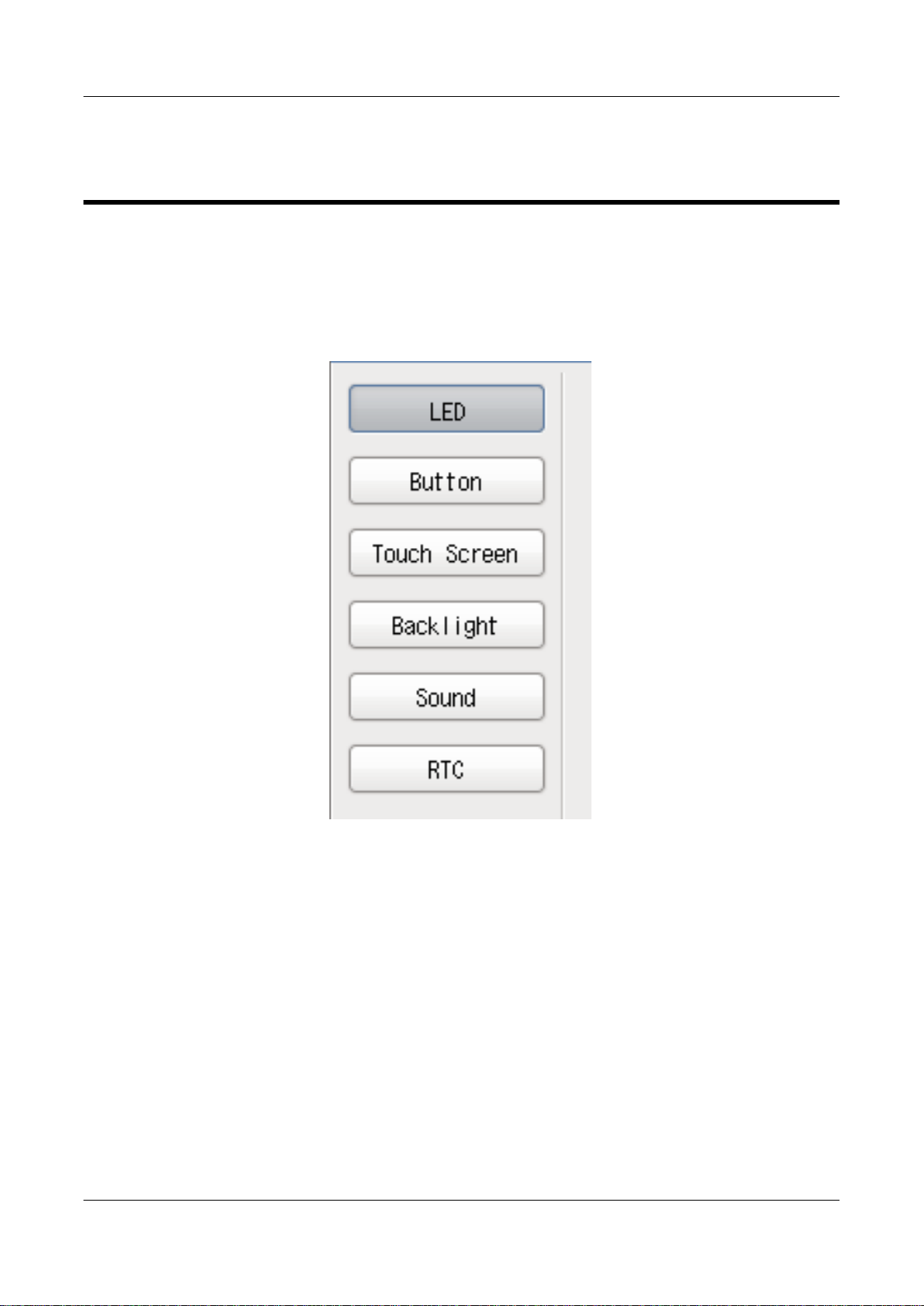
The tests can be selected by pressing the buttons on the left side of the screen.
Figure 5.1. Function Tests - Menu
5.1. LED
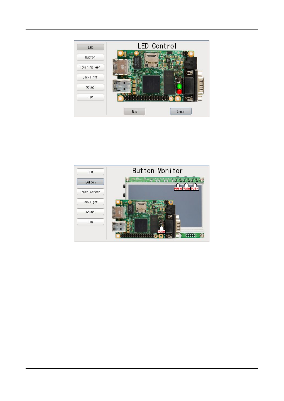
This tests whether or not the LEDs can be turned on and off. Press the "Red" and "Green" buttons and check that the
actual LEDs on the Armadillo-440 are in the same state as that shown on the screen.
24
Page 25
Armadillo-440 LCD Model Development Set Startup Guide
Function Tests
Figure 5.2. Function Tests - LEDs
5.2. Buttons
This tests whether or not the state of the buttons can be obtained. Press each button on the Armadillo-440 and the
Armadillo-400 Series LCD Expansion Board and check that "Push" is displayed in the correct position on the screen.
Figure 5.3. Function Tests - Buttons
5.3. Touch Screen
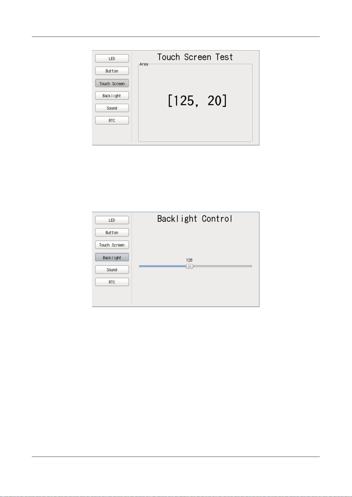
This tests whether or not the touch screen coordinates can be obtained. The touch screen coordinates are displayed as [X,
Y]. Check that the X value increases with touches further to the right and the Y value increases with touches further to the
bottom.
25
Page 26
Armadillo-440 LCD Model Development Set Startup Guide
Function Tests
Figure 5.4. Function Tests - Touch Screen
5.4. Backlight
This tests whether or not the brightness of the backlight on the LCD panel can be adjusted. The backlight brightness is
adjusted with the slider. Check that moving the slider to the left darkens the backlight and moving it to the right brightens
the blacklight.
Figure 5.5. Function Tests - Backlight
5.5. Sound
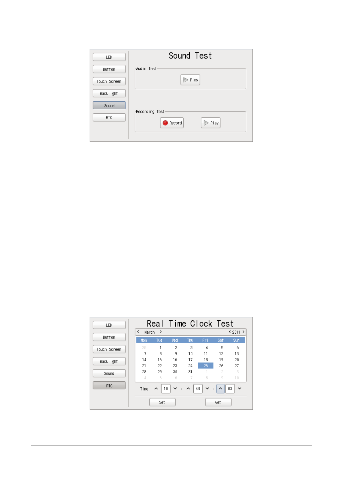
This tests whether or not sound can be recorded and played back. Be sure to refer to Figure 3.2, “Connection Diagram”
to connect a speaker and microphone before carrying out the test.
26
Page 27
Armadillo-440 LCD Model Development Set Startup Guide
Figure 5.6. Function Tests - Sound
5.5.1. Playing Back Sound
Check that a sound can be heard after pressing the "Play" button in "Audio Test."
Function Tests
5.5.2. Recording Sound
Press the "Record" button in "Recording Test" to record sound with the microphone. After recording for approximately
five seconds, the "Record" button will return to its initial state.
Next, press the "Play" button in "Recording Test" and check that the recorded sound can be heard.
5.6. RTC (Real-Time Clock)
This tests whether or not time configuration can be written to and read from the RTC.
Enter a date and time on the calendar and then press the "Set" button to set the system clock and RTC (hardware clock).
Press the "Get" button to read the date and time from the RTC (hardware clock) and display it on the calendar. Please
note that the hardware clock and system clock will not always match.
Figure 5.7. Function Tests - RTC
27
Page 28
Armadillo-440 LCD Model Development Set Startup Guide Function Tests
5.7. Stopping the Function Test Application from Starting
After having completed all of the function tests, if you wish to stop the function test application from starting automatically,
execute the commands shown in Figure 5.8, “Stopping Automatic Startup”
[armadillo ~]# chmod -x /etc/config/rc.local
[armadillo ~]# flatfsd -s
Figure 5.8. Stopping Automatic Startup
To have the function test application start automatically again, execute the commands shown in Figure 5.9, “Starting
Automatic Startup”.
[armadillo ~]# chmod +x /etc/config/rc.local
[armadillo ~]# flatfsd -s
Figure 5.9. Starting Automatic Startup
28
Page 29

Armadillo-440 LCD Model Development Set Startup Guide
Network
Chapter 6. Network
This chapter explains the default network configuration and how to change this configuration, and also explains how to
use the included network applications.
6.1. Default Network Connection Mechanisms
In its default state, the Armadillo is configured to have an IP address assigned to it automatically with either DHCP or
Zeroconf so that it can connect to the network. The PC side network connection must also be configured so that it too
correctly connects to the same network as the Armadillo.
6.1.1. DHCP Connections
When the Armadillo automatically connects to the network, it first attempts to use DHCP. When a DHCP server is present
on the network, an IP address is assigned to the Armadillo in accordance with the response from the DHCP server.
If the PC also uses DHCP in the same way, it will by default connect to the same network as the Armadillo.
6.1.2. Zeroconf Connections
If no DHCP server is found, the Armadillo uses a mechanism called Zeroconf (IPv4LL) to assign an IP address.
To connect with an Armadillo configured this way, the PC must connect to the same network. If Zeroconf is also used
on the PC side, it of course can do so without problem.
Note: Zeroconf is called Automatic Private IP Addressing (APIPA) in Windows. Zeroconf uses an address from a specific
range (169.254.0.1 - 169.254.255.254) with a subnet mask of 255.255.0.0. This IP address block is reserved by IANA
(Internet Assigned Numbers Authority).
It is also possible to connect to a Zeroconf network by configuring a static IP address. The PC can connect to the same
network by using an IP address from the 169.254.0.1 - 169.254.255.254 range with a subnet mask of 255.255.0.0.
While it is possible that a static IP address selected at random will overlap with the one selected by the Armadillo, this
will not be a problem. As the Zeroconf on the Armadillo will detect transmission from another host using the same IP address
and quickly change its own IP address, the Armadillo and PC will be able to differentiate each other after a brief period of
time.
6.2. Changing Network Configuration
The following explains how to change the network settings on the Armadillo.
Please consult a network administrator for help with network connections.
6.2.1. Using a Web Browser to Change Network Configuration
It is possible to change the various network options using a Web browser. Refer to Section 6.4.7.4.2, “AT Admin: System
- Network” for information on how to make the changes.
29
Page 30

Armadillo-440 LCD Model Development Set Startup Guide
Network
6.2.2. Logging In to Change Network Configuration
Boot-time network configuration can be changed by editing the appropriate file under /etc/config and saving it to
the config region. Refer to Chapter 12, Config Region - Configuration File Storage for details on saving to the config region.
6.2.2.1. Using a Static Address
In order to set the options shown in Table 6.1, “Static IP Address Configuration Example”, use the vi editor to change
the content of the /etc/config/interfaces file in the same way as shown in Figure 6.1, “Static IP Address Configuration”.
Table 6.1. Static IP Address Configuration Example
Item Configuration
IP Address 192.168.10.10
Netmask 255.255.255.0
Network Address 192.168.10.0
Broadcast Address 192.168.10.255
Default Gateway 192.168.10.1
[armadillo ~]# vi /etc/config/interfaces
# /etc/network/interfaces -- configuration file for ifup(8), ifdown(8) auto lo ⏎
eth0 iface lo inet loopback
iface eth0 inet static address 192.168.10.10 netmask 255.255.255.0 network ⏎
192.168.10.0 broadcast 192.168.10.255 gateway 192.168.10.1
Figure 6.1. Static IP Address Configuration
6.2.2.2. Using DHCP
In order to use DHCP, use the vi editor to change the content of the /etc/config/interfaces file in the same
way as shown in Figure 6.2, “DHCP Configuration”.
[armadillo ~]# vi /etc/config/interfaces# /etc/network/interfaces -- configuration ⏎
file for ifup(8), ifdown(8) auto lo eth0 iface lo inet loopback
iface eth0 inet dhcp
Figure 6.2. DHCP Configuration
6.2.2.3. Specifying A DNS Server
To specify a DNS server, use the vi editor to edit /etc/config/resolv.conf.
[armadillo ~]# vi /etc/config/resolv.conf
nameserver 192.168.10.1
Figure 6.3. DNS Server Configuration
6.2.3. Checking the Connection
The following shows how to check whether or not transmission is possible with the changed IP configuration.
30
Page 31
Armadillo-440 LCD Model Development Set Startup Guide
First, enable the new configuration. This is not required if the settings were saved to the config region and the system
rebooted.
[armadillo ~]# ifdown -a
[armadillo ~]# ifup -a
Figure 6.4. Enabling Configuration
Use ping to try to communicate with another host on the same network.
[armadillo ~]# ping 192.168.10.1
Figure 6.5. Ping Confirmation
6.3. Firewall
A simple firewall is enabled on the Armadillo. To display the current configuration, execute the command shown in
Figure 6.6, “iptables”.
Network
[armadillo ~]# iptables --list
Figure 6.6. iptables
6.4. Network Applications
The following explains how to operate the network related applications included in the factory default userland.
6.4.1. Telnet
6.4.1.1. Telnet Server
It is possible to login from another PC via the network and perform remote operations. The username shown in Table 6.2,
“Username for Telnet Login” can be used to login.
Table 6.2. Username for Telnet Login
Username Password
guest None
6.4.1.2. Telnet Client
Telnet can be used to remotely login to another PC. To use telnet, execute the command as shown in Figure 6.7, “telnet”.
[armadillo ~]# telnet [TELNET SERVER]
Figure 6.7. telnet
31
Page 32
Armadillo-440 LCD Model Development Set Startup Guide
6.4.2. FTP
6.4.2.1. FTP Server
File transfers can be performed from another PC via the network. The username shown in Table 6.3, “Username for FTP
Login” can be used to login.
Table 6.3. Username for FTP Login
Username Password
ftp None
6.4.2.2. FTP Client
ftp can be used to transfer files with another PC. To use ftp, execute the command as shown in Figure 6.8, “ftp”.
[armadillo ~]# ftp [FTP SERVER]
Figure 6.8. ftp
Network
6.4.3. SSH
6.4.3.1. SSH Server
It is possible to login from another PC via the network and safely perform remote operations. The ssh server is set to not
start automatically at boot time. To start the ssh server, execute the command as shown in Figure 6.9, “Starting sshd”.
[armadillo ~]# sh /etc/init.d/sshd
Figure 6.9. Starting sshd
A public key is required in order to use sshd. This key will be generated automatically if it does not exist, a process which takes a number of minutes to perform.
For the username that can be used for login, refer to Table 6.4, “Username for ssh Login”.
Table 6.4. Username for ssh Login
Username
guest None
Password
6.4.3.2. SSH Client
ssh can be used to safely login to another PC. To use ssh, execute the command as shown in Figure 6.10, “ssh”.
[armadillo ~]# ssh [USER]@[SSH SERVER]
Figure 6.10. ssh
32
Page 33

Armadillo-440 LCD Model Development Set Startup Guide Network
6.4.4. Web Server
A Web server runs on the Armadillo. The Web server's top page will be displayed when the URL of the Armadillo (http://
[Armadillo's IP address])
[1]
is accessed from a Web browser.
6.4.5. NTP Client
The NTP (Network Time Protocol) client can be used to obtain time information from a time server. Execute the command
as shown in Figure 6.11, “ntpclient”.
[armadillo ~]# ntpclient -h [NTP SERVER] -s
36525 42052.288 32712.0 321.0 320195180072231.5 259.4 0
Figure 6.11. ntpclient
6.4.6. SMTP Client
The SMTP (Simple Mail Transfer Protocol) client can be used to send email. Execute the command shown in Figure 6.12,
“mail”.
[armadillo ~]# echo "[BODY]" | mail --subject="[TITLE]" --from="[FROM]" --smtp- ⏎
host=[SMTP SERVER] [TO]
Figure 6.12. mail
It will not be possible to send email if the current hostname is not specified in the /
etc/hosts file. Execute the following command to check the current configuration.
[armadillo ~]# echo $HOSTNAME
armadillo440-0
[armadillo ~]# cat /etc/hosts
127.0.0.1 localhost
127.0.0.1 armadillo440-0
::1 localhost.v6
[1]
If the Armadillo's IP address is 192.168.10.10, then this will be http://192.168.10.10/.
33
Page 34
Armadillo-440 LCD Model Development Set Startup Guide
6.4.7. at-cgi
It is possible to perform network configuration and firmware management from a Web browser.
6.4.7.1. AT Admin: Admin Screen
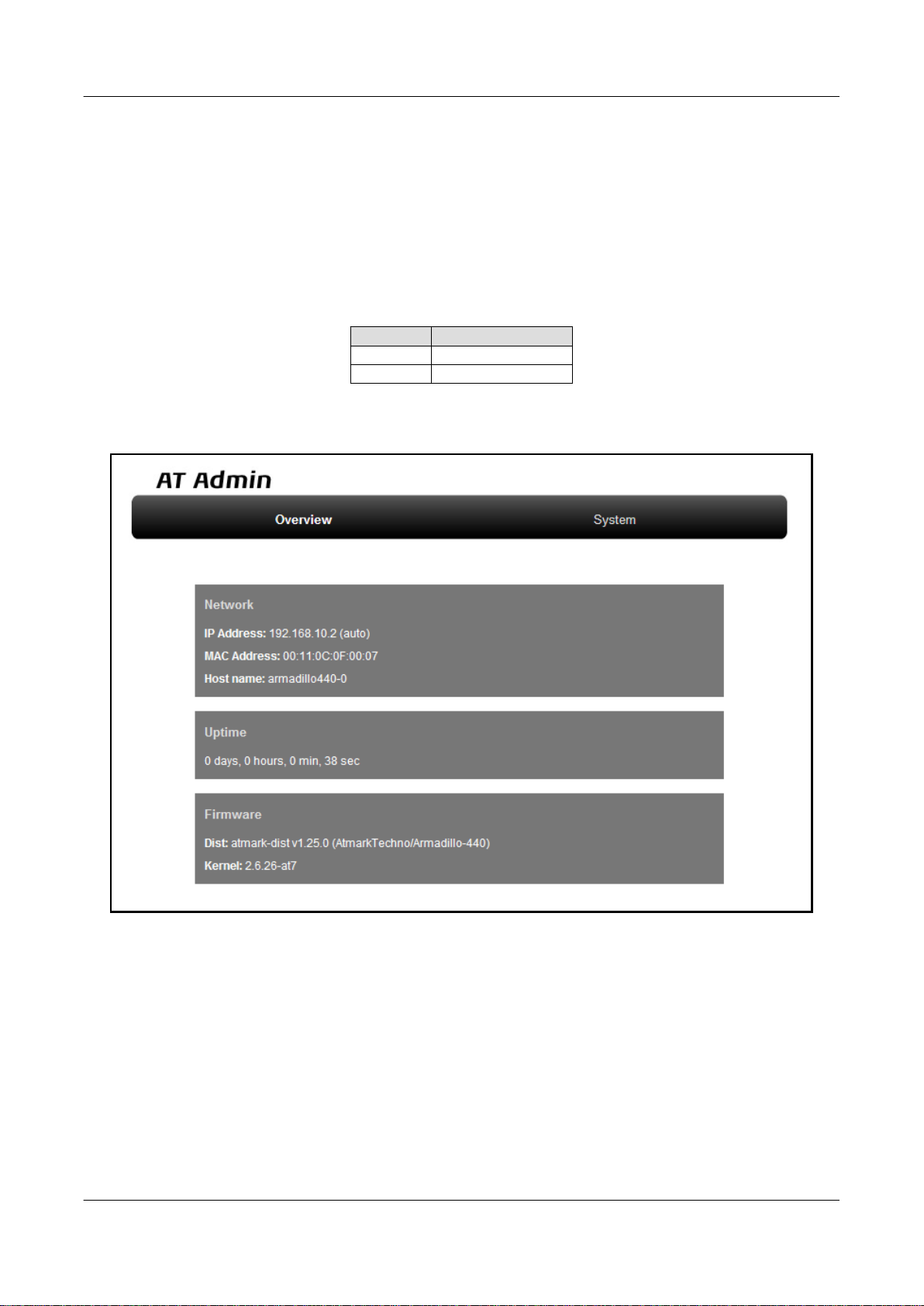
The top page of at-cgi as shown in Figure 6.13, “AT Admin: Overview” will be displayed in the Web browser upon
accessing http://[Armadillo's IP address]/index.cgi.
The top page of at-cgi is AT Admin's "Overview." "Overview" and "System" are available in AT Admin.
Menu Function
Overview System Overview
System System Configuration
These two functions are always displayed in the menu at the top of the page. Each one can be selected by clicking on the
title.
Network
Figure 6.13. AT Admin: Overview
34
Page 35

Armadillo-440 LCD Model Development Set Startup Guide
6.4.7.2. AT Admin: Authorization
Authorization is required upon selecting "System" in AT Admin. A sub-window like that shown in Figure 6.14, “AT
Admin: System Username / Password Authorization” will be displayed at this time.
The default username and password are as shown below.
Username Password
admin admin
Enter the username and password and press the OK button. If authorization is successful, the selected screen will be
displayed.
Network
Figure 6.14. AT Admin: System Username / Password Authorization
35
Page 36

Armadillo-440 LCD Model Development Set Startup Guide
6.4.7.3. AT Admin: Overview
The following explains each part of the Overview screen. Three main groups of information are displayed in the Overview.
• Network
• Uptime
• Firmware
6.4.7.3.1. Network
In Network, a summary of the current network configuration is displayed. The following three items are shown.
IP Address
The current IP address is shown here. When "(auto)" is displayed after the IP address, this indicates that an IP
address has been automatically configured with either DHCP or Zeroconf. When "(static)" is displayed, this indicates
that a static IP address has been set.
MAC Address
The assigned unique MAC address is shown here.
Host name
Network
The configured hostname is shown here. This is armadillo440-0 by default.
6.4.7.3.2. Uptime
The time that has past since the Armadillo was booted is shown here. It is displayed as: days, hours, min, sec.
6.4.7.3.3. Firmware
The current firmware is displayed here.
Dist
The version and profile name of the distribution is shown here.
Kernel
The version of the Linux kernel is shown here.
36
Page 37
Armadillo-440 LCD Model Development Set Startup Guide
6.4.7.4. AT Admin: System
6.4.7.4.1. AT Admin: System - System Overview
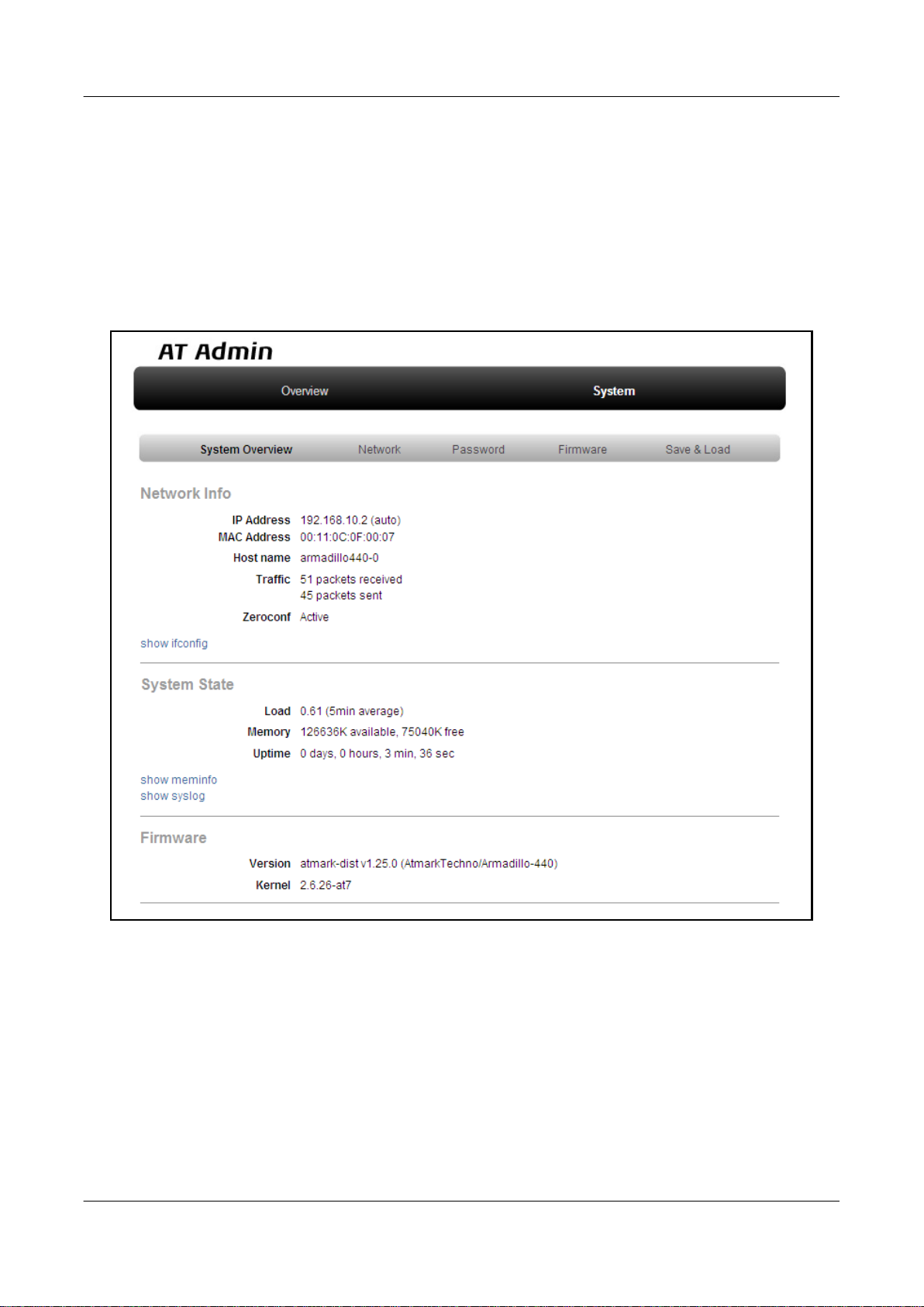
Configuration information related to the Armadillo can be checked on the System Overview. Three main groups of
information are displayed here.
• Network Info
• System State
• Firmware
Network
Figure 6.15. AT Admin: System - System Overview
37
Page 38

Armadillo-440 LCD Model Development Set Startup Guide
6.4.7.4.1.1. Network Info
Network configuration details are shown in Network Info.
IP Address
The current IP address is shown here. The meaning of the text displayed after the IP address is as shown below.
Text Meaning
(auto) Automatic IP address configuration with either DHCP or Zeroconf
(static) Static IP address configuration
MAC Address
The unique MAC address assigned to the Armadillo is shown here.
Host name
The configured hostname is shown here. This is armadillo440-0 by default.
Traffic
Network
The number of packets sent and received via the network since the system was booted is shown here.
Zeroconf
Whether Bonjour device detection is enabled or not is shown here.
It is possible to obtain more detailed network information from "show ifconfig." The Show ifconfig page displays the
output of the ifconfig command as is. For details on the display content, refer to the ifconfig manual.
6.4.7.4.1.2. System State
It is possible to check the following three items related to the current system state.
Load
The system load state (Load Average) is shown here.
Memory
Memory usage state is shown here.
Uptime
The time that has past since the Armadillo was booted is shown here.
Also, with "show meminfo" and "show syslog," it is possible to check the state of the meminfo information and system
log file as is.
6.4.7.4.1.3. Firmware
The current firmware is displayed here.
Dist
This is information on the distribution and current profile in use. The version and type of the userland (applications)
software is shown here.
38
Page 39
Armadillo-440 LCD Model Development Set Startup Guide
Kernel
The version of the Linux kernel is shown here.
6.4.7.4.2. AT Admin: System - Network
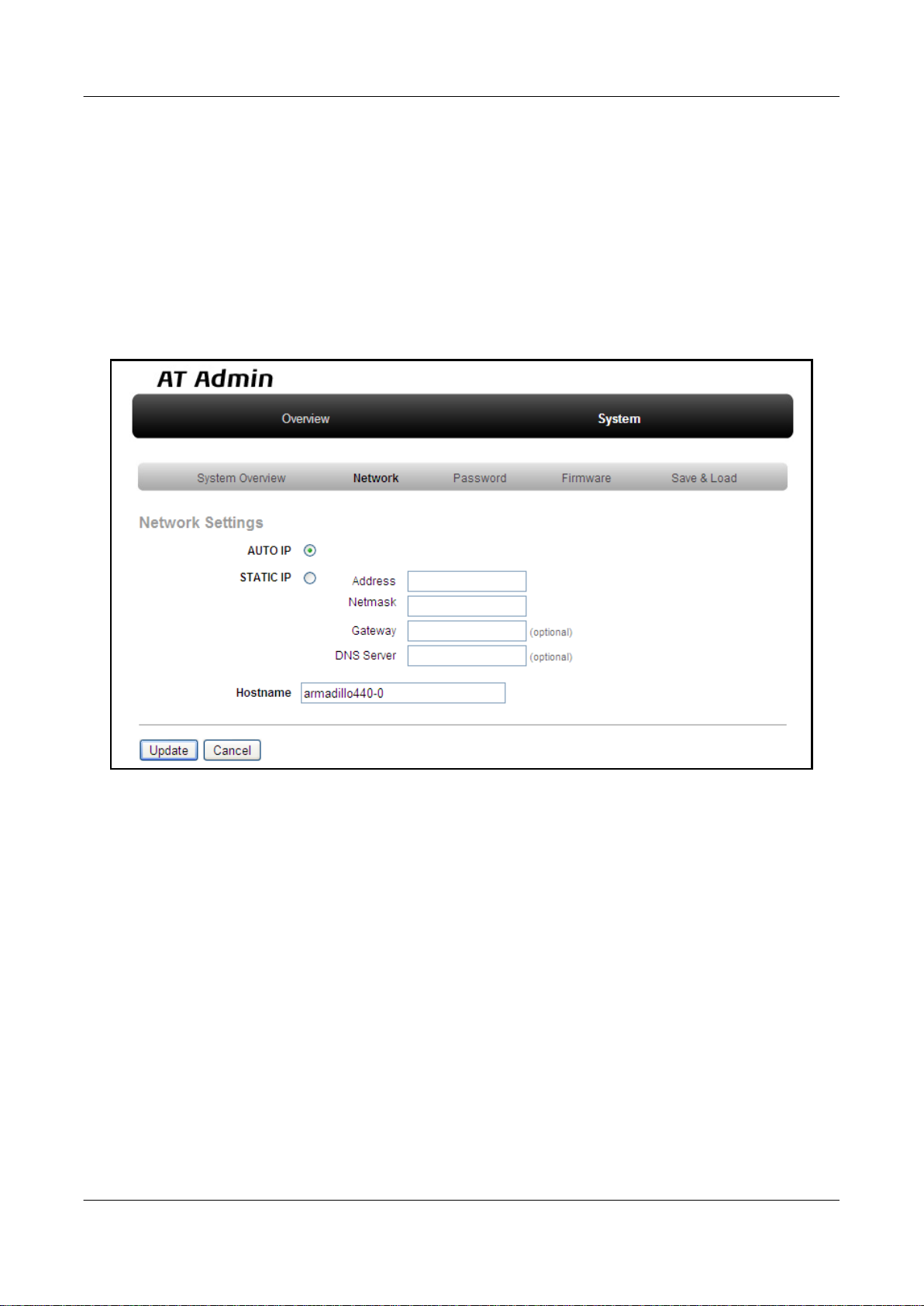
Changes to various network related configuration options can be carried out on the Network screen.
There are two main areas of configuration on the Network screen.
• IP Address
• Hostname
Network
Figure 6.16. AT Admin: System - Network
39
Page 40

Armadillo-440 LCD Model Development Set Startup Guide
6.4.7.4.2.1. IP Address
AUTO IP
Select to have an IP address acquired and set automatically. This is selected by default.
DHCP is used if a DHCP server is found on the network. If a DHCP server is not found, Zeroconf is used to
automatically assign an address. For more details, refer to Chapter 6, Network.
STATIC IP
Select to set a static IP address.
The following details must be configured manually.
Address
Enter the IP address.
Netmask
Enter the subnet mask
Network
Gateway
Enter the IP address of the gateway server. Leave it blank if a gateway is not being used.
DNS Server
Enter the IP address of a DNS (Domain Name System) server. Leave it blank if DNS is not being used.
6.4.7.4.2.2. Hostname
Changes to the hostname are made here. To change the hostname, enter the new name into the textbox. By default, this
is set to "armadillo440-0." With Bonjour, this name is combined with the default network name ".local" to give the Armadillo
the default name of "armadillo440-0.local." This name can be used with a Web browser. For more details, refer to Section 6.5.3, “Bonjour Hostnames”.
40
Page 41
Armadillo-440 LCD Model Development Set Startup Guide
6.4.7.4.2.3. Update
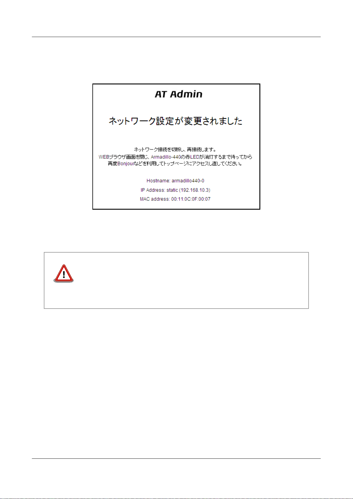
After entering the changes, press the "Update" button and a screen similar to the following will be displayed after which
the Armadillo will begin to operate with the new network configuration.
Network
Figure 6.17. AT Admin: System - Network Update
The red LED on the Armadillo will activate while the network configuration is being updated and deactivate a few seconds
later. After confirming that the LED has deactivated, access the top page on the Armadillo.
Just updating the network configuration does not save the changes.
In order to save the changes so that they remain in effect after the next boot, the
configuration must be saved to flash memory. Refer to Section 6.4.7.4.5, “AT Admin: System - Save & Load” for information on saving.
6.4.7.4.3. AT Admin: System - Password
Changes to the username and password used for authorization of the Packet Scan and System screens can be made on the
Password screen.
41
Page 42
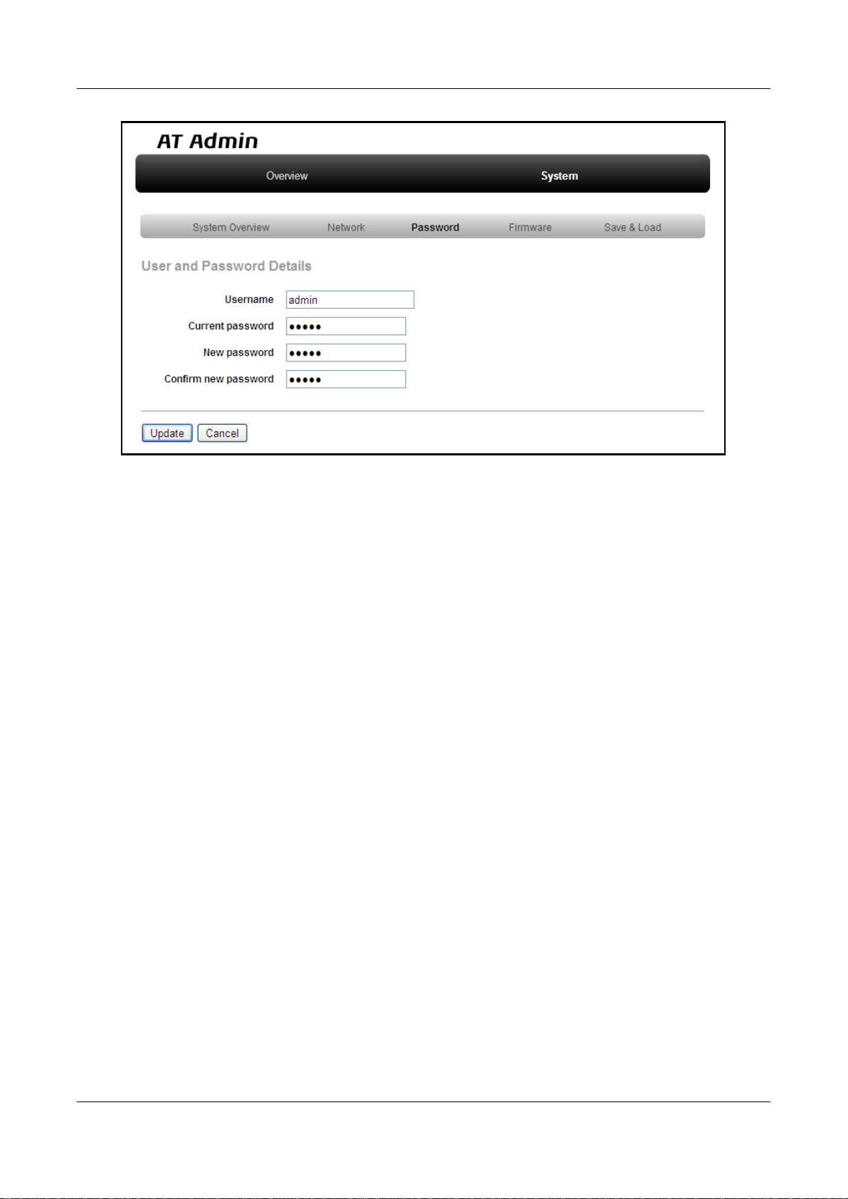
Armadillo-440 LCD Model Development Set Startup Guide
Figure 6.18. AT Admin: System - Password
Network
6.4.7.4.3.1. User and Password Details
Username
Enter the administrator username. This is set to "admin" by default.
Current password
Enter the current password for confirmation. This is set to "admin" by default.
New password
Enter the new password.
Confirm new password
Enter the new password once more for confirmation.
42
Page 43
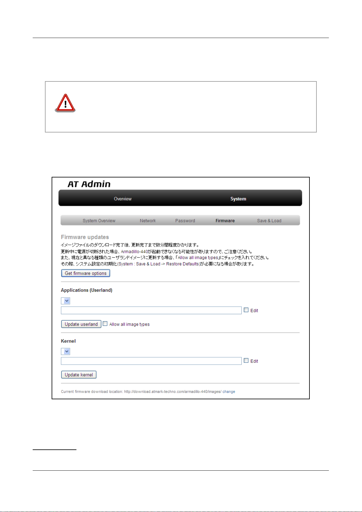
Armadillo-440 LCD Model Development Set Startup Guide Network
6.4.7.4.3.2. Updating Username and Password Configuration
After entering the changes, press the "Update" button to update the configuration.
Just updating the configuration does not save the changes. In order to save the
changes so that they remain in effect after the next boot, the configuration must be
saved to flash memory. Refer to Section 6.4.7.4.5, “AT Admin: System - Save &
Load” for information on saving.
6.4.7.4.4. AT Admin: System - Firmware
The userland (applications) and Linux kernel firmware can be updated on the Firmware screen.
Figure 6.19. AT Admin: System - Firmware
To update to the image files available from the official web site
available image files will be displayed in the "Applications (Userland)" and "Kernel" boxes.
[2]
A connection to the internet is required for this function.
43
[2]
, first press the "Get firmware options" button. The
Page 44
Armadillo-440 LCD Model Development Set Startup Guide
Network
6.4.7.4.4.1. Applications (Userland)
Userland (applications) updates are performed here.
Image Selection Box
Userland images available on the server are shown here. Select the preferred image.
URL Input Box
The URL of the userland image file to be downloaded is displayed here. A URL can be entered directly into this
box by enabling the "Edit" checkbox to the right.
If the "Edit" checkbox is enabled, the path specified in the URL input box
will be used and the image selected in the image selection box ignored.
Press the "Update userland" button and the userland image will be downloaded and written to flash memory. To update
to a userland image model different to that of the current image, enable the "Allow all image types" checkbox before pressing
the "Update userland" button.
6.4.7.4.4.2. Kernel
Linux kernel updates are performed here.
Image Selection Box
Kernel images available on the server are shown here. Select the preferred image.
URL Input Box
The URL of the Linux kernel image file to be downloaded is displayed here. A URL can be entered directly into
this box by enabling the "Edit" checkbox to the right.
If the "Edit" checkbox is enabled, the path specified in the URL input box
will be used and the image selected in the image selection box ignored.
Press the "Update kernel" button and the Linux kernel image will be downloaded and written to flash memory.
44
Page 45
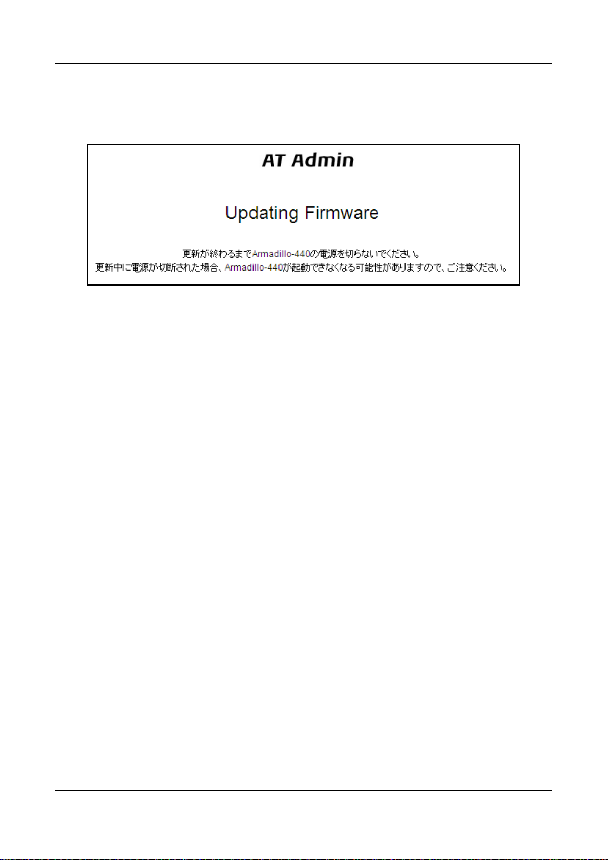
Armadillo-440 LCD Model Development Set Startup Guide
6.4.7.4.4.3. Image Updates
After pressing "Update userland" or "Update kernel," Figure 6.20, “AT Admin: System - Updating Firmware” will be
displayed.
Figure 6.20. AT Admin: System - Updating Firmware
Do not disconnect the Armadillo's power supply while the firmware is being updated. If the power is disconnected before
the update completes, the Armadillo may no longer boot correctly.
Network
Once the update has completed, the Firmware screen shown in Figure 6.19, “AT Admin: System - Firmware” will be
displayed. To update another image, make the necessary selections and press the relevant update button again.
After updating to a different type of firmware the configuration files must be initialized. For information on the initialization of configuration files, refer to Section 6.4.7.4.5, “AT Admin: System - Save & Load”.
After all updates have been completed, reboot the Armadillo to start using the new firmware. Refer to Section 6.4.7.4.5,
“AT Admin: System - Save & Load” for information on rebooting from AT Admin.
45
Page 46
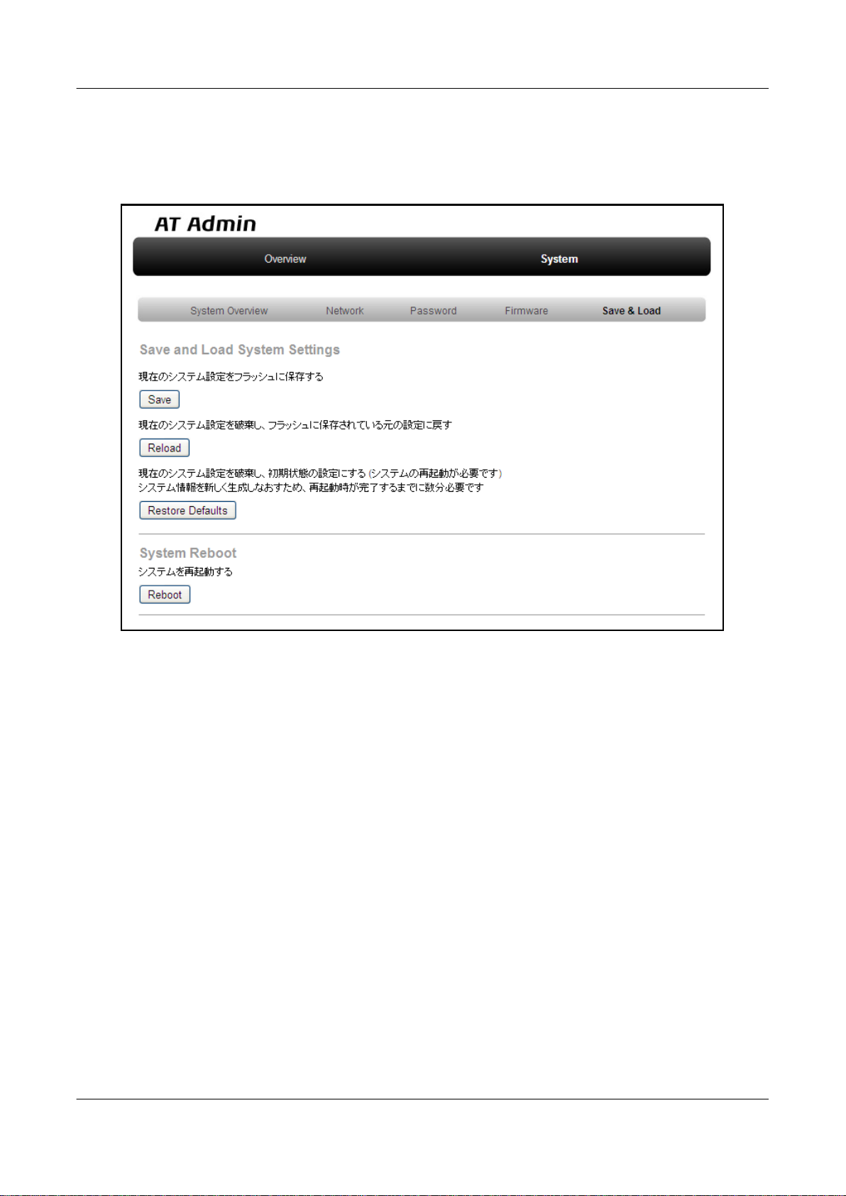
Armadillo-440 LCD Model Development Set Startup Guide
6.4.7.4.5. AT Admin: System - Save & Load
System configuration can be saved to flash memory, reloaded or initialized, and the system rebooted on the Save & Load
screen.
Network
Figure 6.21. AT Admin: System - Save & Load
46
Page 47
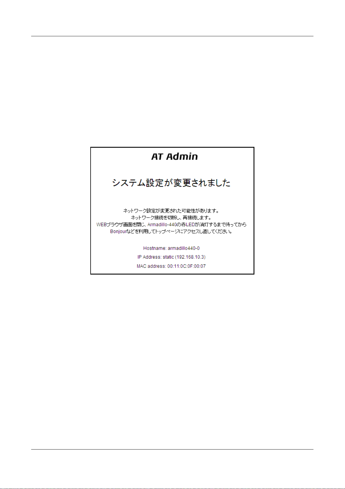
Armadillo-440 LCD Model Development Set Startup Guide
6.4.7.4.5.1. Save & Load System Settings
System configuration can be saved to flash memory or loaded here.
Save current configuration to flash memory (Save)
Save configuration such as that set in "Network Settings" and "Password" to flash memory. The saved configuration
will remain in effect even after the Armadillo is rebooted.
Discard current system configuration and load the configuration saved in flash memory (Reload)
Discard the current configuration and restore the configuration saved in flash memory to return to the previous state.
After a screen similar to that shown below is displayed, the Armadillo will begin to operate with the new (that read
from flash memory) network configuration.
Network
Figure 6.22. AT Admin: System - Reload
If the network connection is changed as a result of restoring the previous configuration, the red LED on the Armadillo
will activate. After confirming that the LED has deactivated, access the top page on the Armadillo.
Discard current system configuration and load the default configuration (Restore Defaults)
Discard the current configuration and restore the default configuration for the currently running firmware. The
configuration saved in flash memory will also be initialized.
47
Page 48
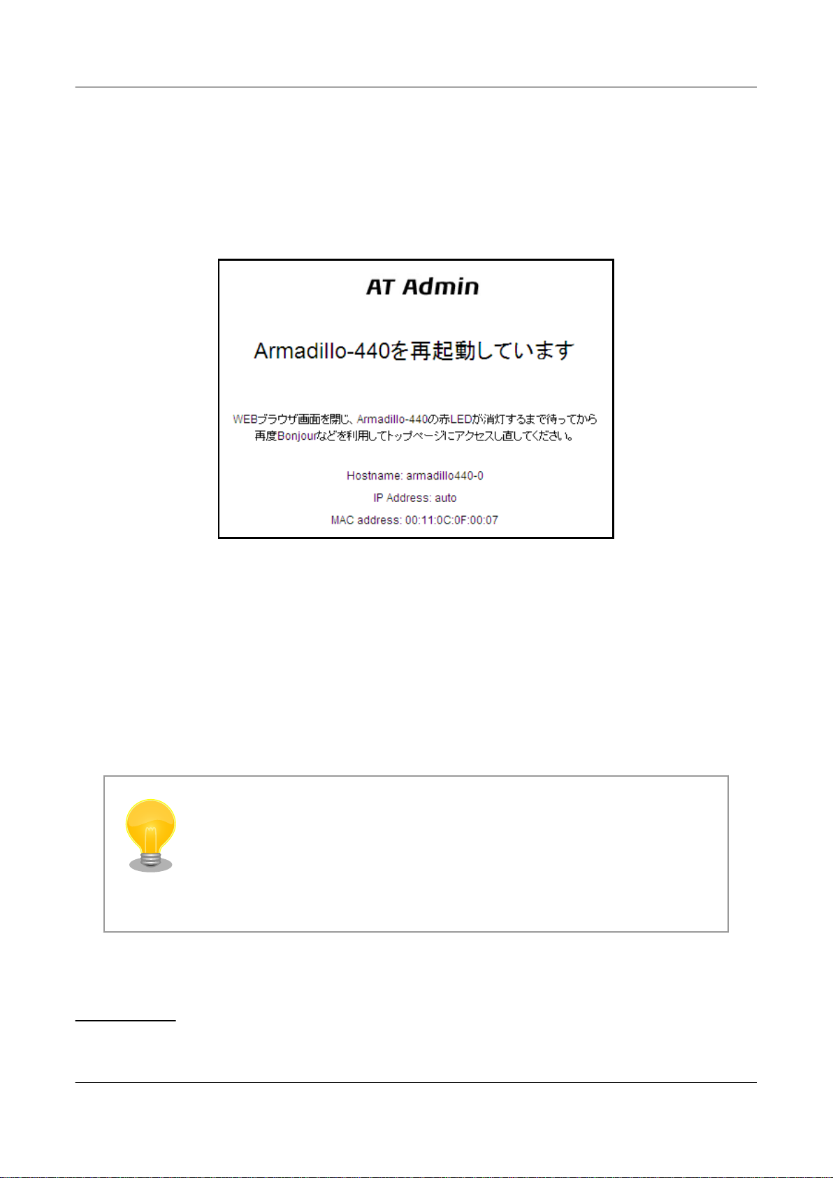
Armadillo-440 LCD Model Development Set Startup Guide Network
6.4.7.4.5.2. System Reboot
The system can be rebooted here.
Reboot the system (Reboot)
This reboots the Armadillo. Approximately 10 seconds after Figure 6.23, “AT Admin: System - Reboot” is displayed, the Armadillo will shutdown and then restart.
Figure 6.23. AT Admin: System - Reboot
After rebooting, if the network connection has changed the red LED on the Armadillo will activate for anywhere between
10 seconds to a number of minutes. After confirming that the LED has deactivated, access the top page on the Armadillo
again.
6.5. Using Bonjour
As Armadillo supports Bonjour, it is possible to easily find an Armadillo from a PC which also supports Bonjour and is
on the same network.
(Quoted from Apple Inc.'s web site)
[3]
About Bonjour
Bonjour, also called zero configuration networking, is a service to automatically
discover computers, devices and services on IP networks. As the world standard IP
protocol is used in Bonjour, devices can automatically detect each other without the
need to enter IP addresses or configure a DNS server.
[3]
The automatic IP address acquisition functionality of the operating system is normally used for the network configuration on the PC side. Refer to
Section 6.1, “Default Network Connection Mechanisms” for more details.
48
Page 49

Armadillo-440 LCD Model Development Set Startup Guide Network
6.5.1. Installing Bonjour
6.5.1.1. Windows
Bonjour for Windows must be installed to use Bonjour on Windows. As third-party distribution of this software is not
permitted, it is not included in the development set. Please download it from Apple Inc.'s web site.
Apple - Support - Downloads - Bonjour for Windows
Execute the downloaded BonjourSetup.exe file and follow the instructions on the screen to install the software.
6.5.1.2. Mac OS X
Bonjour is a standard feature of Max OS X
6.5.1.3. Linux
Bonjour can be used on Linux by utilizing Avahi and the nss-mdns library. Please refer to your distribution's documentation for more information.
49
Page 50
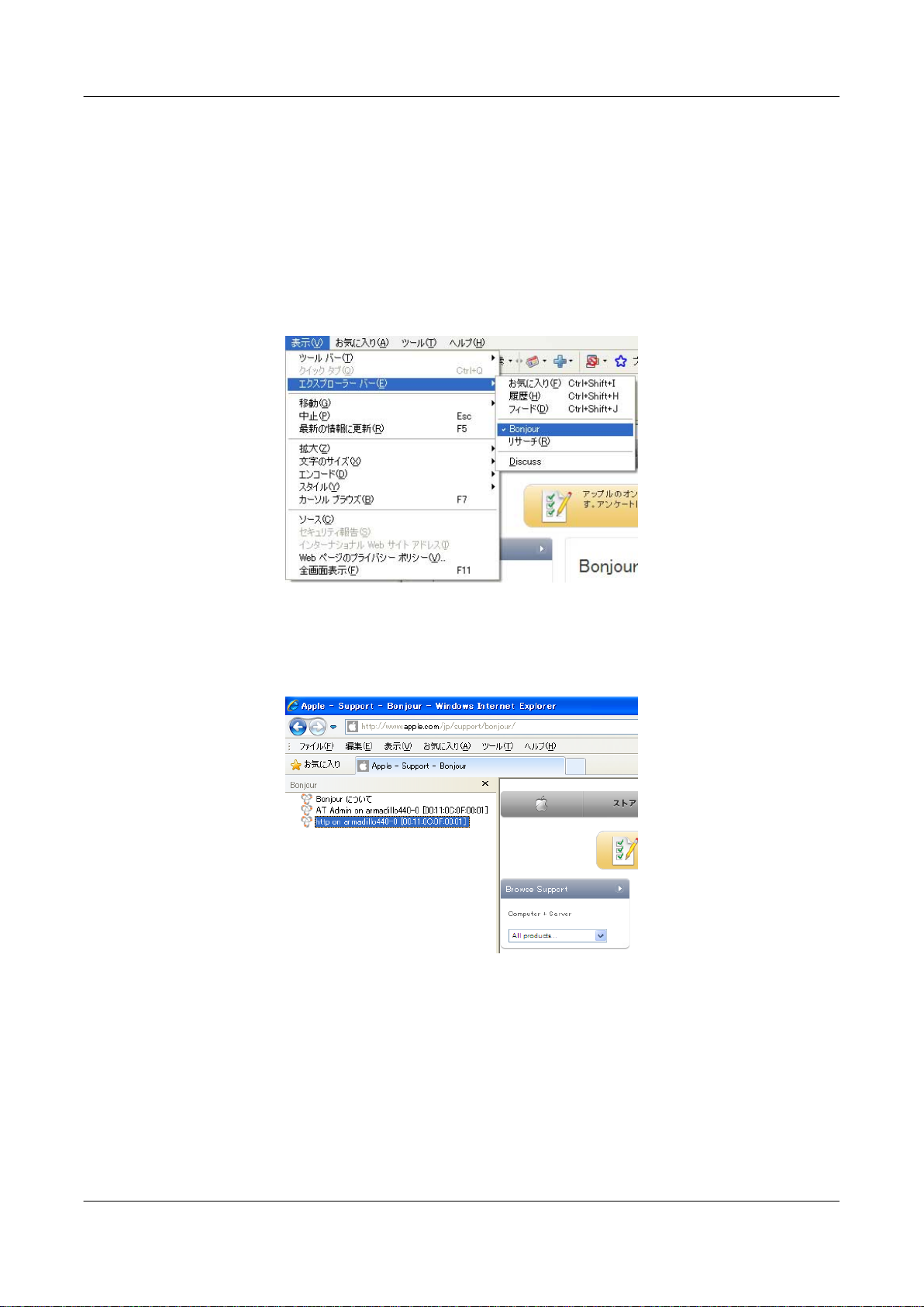
Armadillo-440 LCD Model Development Set Startup Guide
6.5.2. Operational Check
The following demonstrates how to find an Armadillo using Bonjour in a Windows environment. For other operating
systems, please refer to the relevant manuals for that environment.
Start Internet Explorer on the Windows PC.
If Bonjour has been installed, it can be displayed in the Explorer Bar in Internet Explorer (IE). From the menu bar, enable
"View (V)" --> "Explorer Bar (E)" --> "Bonjour."
Network
Figure 6.24. Internet Explorer Explorer Bar Configuration
Check the contents of the "Bonjour" Explorer Bar on the left side of IE.
Figure 6.25. "Bonjour" Explorer Bar
The first line is a link to a description of Bonjour on Apple Inc.'s web site.
Below that, "AT Admin on armadillo440-0 [00:11:0C:XX:XX:XX]" and "http on armadillo440-0
[00:11:0C:XX:XX:XX]" will be displayed. These are links to the Armadillo. Selecting "AT Admin on armadillo440-0
[00:11:0C:XX:XX:XX]" will display the top page of at-cgi in the browser. Refer to Section 6.4.7, “at-cgi” for more details.
Selecting "http on armadillo440 [00:11:0C:XX:XX:XX]" will display the top page of the web server in the browser.
50
Page 51
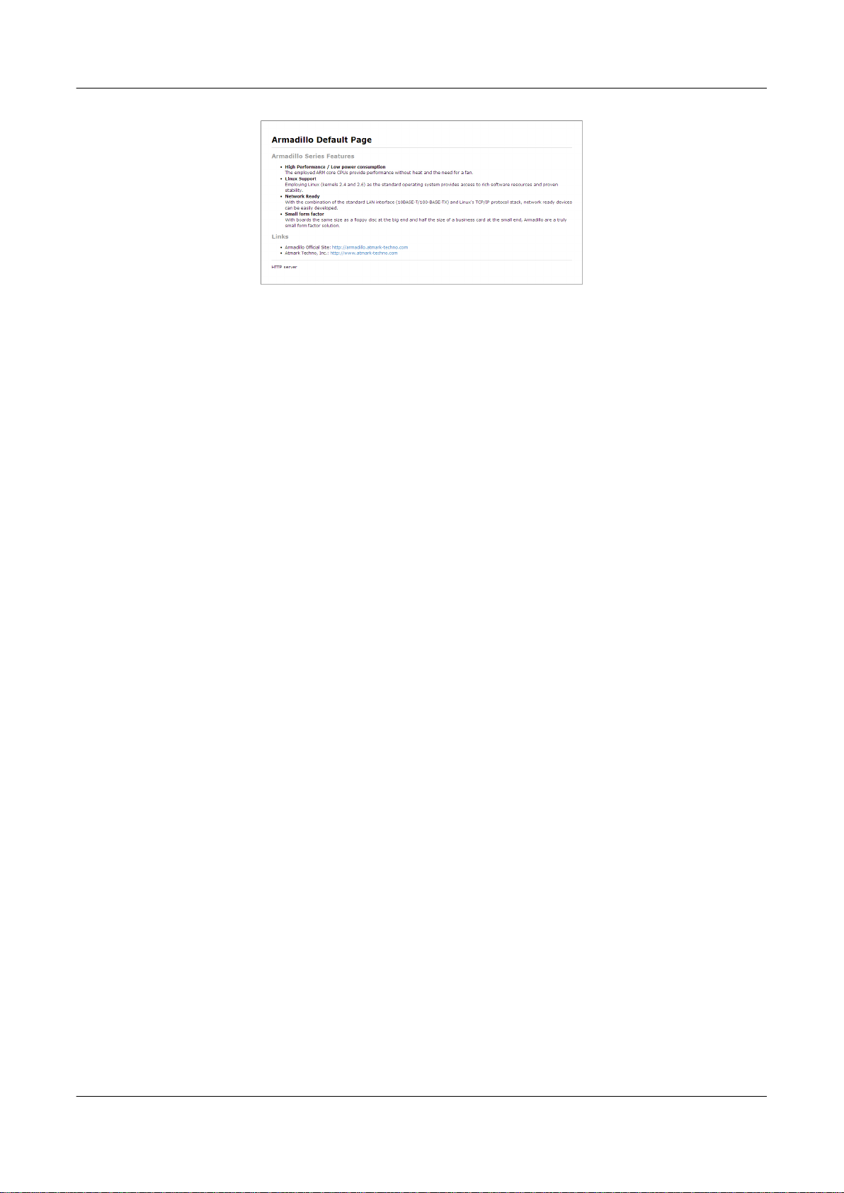
Armadillo-440 LCD Model Development Set Startup Guide
Network
Figure 6.26. Web Server Top Page
If "http on armadillo440 [00:11:0C:XX:XX:XX]" is not displayed in the Explorer Bar, please refer to Section 13.2, “The
Armadillo Cannot Be Found with Bonjour”. If "AT Admin" is not displayed, please correctly configure the PC side network
settings by referring to Section 6.1, “Default Network Connection Mechanisms”.
6.5.3. Bonjour Hostnames
The hostname shown with Bonjour will be the same as the hostname configured on the Armadillo (this is set to armadillo440-0 by default). As the Bonjour network name is ".local," the URL opened with Bonjour in the web browser will
normally be http://armadillo440-0.local/.
However, if two or more hosts with the same hostnames exist on the same network (like when multiple Armadillo are
connected in their default state), the number at the end of the hostname will change from the second host onwards. For
example, with Armadillo in their default state, the second hostname would be "http://armadillo440-1.local/" and the third
"http://armadillo440-2.local/." Please note that in this situation the hostname (as configured in "AT Admin") of the second
host onwards will not match its Bonjour hostname.
In this situation, the MAC address can be used to identify each individual unit. The MAC address displayed in the Internet
Explorer Bonjour list can be compared with the sticker attached to each unit. Refer to Figure 6.25, “"Bonjour" Explorer Bar”.
51
Page 52
Armadillo-440 LCD Model Development Set Startup Guide Storage
Chapter 7. Storage
7.1. Devices Which Can Be Used as Storage
The devices shown in Table 7.1, “Storage Devices” can be used as storage on Armadillo-440.
Table 7.1. Storage Devices
Device Type Disk Device First Partition
USB Flash Memory
microMMC / microSD Cards
7.2. Using Storage
Using a microSD card as an example, the following explains how to use storage.
On Linux all accessible files and directories are brought together in one tree structure. Adding the filesystem of a storage
device to this tree structure is called mounting. The mount command used to perform this mounting.
/dev/sd* /dev/sd*1
/dev/mmcblk* /dev/mmcblk*p1
The typical format used with the mount command is as shown in Figure 7.1, “mount Command Format”.
mount -t fstype device dir
Figure 7.1. mount Command Format
The filesystem is specified following the -t option
[1]
. vfat is specified for FAT32 filesystems
filesystems.
The device file name of the storage device is specified for device. For partition 1 on a microSD card, this will be /
dev/mmcblk0p1, and for partition 2 it will be /dev/mmcblk0p2.
The directory where the filesystem on the storage device is to be mounted is specified for dir.
When the command shown in Figure 7.2, “Mounting Storage” is executed while a microSD is in the microSD slot, the
filesystem on the microSD card is mounted to the /mnt directory. The files on the microSD will now be visible under the /
mnt directory.
[armadillo ~]# mount -t vfat /dev/mmcblk0p1 /mnt
[2]
, and ext3 for EXT3
Figure 7.2. Mounting Storage
In order to safely remove storage it must be unmounted. The umount command is used to perform the unmounting. The
directory where the device to unmount is mounted is specified as its option.
[1]
The filesystem option may be omitted. When it is omitted, the mount command attempts to guess the filesystem type. As this guess may not always be
correct, it is best to specify it when the filesystem type is known.
[2]
Normally, purchased microSD cards come formatted with a FAT32 filesystem.
52
Page 53

Armadillo-440 LCD Model Development Set Startup Guide
[armadillo ~]# umount /mnt
Storage
Figure 7.3. Unmounting Storage
7.3. Changing and Formatting Storage Partitions
Normally, purchased microSD cards and USB memory come with one partition which is formatted with a FAT32 filesystem.
The fdisk command is used to alter the partition structure. An example of using the fdisk command to alter a microSD
card that has one partition so that it is split into two partitions is shown in Figure 7.4, “Altering Partitions with the fdisk
Command”. The existing partition is first deleted and then two new primary partitions are created. The first partition is
assigned 100MByte, and the second partition is assigned the remaining space. The first partition will be /dev/mmcblk0p1
and the second /dev/mmcblk0p2. For more details on using the fdisk command, please refer to its man page.
[armadillo ~]# fdisk /dev/mmcblk0
The number of cylinders for this disk is set to 62528.
There is nothing wrong with that, but this is larger than 1024,
and could in certain setups cause problems with:
1) software that runs at boot time (e.g., old versions of LILO)
2) booting and partitioning software from other OSs
(e.g., DOS FDISK, OS/2 FDISK)
Command (m for help): d
Selected partition 1
Command (m for help): n
Command action
e extended
p primary partition (1-4)
p
Partition number (1-4): 1
First cylinder (1-62528, default 1):
Using default value 1
Last cylinder or +size or +sizeM or +sizeK (1-62528, default 62528): +100M
Command (m for help): n
Command action
e extended
p primary partition (1-4)
p
Partition number (1-4): 2
First cylinder (3054-62528, default 3054):
Using default value 3054
Last cylinder or +size or +sizeM or +sizeK (3054-62528, default 62528):
Using default value 62528
Command (m for help): w
The partition table has been altered!
Calling ioctl() to re-read partition table.
mmcblk0: p1 p2
53
Page 54

Armadillo-440 LCD Model Development Set Startup Guide Storage
mmcblk0: p1 p2
Syncing disks.
Figure 7.4. Altering Partitions with the fdisk Command
The mkfs.vfat command is used to format a storage device with a FAT32 filesystem, while the mke2fs command is used
for EXT2 and EXT3 filesystems. A command example where partition 1 on a microSD card is formated with an EXT3
filesystem is shown in Figure 7.5, “EXT3 Filesystem Creation”.
[armadillo ~]# mke2fs -j /dev/mmcblk0p1
Figure 7.5. EXT3 Filesystem Creation
54
Page 55

Armadillo-440 LCD Model Development Set Startup Guide Sound
Chapter 8. Sound
The Armadillo-440 LCD Model incorporates an audio codec and can both record and play sound. For the specifications of the audio driver, refer to "Audio" in the "Armadillo-400 Series Software Manual." This chapter explains how to
record and play sound.
8.1. Sound Functionality with ALSA
There are two ways to provide audio functionality on Linux: ALSA
Armadillo-440 LCD Model.
[1]
and OSS
[2]
. ALSA is used by default on the
8.1.1. Playing Back Sound
The aplay command is used to play sound with ALSA. See below for details on the options. For information on all
available options, refer to the aplay help.
-M
Use memory mapped I/O for the audio stream.
-t
Specify the file type. Refer to the help for what file types can be specified.
-f
Specify the sample format. Refer to the help for what sample formats can be specified.
-d
End after the specified number of seconds.
-l
List all sound cards and audio devices.
-L
List all defined PCM.
-c
Specify the number of channels.
-r
Specify the sample rate.
-D
Specify the PCM.
[1]
Advanced Linux Sound Architecture http://alsa.sourceforge.net
[2]
Open Sound System http://developer.opensound.com/
55
Page 56

Armadillo-440 LCD Model Development Set Startup Guide
-h
Display help.
[armadillo ~]# aplay -M -twav sample.wav
Figure 8.1. Playing Back Sound
8.1.2. Recording
The arecord command is used to record sound with ALSA.
The arecord options are the same as those for aplay.
[armadillo ~]# arecord -M -twav -fS16_LE -r48000 sample.wav
Figure 8.2. Recording Sound
Sound
8.1.3. Changing Volume
The amixer command is used to change the recording and playback volume with ALSA.
The control name to be changed should be specified for [control]. Refer to Table 8.1, “Control Names” for the supported
control names.
Table 8.1. Control Names
Control Description
'Headphone' Headphone volume
Mic Microphone volume
Enter the command below to check all of the controls and their values.
[armadillo ~]# amixer
Figure 8.3. Checking Volumes
The volume is specified in place of [value] with a range of 0 (mute) to 63 (max).
[armadillo ~]# amixer set [control] [value] unmute
Figure 8.4. Changing Volume
56
Page 57
Armadillo-440 LCD Model Development Set Startup Guide
Input Devices
Chapter 9. Input Devices
This chapter explains how to receive events from input devices. On the Armadillo-440 LCD Model, the touch screen
and buttons are supported as input devices. For the specifications of the touch screen and button drivers, refer to the
"Touch Screen" and "Buttons" chapters in the "Armadillo-400 Series Software Manual."
9.1. evtest
The evtest command can be used to check what kind of input events are occurring. evtest is used as shown in Figure 9.1,
“evtest Command Format”.
[armadillo ~]# evtest /dev/input/eventX
Figure 9.1. evtest Command Format
For the device file to specify in place of /dev/input/eventX, refer to Table 9.1, “Input Device Files”.
Table 9.1. Input Device Files
Device File Device
/dev/input/event0 Buttons
/dev/input/event1 Touch Screen
The event device file numbers are determined by the order the input devices are
detected. Therefore, if another input device such as a USB keyboard is detected at
boot time, the event device numbers may change.
In the default Armadillo-440 LCD Model userland, the input device file name
specified when starting xfbdev is fixed. Therefore if another input device such as a
USB keyboard has been connected, it is possible that touch screen control will not
work. To use other input devices, please connect them after booting.
Enter Ctrl + C to stop evtest.
9.2. swmgr
The swmgr command can be used to execute another command when a button is pressed.
swmgr is used as shown in Figure 9.2, “swmgr Command Format”.
[armadillo ~]# swmgr [BUTTON] [LOOP] [COMMAND]
Figure 9.2. swmgr Command Format
Specify the button to receive events from in place of BUTTON. For supported buttons, refer to Table 9.2, “Buttons
Supported By swmgr”.
57
Page 58
Armadillo-440 LCD Model Development Set Startup Guide
Table 9.2. Buttons Supported By swmgr
Buttons Description
sw0 SW1
sw1 LCD_SW1
sw2 LCD_SW2
sw3 LCD_SW3
Specify the number of times to wait for an event in place of LOOP. Specify 0 for an unlimited number of times.
Specify the operation to execute when an event occurs in place of COMMAND.
9.3. swmgr Example
The following displays time information when SW1 is pressed.
[armadillo ~]# swmgr sw0 1 date
Figure 9.3. swmgr Example 1
Input Devices
The following turns LED3 on when LCD_SW1 is pressed and turns it off when LCD_SW2 is pressed.
[armadillo ~]# swmgr sw1 0 echo 1 > /sys/class/leds/red/brightness &
[armadillo ~]# swmgr sw2 0 echo 0 > /sys/class/leds/red/brightness &
Note: Execute the following command to stop the operations.
[armadillo ~]# killall swmgr
Figure 9.4. swmgr Example 2
58
Page 59
Armadillo-440 LCD Model Development Set Startup Guide
Other Devices
Chapter 10. Other Devices
10.1. LED
The Armadillo-400 Series LEDs are supported as LED class devices. The LEDs can be controlled with the files under
the LED class directories. For the LED class directories and corresponding LEDs, refer to Table 10.1, “LEDs and LED
Class Directories”.
Table 10.1. LEDs and LED Class Directories
LED Class Directory Description
/sys/class/leds/red/ LED3 (red)
/sys/class/leds/green/ LED4 (green)
/sys/class/leds/yellow/ LED5 (yellow)
10.1.1. Activating and Deactivating LEDs
LEDs can be turned on and off by writing an appropriate value to the brightness file under the LED class directory. A
value between 0 and 255 can be written to the brightness file.
Writing any value apart from 0 to the brightness file turns the LED on. As the Armadillo-400 Series LEDs do not have
brightness control functionality, the value has no effective meaning.
[armadillo ~]# echo 1 > /sys/class/leds/yellow/brightness
Figure 10.1. Turning LED5 On
Writing 0 to the brightness file turns the LED off.
[armadillo ~]# echo 0 > /sys/class/leds/yellow/brightness
Figure 10.2. Turning LED5 Off
The current state of the LED can be obtained by reading the brightness file. 0 represents the off state, and any other value
represents an on state.
[armadillo ~]# cat /sys/class/leds/yellow/brightness
0
Figure 10.3. Displaying LED5 State
10.1.2. Using Triggers
A trigger to turn the LED on and off can be set by writing an appropriate value to the trigger file under the LED class
directory. For values supported by the trigger file, refer to Table 10.1, “LEDs and LED Class Directories”.
59
Page 60
Armadillo-440 LCD Model Development Set Startup Guide Other Devices
Table 10.2. trigger Configuration
Configuration Description
none No trigger is set.
mmc0 LED acts as microSD card access lamp.
timer Blink on and off at certain intervals. After setting this trigger, delay_on and delay_off files appear under the LED class directory
heartbeat Blink on and off like a heart beat.
default-on Used mainly from the kernel. The LED is turned on at boot time.
which can be used to set the on and off times in millisecond increments.
Executing the commands below will cause LED3 to repeatedly turn on for 1 second and then off for 500 milliseconds.
[armadillo ~]# echo timer > /sys/class/leds/red/trigger
[armadillo ~]# echo 1000 > /sys/class/leds/red/delay_on
[armadillo ~]# echo 500 > /sys/class/leds/red/delay_off
Figure 10.4. Specifying timer as Trigger for LED3
The current trigger of the LED can be obtained by reading the trigger file. The value enclosed in [] is the current trigger.
[armadillo ~]# cat /sys/class/leds/yellow/trigger
[none] mmc0 timer heartbeat default-on
Figure 10.5. Displaying LED3 Timer
10.2. GPIO
The Armadillo-400 Series GPIO are supported as GPIO class devices. The GPIO can be controlled with the files under
the GPIO class directories. For the GPIO class directories and corresponding GPIO, refer to Table 10.3, “GPIO and GPIO
Class Directories”.
Table 10.3. GPIO and GPIO Class Directories
GPIO Class Directory Description
/sys/class/gpio/CON9_1/ CON9 pin 1
/sys/class/gpio/CON9_2/ CON9 pin 2
/sys/class/gpio/CON9_11/ CON9 pin 11
/sys/class/gpio/CON9_12/ CON9 pin 12
/sys/class/gpio/CON9_13/ CON9 pin 13
/sys/class/gpio/CON9_14/ CON9 pin 14
/sys/class/gpio/CON9_15/ CON9 pin 15
/sys/class/gpio/CON9_16/ CON9 pin 16
/sys/class/gpio/CON9_17/ CON9 pin 17
/sys/class/gpio/CON9_18/ CON9 pin 18
/sys/class/gpio/CON9_21/ CON9 pin 21
/sys/class/gpio/CON9_22/ CON9 pin 22
/sys/class/gpio/CON9_23/ CON9 pin 23
/sys/class/gpio/CON9_24/ CON9 pin 24
/sys/class/gpio/CON9_25/ CON9 pin 25
/sys/class/gpio/CON9_26/ CON9 pin 26
/sys/class/gpio/CON9_27/ CON9 pin 27
/sys/class/gpio/CON9_28/ CON9 pin 28
60
Page 61
Armadillo-440 LCD Model Development Set Startup Guide
Other Devices
CON14 pin 3 and CON14 pin 4 were configured to be used as GPIO by default in
linux-2.6.26-at7 (linux-a400-1.00.bin.gz). In linux-2.6.26-at8 (linuxa400-1.01.bin.gz) and later, this was changed so that they are configured to be used
as I2C2 by default. Please be aware of this change when using CON14 pin 3 and
CON14 pin 4.
10.2.1. Changing I/O Direction
The I/O direction can be changed by writing an appropriate value to the direction file under the GPIO class directory. For
values supported by the direction file, refer to Table 10.4, “direction Configuration”.
Table 10.4. direction Configuration
Configuration Description
high Set I/O direction to OUTPUT. The input level can be obtained and set in this state. The input level will be HIGH.
out Set I/O direction to OUTPUT. The input level can be obtained and set in this state. The input level will be LOW.
low This is the same as setting "out".
in Set I/O direction to INPUT. The input level can be obtained but not set in this state.
10.2.2. Obtaining Input Level
The input level can be obtained by reading the value file under the GPIO class directory. 0 represents a LOW level and
1 a HIGH level. The input level can be obtained both when the I/O direction is set to INPUT and OUTPUT.
[armadillo ~]# cat /sys/devices/virtual/gpio/CON9_1/value
0
Figure 10.6. Obtaining CON9_1 Input Level
10.2.3. Configuring Input Level
The input level can be set by writing an appropriate value to the value file under the GPIO class directory. 0 represents
a LOW level and 1 a HIGH level. Input level configuration can only be carried out when the I/O direction is set to OUTPUT.
[armadillo ~]# echo 1 > /sys/devices/virtual/gpio/CON9_2/value
Figure 10.7. Configuring CON9_2 Input Level
10.3. RTC
As the Armadillo-440 LCD Model incorporates a calendar clock (Real Time Clock), the date and time will continue to
be displayed correctly even after turning the power off and on.
To set time information to the RTC, first set the system clock. After that, then set the hardware clock (RTC) to match the
system clock.
10.3.1. Setting System Clock with date
The time format used as an argument to the date command is: MMDDhhmmCCYY.ss. In the example below, the date
and time are set to 1/23/2000 4:56:00.
61
Page 62
Armadillo-440 LCD Model Development Set Startup Guide Other Devices
[armadillo ~]#date Displays the current system clock
[armadillo ~]#date 012304562000.00
[armadillo ~]#date
Check that the system clock was set correctly
10.3.2. Setting System Clock with NTP Client
The system clock can be set using the NTP client. For more information, refer to Section 6.4.5, “NTP Client”.
10.3.3. Setting Hardware Clock
[armadillo ~]#hwclock Displays the hardware clock
[armadillo ~]#hwclock --utc --systohc Sets hardware clock in UTC
[armadillo ~]#hwclock
Check that the hardware clock was set correctly
62
Page 63
Armadillo-440 LCD Model Development Set Startup Guide
Boot Modes and Bootloader Functions
Chapter 11. Boot Modes and Bootloader Functions
This chapter explains about the boot modes on the Armadillo and also about the boot configuration functions of Hermit-At, the default bootloader.
JP1 can be used to select between the on-board flash memory boot mode and the UART boot mode on Armadillo-440.
In the on-board flash memory boot mode, the bootloader stored in the bootloader region of flash memory is booted. The
UART boot mode is used for system restore when, for example, the bootloader stored in flash memory has been damaged. For more information, refer to "Restoring Bootloader to Factory State" in the "Armadillo-400 Series Software
Manual."
11.1. Boot Mode Selection
Boot mode selection is determined by the configuration of JP2. Each boot mode is detailed in Table 11.1, “Boot Mode”.
Table 11.1. Boot Mode
Mode JP2 Description
Auto-boot Open The Linux kernel is automatically booted after power on.
Maintenance Short The Hermit-At command prompt that can be used for changing configuration is started.
11.2. Linux Kernel Boot Option Configuration
Various settings including console and root filesystem settings can be changed by specifying the appropriate Linux kernel
boot options. The following details some options typically used with Armadillo.
The setenv function of Hermit-At is used for this configuration. Parameters set with setenv are saved to flash memory
and remain in effect even after rebooting.
The clearenv command is used to clear any set parameters.
hermit> clearenv
Figure 11.1. Linux Kernel Boot Option Clear
Hermit-AT Modes
Hermit-AT has two modes: the "interactive mode" which displays the command
prompt and operates interactively, and the "batch mode" for communicating with
the Hermit-AT downloader. The command prompt and entered characters are not
displayed in batch mode, but commands can be executed.
Hermit-AT is always in interactive mode after booting. To move from interactive
mode to batch mode enter a tilde "~" and to move from batch mode to interactive
mode enter an exclamation mark "!".
63
Page 64
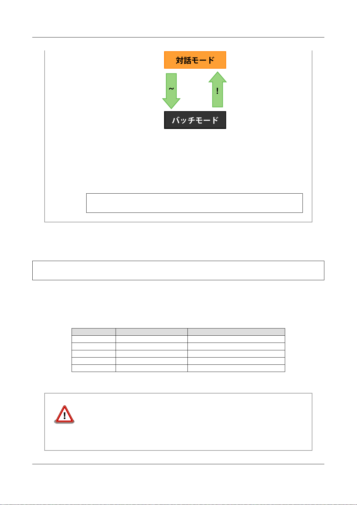
Armadillo-440 LCD Model Development Set Startup Guide
Hermit-AT moves to batch mode when communicating with the Hermit-AT downloader. This is because the Hermit-AT downloader sends a tilde in order to establish
the communication.
When moving from interactive mode to batch mode and when an entered command
succeeds in batch mode the following is displayed.
+OK
Boot Modes and Bootloader Functions
11.2.1. Console Configuration
To change the output console of the boot log, set the console parameter as shown below.
hermit> setenv console=ttymxc1
Figure 11.2. Console Designation
For the effects on logging for each setting, refer to Table 11.2, “Console Configuration Effect on Output Destination”.
Table 11.2. Console Configuration Effect on Output Destination
Console Option Boot Log Output Destination Maintenance Mode Prompt Destination
Other (tty1 etc) The specified console
[a]
Effective from next boot.
[b]
No log output from bootloader.
ttymxc1 CON3 (Serial Interface 1) CON3 (Serial Interface 1)
ttymxc2 CON9 (Serial Interface 2) CON9 (Serial Interface 2)
ttymxc4 CON9 (Serial Interface 3) CON9 (Serial Interface 3)
null None CON3 (Serial Interface 1)
[b]
CON3 (Serial Interface 1)
If the kernel console is set with setenv, this configuration is also carried over to the
Hermit-At console.
[a]
For example, if the kernel console is set to ttymxc2, the Hermit-At console will also
change to ttymxc2 from the next boot.
64
Page 65

Armadillo-440 LCD Model Development Set Startup Guide Boot Modes and Bootloader Functions
11.2.2. Specifying Image File to Boot
On the Armadillo-440, in addition to on-board flash memory it is also possible to boot an image file from storage or a
tftp server. For more information, refer to "Kernel and Userland Placement" in the "Armadillo-400 Series Software Manual."
11.2.3. Other Boot Options
There are a large number of options available aside from those introduced here. For more information refer to a book on
the Linux kernel or the documentation included in the Linux kernel source code (kernel-source/Documentation/
kernel-parameters.txt).
11.2.4. Boot Option Configuration Examples
• To set the console to Serial Interface 2
hermit> setenv console=ttymxc2
Figure 11.3. Boot Option Configuration Example 1
• To set the console to the LCD panel
hermit> setenv console=tty1
Figure 11.4. Boot Option Configuration Example 2
11.3. Note on Bootloader Versions
When a bootloader image based on hermit-at v2.0.0 source (loader-armadillo4x0-v2.0.0.bin etc) and a kernel image based
on linux-2.6.26-at7 source (linux-a400-1.00.bin.gz etc) are used on Armadillo-440 board revision Rev.C1 or later boards
(S/N 100201-2195 or greater), a problem exists where the kernel may not boot. This problem only occurs with the above
combination.
On Armadillo-440 board revision Rev.C1 or later boards (S/N 100201-2195 and greater), please use a bootloader image
based on hermit-at v2.0.1 or later source (loader-armadillo4x0-v2.0.1.bin or later).
[1]
[1]
On Armadillo-440 Rev.C1 and later boards, loader-armadillo4x0-v2.0.1.bin or a later version is written to flash memory in the default factory state.
65
Page 66
Armadillo-440 LCD Model Development Set Startup Guide
Config Region - Configuration File Storage
Chapter 12. Config Region - Configuration File Storage
The config region is a flash memory region used to save files in order to maintain data even after hardware resets. The
flatfsd command is used to write data to and read data from the config region.
12.1. Reading from the Config Region
The command shown below is used to read from the config region. The files read from the config region are created under
the /etc/config directory.
[armadillo ~]# flatfsd -r
Figure 12.1. Reading from the Config Region
In the default software, the files are automatically read out from the config region
at boot time. If the config region data has been damaged, it is replaced with the
contents of the /etc/default directory.
12.2. Saving to the Config Region
The command shown below is used to save to the config region. The files saved to the config region are those present
under the /etc/config directory.
[armadillo ~]# flatfsd -s
Figure 12.2. Saving to the Config Region
If the save to the config region is not carried out, then changes to the files under
the /etc/config directory will be lost when power is cut.
12.3. Initializing the Config Region
The command shown below is used to initialize the config region. On initialization, the files under the /etc/default
directory are saved to the config region and are then also reproduced under the /etc/config directory.
66
Page 67

Armadillo-440 LCD Model Development Set Startup Guide Config Region - Configuration File Storage
[armadillo ~]# flatfsd -w
Figure 12.3. Config Region Initialization
67
Page 68
Armadillo-440 LCD Model Development Set Startup Guide
Troubleshooting
Chapter 13. Troubleshooting
13.1. The Armadillo Will Not Boot
• Please check that the green LED turns on after connecting power. If it does not turn on, please check that the power
supply is properly connected.
13.2. The Armadillo Cannot Be Found with Bonjour
• Please check that the LAN Link LED is on. If it is not on, please ensure that the LAN cable is inserted correctly.
• Please ensure that there is no router between the PC with Bonjour and the Armadillo. The Armadillo cannot be found
if a router exists between the two.
• If a firewall is active, please ensure that the port "UDP 5353" used by Bonjour is accessible.
13.3. The Screen Does Not Display After Changing the Network Configuration
• A change in the IP address, for example when changing from AUTO IP to a STATIC IP configuration, means that
the correct current IP address corresponding to the hostname also changes. However, depending on the WEB browser,
the cached old IP address may continue to be used and pages accessed via the hostname will not be displayed for a
certain period of time. If this occurs, please close and restart the WEB browser and then access the top page again.
Restarting the browser has been confirmed to alleviate the problem with Internet Explorer Version 6.
• If the screen does not display even after carrying out the procedure described above, it may indicate that the Armadillo's
network connection is in an irregular state. As the changes to the network configuration have not yet been saved to
flash memory at this point, just reboot the Armadillo and then redo the network configuration.
68
Page 69

Armadillo-440 LCD Model Development Set Startup Guide Startup Guide
Revision History
Revision Date Description
1.0.0 2010/03/12 • Initial Release
1.1.0 04/28/2010 • Made correction to message after halt in Figure 4.2, “Shutdown Method”
• Added Section 5.6, “RTC (Real-Time Clock)”
• Made correction to configurable volume range in Section 8.1.3, “Changing Volume”
• Added note about function change of pins 3/4 on CON14 to Section 10.2,
“GPIO”
• Added precaution note when using board revision Rev.C1 to Section 11.3, “Note on Bootloader Versions”
1.1.1 20/08/2010 • Made correction to RS232C level conversion adaptor connection method
in Section 3.1, “Layout Diagram”
1.1.2 12/22/2010 • Moved precautions to Chapter 2, Precautions
• Corrected inconsistent use of product names
1.1.3 03/25/2011 • Added explanation of Hermit-AT modes to Section 11.2, “Linux Kernel
Boot Option Configuration”
• Changed "Touch Panel" to "Touch Screen" in Chapter 5, Function Tests
• Updated company address
• Corrected various errors and inconsistencies
• Updated title and content of Section 7.2, “Using Storage”
• Updated title and content of Section 7.3, “Changing and Formatting Storage Partitions”
1.1.4 08/26/2011 • Added recommended settings for serial communication software to Section 3.5, “Serial Console Software Configuration”
1.1.5 10/21/2011 • Updated web site name
Page 70

Armadillo-440 LCD Model Development Set Startup Guide
Version 1.1.5
2012/02/29
Atmark Techno, Inc.
060-0035 AFT Bldg., N5E2, Chuo-ku, Sapporo TEL 011-207-6550 FAX 011-207-6570
 Loading...