

Page 1
USER MANUAL
AV SWITCHER USER GUIDE
AT-AV0404 TO AV128128
Toll free: 1-877-536-3976
Local: 1-408-962-0515
www.atlona.com
Page 2

TABLE OF CONTENTS
1. SAFETY OPERATION GUIDE 2
1.1 NOTICE 2
2. INTRODUCTION 3
2.1 INSTALLATION 4
3. CONNECTOR TYPES 13
3.1 CONNECTING THE AV SWITCHER 14
4. OPERATION CONTROLS FOR AV0404 15
4.1 OPERATION CONTROLS FOR AV1616 16
4.2 ADDITIONAL CONTROLS FOR AV32, AV48, AV64, AV96, AV128 17
4.3 REMOTE CONTROL OPERATION 19
5. OPERATION OF APPLICATION SOFTWARE 19
5.1 KEYBOARD TAB 20
5.2 AUTO TAB 21
5.3 CUSTOM CODE TAB 21
5.4 CODE GROUP TAB 22
5.5 SEND / RECIEVE CODE LIST TAB 24
6. RS-232 OPERATION 25
7. TECHNICAL SPECIFICATIONS 26
8. TROUBLESHOOTING 29
9. SAFETY INFORMATION 30
10. WARRANTY 31
11. ATLONA PRODUCT REGISTRATION 32
Toll free: 1-877-536-3976
Local: 1-408-962-0515
1
www.atlona.com
Page 3

Safety Operation Guide
In order to ensure the credibility and the user’s safety, please comply with the following items during installation, maintenance and operation of the switch.
1. The switch must be in stable position. Use only the power supply that comes with unit. Do not use an
alternate as it may damage it.
2. Do not place the switcher near hot or cold surfaces or sources.
3. To avoid any damage by over heating, please keep the environment in good ventilation to radiate the
heat when running the switcher.
4. The switcher should be turned off when it is not used.
5. Please do not attempt to take cover off the switcher for there is a high-volt age component inside that
could cause electric shock.
6. Do not splash any liquid or chemical on or near the equipment.
7. Please make sure all the wiring are in working condition and are not cut or damaged.
NOTICE
This VGA Switchers User Manual can be used for other VGA matrix switcher models. This manual is only an
instruction for operators, not for any maintenance usage. Any changes of functions and parameters since
then will be informed separately. This manual is copyright Atlona Technologies. All rights reserved. No part of
this publication may be copied or reproduced without the prior written consent of Atlona Technologies.
Please check Atlona website updates.
http://www.atlona.com
Toll free: 1-877-536-3976
Local: 1-408-962-0515
2
www.atlona.com
Page 4
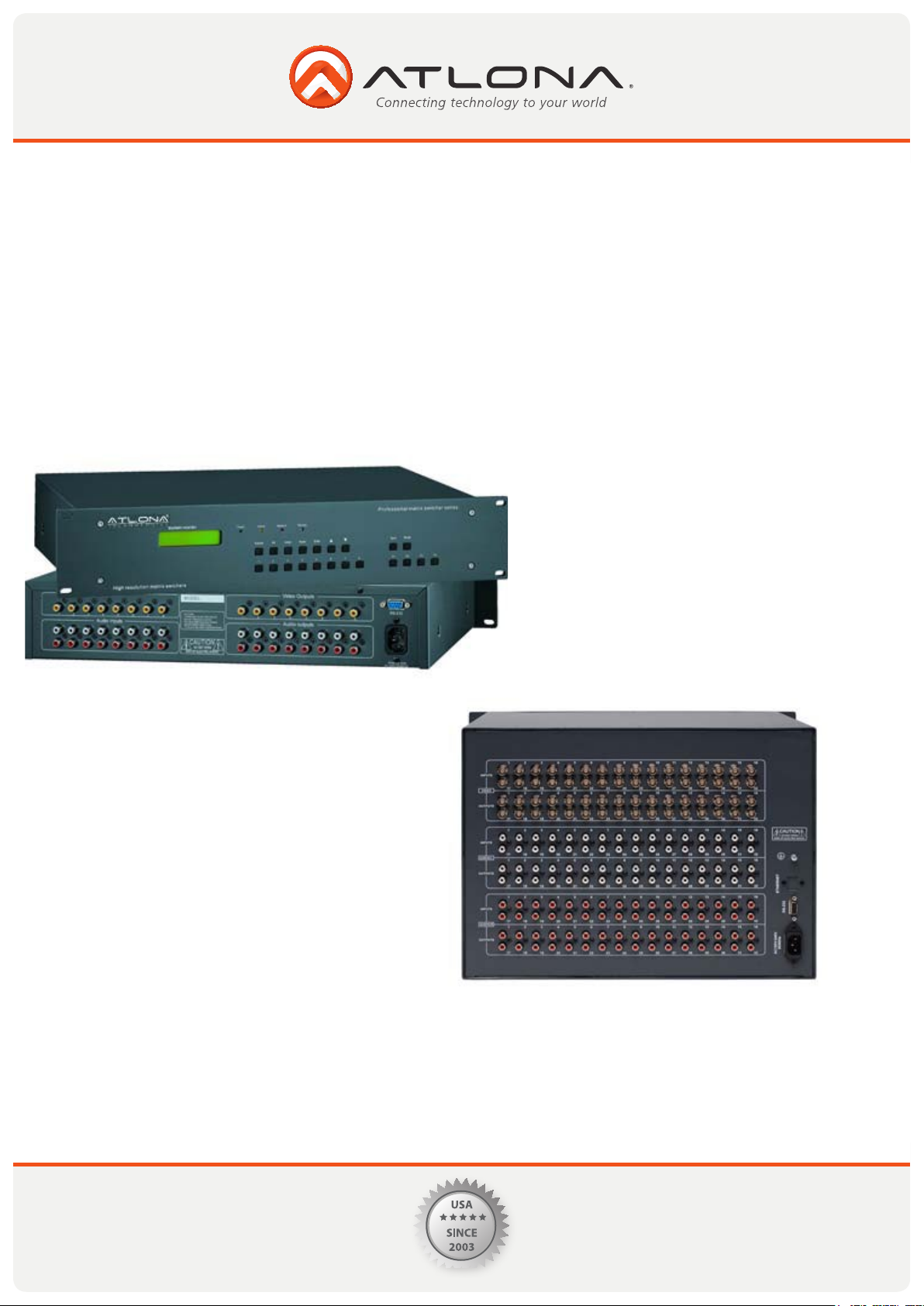
INTRODUCTION
The AV series switcher is a high-performance professional computer and audio signal switcher that
can be used for cross switching multiple computer and audio signals. The AV series switcher mostly apply in
broadcasting TV engineering, multi-media meeting room, big screen display engineering, television education, command control center or for other like applications. It provides power-fail locale protection function,
LCD displaying, shortcut selecting and saving function. With RS232 interface, it can be controlled with PC,
remote control system and any other 3rd party control systems. This user manual takes VGA0808 as the example; other models can take reference from it too.
Toll free: 1-877-536-3976
Local: 1-408-962-0515
3
www.atlona.com
Page 5
INSTALLATION
The VGA Switchers can be easily rack mounted using the rack mount ears located in the front of the
unit. Secure the Switch with standard rack-hole screws. It is recommended to leave a 1U space between the units to have easy access for installation of the cables. When connecting the cables make
sure all cables are connected correctly if not it could cause color loss or will not output a display signal.
Packaging Includes:
• VGA Matrix Switcher
• RS-232 Communication Cord
• Power Supply Cord
• CD with Application SWITCHER 2.0
• User Manual and Quality Guarantee
• Remote Control
Toll free: 1-877-536-3976
Local: 1-408-962-0515
4
www.atlona.com
Page 6
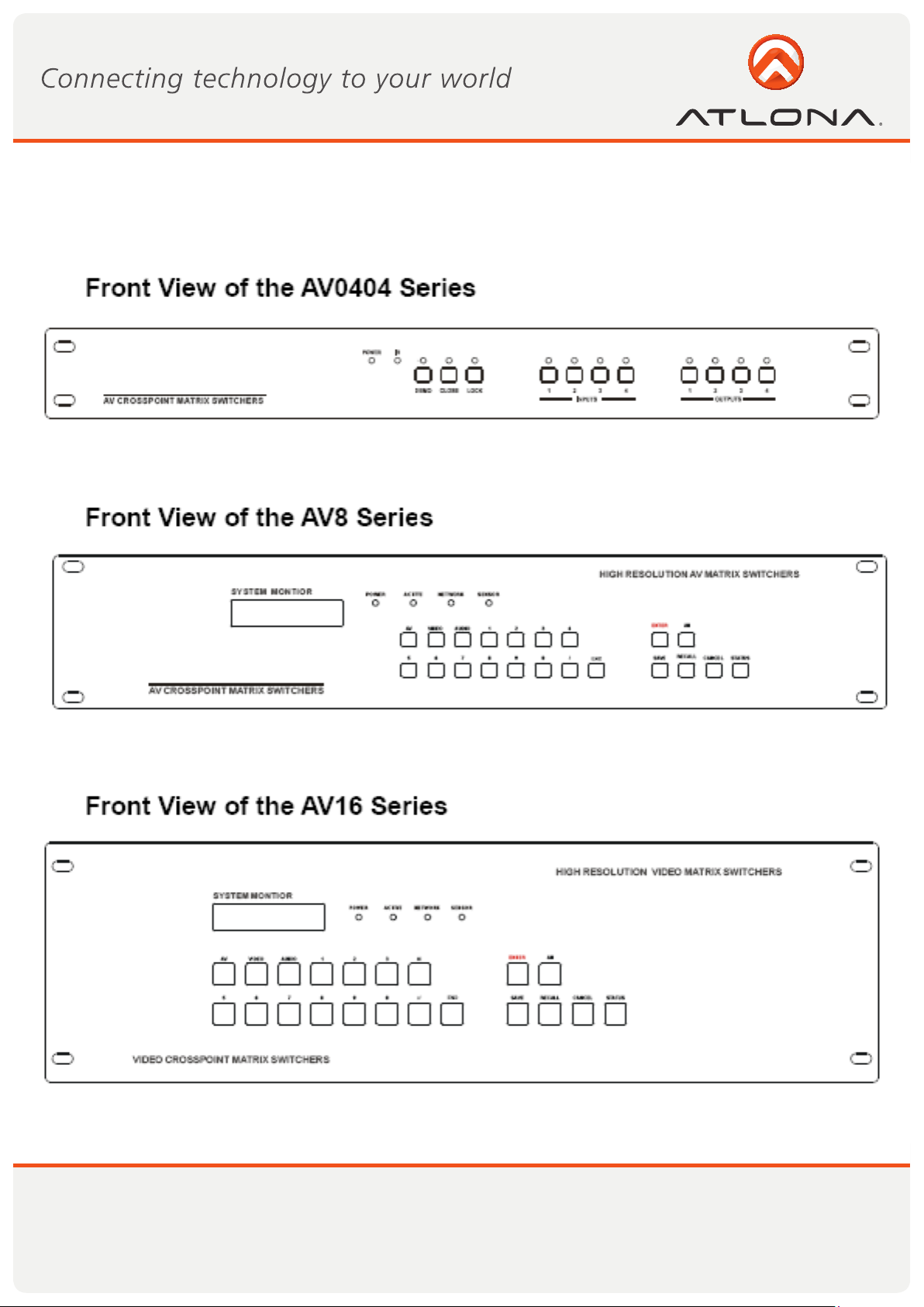
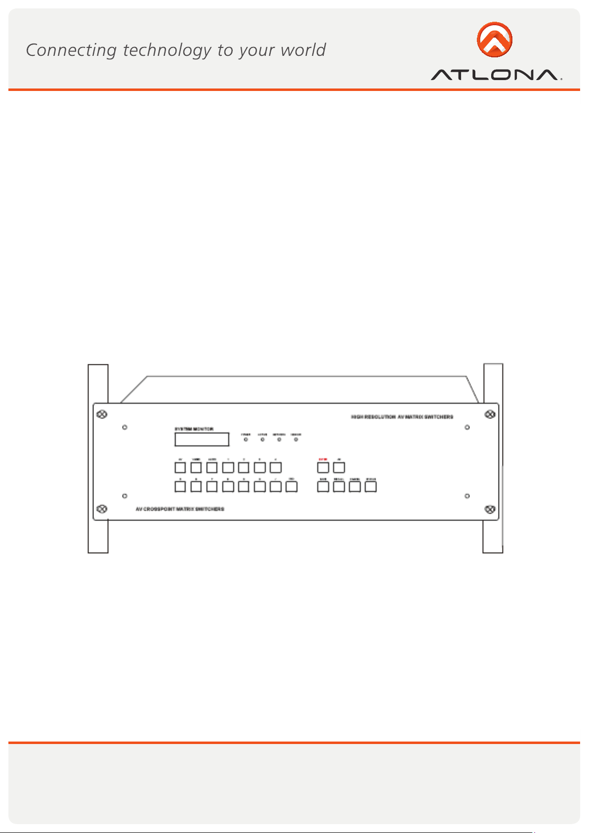
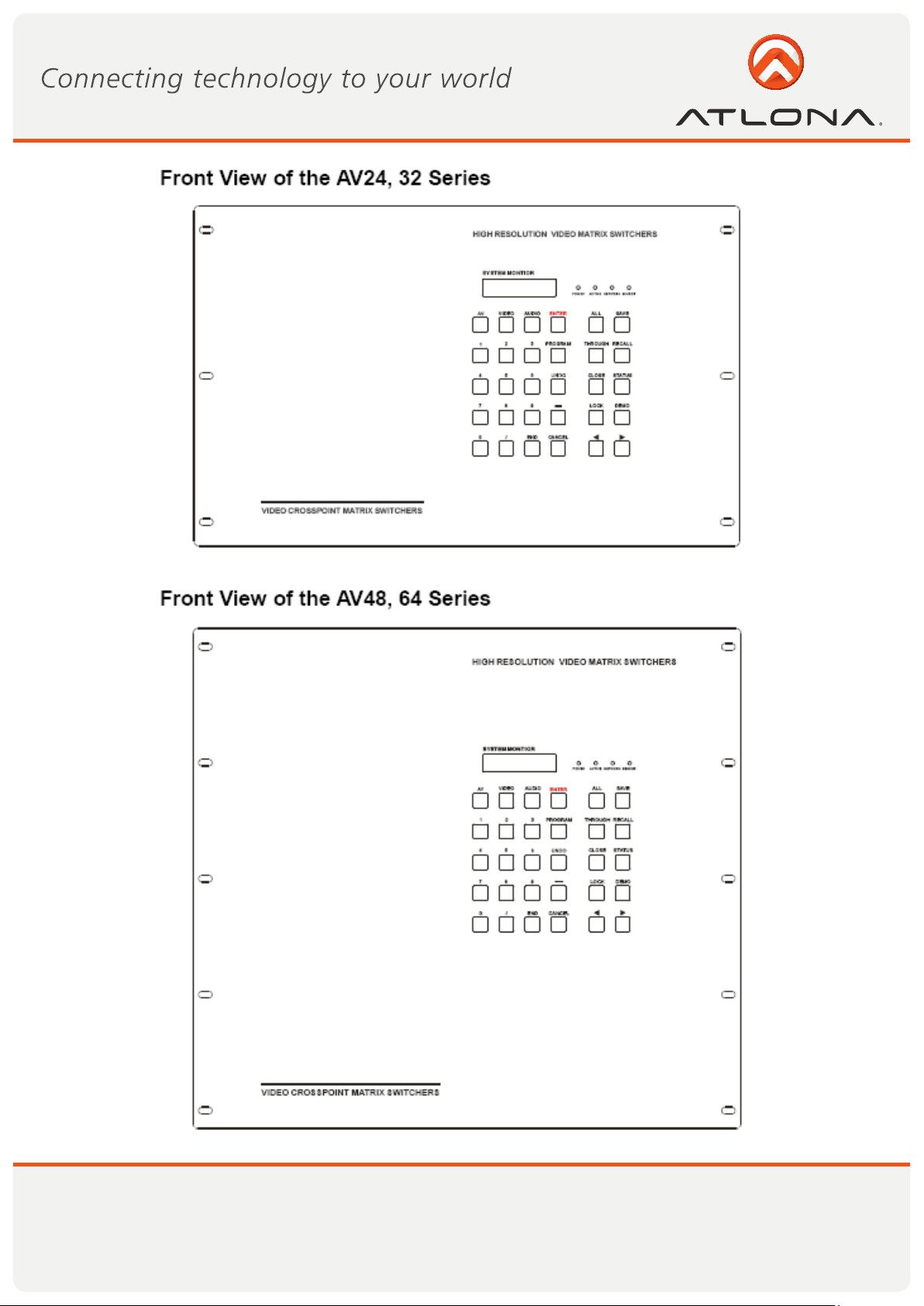
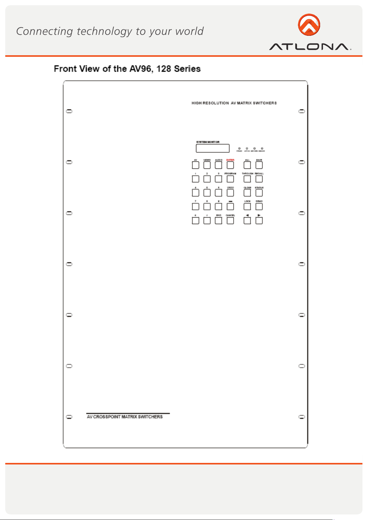
FRONT VIEW OF THE PRODUCT
Toll free: 1-877-536-3976
Local: 1-408-962-0515
5
www.atlona.com
Page 7
Toll free: 1-877-536-3976
Local: 1-408-962-0515
6
www.atlona.com
Page 8
Toll free: 1-877-536-3976
Local: 1-408-962-0515
7
www.atlona.com
Page 9
Toll free: 1-877-536-3976
Local: 1-408-962-0515
8
www.atlona.com
Page 10
Toll free: 1-877-536-3976
Local: 1-408-962-0515
9
www.atlona.com
Page 11

Toll free: 1-877-536-3976
Local: 1-408-962-0515
10
www.atlona.com
Page 12

Toll free: 1-877-536-3976
Local: 1-408-962-0515
11
www.atlona.com
Page 13

Toll free: 1-877-536-3976
Local: 1-408-962-0515
12
www.atlona.com
Page 14

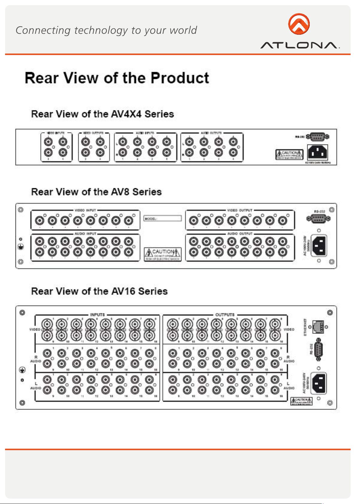
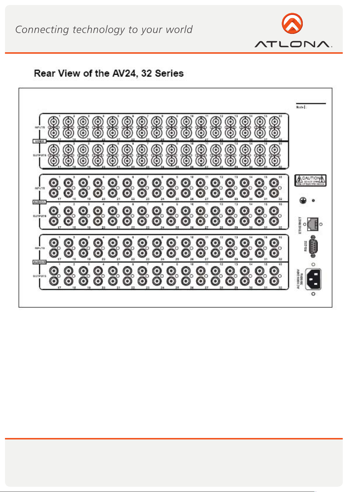
CONNECTOR TYPES
The AV matrix swticher uses 2 types of Video Connectors for 4 Channel and 8 Channel RCA terminals are used.
For 16 Channel, 24 Channel, 32 Channel, 48 Channel, 64 Channel, 96 Channel, 128 Channel BNC female terminals are use. Audio signal I/O terminals make up of 2 Channel, 4 Channel, 8 Channel, 16 Channel, 24 Channel, 32 Channel, 48 Channel, 64 Channel, 96 Channel 128 Channel with 3.8mm captive screw connectors(or
RCA terminals). The AV1616 switcher signal I/O terminals are form Channel 1 to Channel 8 and Channel 9 to
Channel 16 (form left to right, display in two rows), The interfaces are video terminals (BNC), audio left state
terminals (white RCA), audio right state terminals (red RCA). The AV switcher can also be controlled via the
RS-232 communication port. This RS-232 communication port is a female 9-pin D connector. The definition of
its pins is shown in the table below.
PinR S-232 Description
1N /u Not used
2T xT ransmit data
3R xR eceive data
4N /u Not used
5G nd Signal ground
6N /u Not used
7N /u Not used
8N /u Not used
9N /u Not used
The switcher can also be controlled through COM1 or COM2 ports on the computer, To control the switcher,
users may use the application SWITCHER 2.0 in the supplied CD or develop their own control software with
the protocol and control codes.
Toll free: 1-877-536-3976
Local: 1-408-962-0515
13
www.atlona.com
Page 15

CONNECTING THE AV SWITCHER
The VGA matrix switchers may take laptops, DVD players, video tape recorders, camcorders, cable TV and
video their input signal source. Projectors, RP TVs, displayers and amplifiers can be connected on the output
signal.
Toll free: 1-877-536-3976
Local: 1-408-962-0515
14
www.atlona.com
Page 16

AUDIO SIGNAL CONNECTION
“AUDIO INPUTS”, “AUDIO OUTPUTS” audio network interface in RGB matrix switchers can be connected
to the audio signal and amplify sources. Audio connection is little more complicated than video. It has two
types of connection: balanced and unbalanced. The balanced connection transmits a pair of balanced signals with two cables. Because Interferences will have the same intensity and the opposite phases on the two
cables; it will be counteracted in the end. For the low frequency extent of the audio signal, it would be easily
interfered under long distance transmission. Therefore as an anti-interference connection, it is mostly used in
Audio connection of special high end devices.
Connection of captive screw audio connectors (unbalanced/balanced)
OPERATION CONTROLS FOR AV0404
“AV” AV Synchronal button: To transfer video and audio signal synchronously by the switcher
Example: To transfer both the video and the audio signals from input channel No.3 to
output channel No.4.
Operation: Press buttons in this order “3”, “AV”, “4””
“VIDEO” Video button: To transfer only video signals from input channel to output channel
Example: To transfer video signals from input channel No.3 to output channel No.4.
Operation: Press buttons in this order “3”, “VIDEO”, “4”.
“AUDIO” Audio button: To transfer only audio signals from input channel to output channel
Example: To transfer audio signals from input channel No.2 to output channel No.3.
Operation: Press buttons in this order ““2”, “AUDIO”, “3””.
“1,2,3,4” I/O Keypads: Keys to select I/O channels.
Example: To transfer input channel No.3 to output channel No.1
Operation: Press buttons in this order : “3” in IN PUT area, “1” in OUT PUT area.
Toll free: 1-877-536-3976
Local: 1-408-962-0515
15
www.atlona.com
Page 17

OPERATION CONTROLS FOR AV1616
“1,2,3,4” Keypad: Keys to select I/O channels and save/recall preset commands
“AV” AV Synchronal button: To transfer video and audio signal synchronously by the switcher
Example: To transfer both the video and the audio signals from input channel No.3 to
output channel No.6.
Operation: Press buttons in this order “3”, “AV”, “6”, “END”, “ENTER”
“VIDEO” Video button: To transfer only video signals from input channel to output channel
Example: To transfer video signals from input channel No.3 to output channel No.10.
Operation: Press buttons in this order “3”, “VIDEO”, “1”, “0”, “END”,“ENTER”
“AUDIO” Audio button: To transfer only audio signals from input channel to output channel
Example: To transfer audio signals from input channel No.12 to output channel No.6.
Operation: Press buttons in this order “1”, “2”, “AUDIO”, “6”, “END”,“ENTER”
“ / ” Break button: To break different channels in a command
Example: To transfer video and audio signals from input channel No.1 to output
channel No.2,13,6 at the same time
Operation: Press buttons in this order “1”, “AV”, “2”, “/”, “1”,“3”, “/”, “6”, “END”, “EN-
TER”
“END” Ending command button: To finish inputting a command
“ENTER” Performance button: To perform a command after inputting it
“ALL” All button: To transfer an input channel to all output channels or switch off all the output
Example1: To transfer video and audio signals from input channel No.7 to all output
channels
Operation: Press buttons in this order “7”, “ALL”
Note: This command need not follow by “END” & “ENTER”
Example2: To transfer all input signals to the corresponding output channels
respectively. In another word, to switch to this status: 1->1, 2->2, 3->3, 4->4……16->16.
Operation: Press buttons in this order “ALL”, “1”
Example3: To switch off all the output channels
Operation: Press buttons in this order “ALL”, “2”
“SAVE” Save button: To save the present operation to a preset command
Example: To save the present operation to the preset command No.2
Operation: Press buttons in this order “SAVE”, “2”
Note: There are altogether 10 preset commands ranged from No.0 to No.10.
“RECALL” Recall button: To recall the preset command
Example: To recall the preset command No.2
Operation: Press buttons in this order “RECALL”, “2”
Toll free: 1-877-536-3976
Local: 1-408-962-0515
16
www.atlona.com
Page 18

“CANCEL” Cancel button: To return to the standby status without performing any command
Example: To cancel the input instructions “1”, “AV”, “2”, “END”
Operation: Just press button“CANCEL” after the above inputs
“STATUS” Inquiring status button: To inquire the present status
Example1: To inquire the status of output channel No.7
Operation: Press buttons in this order “7”, “STATUS”
Example2: To inquire the status of all the output channels one by one
Operation: Press only the button “STATUS”
ADDITIONAL CONTROLS FOR AV32, AV48, AV64, AV96, AV128
“UNDO” Undo button: To resume to the status before the command just performed
“PROGRAM” Group programming button: To define, recall and clear a group of output channel
Example1: To group the output channels No.1,2,3,4,5 under the Group1
Operation: Press buttons in this order “1”, “Program”, “Program”, “1”, “2”, “3”, “4”, “5”
Example2: To transfer signals from input channel No.1 to Group2
Operation: Press buttons in this order “1”, “Program”, “2”
Example3: To clear the output channels under Group1
Operation: Press buttons in this order “1”, “Program”, “0”
Note: Please clear the group to be set before grouping it.
“ ← ” Backspace button: To backspace the latest input button
“THROUGH” Through button: To transfer the signals directly to the corresponding output
channels
Example: To transfer the signals from input channels No.1,2,3 to their corresponding
output channels
Operation: Press buttons in this order “1”, “/”, “2”, “/”, “3”, “THROUGH”
“CLOSE” Close button: To switch off the output channels
Example: To switch off the output channels No.1,2
Operation: Press buttons in this order “1”, “END”, “2”, “END”, “CLOSE”
“LOCK” Lock button: To lock buttons on the front control panel by pressing it for 3 seconds
Note: When the control panel is being locked, the switcher still can be control via the
RS232 port. To unlock it, a password is needed.
“DEMO” Demo button: To demonstrate the commands one by one every 3 seconds.
Toll free: 1-877-536-3976
Local: 1-408-962-0515
17
www.atlona.com
Page 19

Display feedback on LCD: The video signal of output channel No.4 is transferred from the input channel
No.3 and the audio signal is from the input channel No.2
Toll free: 1-877-536-3976
Local: 1-408-962-0515
18
www.atlona.com
Page 20

REMOTE CONTROL OPERATION
The Matrix can be controlled with the infrared remote control. The function
buttons on the remote are the same as the ones on the front control panel, the
remote uses the same commands and in the same order you would input them.
OPERATION OF APPLICATION SOFTWARE
Switcher 2.0 is a switcher control application compatible with switchers with different inputs and outputs.
Requirments to run the software
Operating System: Window98/2000/NT/XP
Memory: At least 32M
Space in hard disk: At least 10M
CD-ROM
COM Port
Toll free: 1-877-536-3976
Local: 1-408-962-0515
19
www.atlona.com
Page 21

OPERATION CONTROLS FOR AV1616
According to practical needs, user can select and operate at different function tabs such as SYSTEM, AUTO,
KEYBOARD, CUSTOM CODE, CODE GROUP and SEND/RECEIVE CODE LIST.
On the right hand side of the main window, there are 256 buttons representing for the 256 output channels.
When clicking on the button output 1, the text OutPort 1 will appear
“SIGNAL”: Select the switching mode “AV”, “VIDEO” and “AUDIO”
“INPUT A/V PORT”: Select an input A/V channel
“INPUT AUDIO PORT”: Select an input audio channel\
Once the selections have been entered, click “OK”
“MODE”: Select the communication mode between “COM” or “TCP/IP”
“COM”: Select a COM port to control the switcher (if selecting “TCP/IP” as the communication mode, a subpage will appear to inpute the IP address of the swticher)
“Set Password”: Set the password for the control panel on the Matrix (The password must be an 8 digit
number)
“Unlock Keyboard”: Unlock the keyboard of the control panel on the Matrix.
Toll free: 1-877-536-3976
Local: 1-408-962-0515
20
www.atlona.com
Page 22

KEYBOARD TAB
Because the function buttons on this tab are the same with the ones on the front control panel, it shares the
same control operation and command format with the control panel.
Please refer the details in Chapter 7 Operation of the Control Panel
AUTO TAB
This tab is used to test the switcher after connecting it to all the input and outputs device. For example, to
test the function of an RGB64X32 matrix switcher, the Auto Tab is set as below after finishing all the connection.
Switch Mode: “AV”
INPUT: From 1 to 64
OUTPUT: From 1 to 32
Delay: 1000ms (1 second)
Click on the button “START” to perform the test, the matrix switcher will:
Transfer the signals from input channel No.1 to output channel No.1-32;
Transfer the signals from input channel No.2 to output channel No.1-32;
Transfer the signals from the input channel No.64 to the output channel No.1-32;
This switching test will perform this way one by one every second until the test is over.
Toll free: 1-877-536-3976
Local: 1-408-962-0515
21
www.atlona.com
Page 23

CUSTOM CODE TAB
Select between ASCII and HEX format command codes ( for command details, please refer to section)
Help: Displays the list of commans codes.
Send: Sends out the typed commans codes.
For example, to transfer the video and audio signals from the input channel No.1 to the output channel
No.7, and the audio signals from the input channel No.2 to the output channel No.4, just perform the following steps below.
1. Select the “ASCII” as the command codes format;
2. Input the command codes “1B7.2A4.” at the blank of Codes;
3. Click the button “Send” to perform the commands.
Toll free: 1-877-536-3976
Local: 1-408-962-0515
22
www.atlona.com
Page 24

CODE GROUP TAB
New: Creat new a group of preset commands
Open: Opens a group of preset commands
Save: Saves the present group of preset commands
Execute: Executse a selected preset command or a selected group of preset commands
Clear: Clears the feedback window
Add Code ltem: To add another new group of preset commands
Edit: To edit the User’s name (User),
Delete: Deletes the selected group.
Toll free: 1-877-536-3976
Local: 1-408-962-0515
23
www.atlona.com
Page 25

SEND / RECIEVE CODE LIST TAB
Send List window: Lists sent command code
Received List window: Lists feedback from the switcher
Clear: Clears either of the two lists
SEND / RECIEVE CODE LIST TAB
With the application “Switcher 2.00” one is able to control and operate the RGB Matrix remotely
Communication protocol:
Baud rate: 9600 Data bit: 8 Stop bit: 1 Parity bit: none
Toll free: 1-877-536-3976
Local: 1-408-962-0515
24
www.atlona.com
Page 26

Toll free: 1-877-536-3976
Local: 1-408-962-0515
25
www.atlona.com
Page 27

TECHNICAL SPECIFICATIONS
Toll free: 1-877-536-3976
Local: 1-408-962-0515
26
www.atlona.com
Page 28

Toll free: 1-877-536-3976
Local: 1-408-962-0515
27
www.atlona.com
Page 29

Toll free: 1-877-536-3976
Local: 1-408-962-0515
28
www.atlona.com
Page 30

TROUBLESHOOTING
Problem Solution
Output image is displayed with a ghost Check display settings, try another high quality cable
Color loss or no video on output signal Check both the input and output connections
Remote control doesnt work Check batteries, If borken, contact dealer
The switcher cannot be controlled by computer
through COM port.
NO sound when switching with I/O signal. Make sure the beeper is switched on. If it is it may
NO image on output signal Check the Input and Output connectors they may be
Power Indicator doesnt work, no display on LCD no
response to any operation.
Interference in the output image Check to see if the unit is well grounded.
Static gets stronger when connecting BNC connec-
tors
Beepr makes sound. LCD is displaying normally and
there is a returning code. But there isnt any Video or
Audio out.
The swticher cannot be controlled by front panel
keys, RS-232 port or remote control
Check the COM pot in the software.
Make sure the COM is working
be broken inside, contact dealer
lose. Check the connection cord it may be borken.
Check the output device and make sure it is connected to the output channel.
Check the power cord to see it is connected and not
damaged.
The unit is not grounded correctly. Correct issue immeditaly or damage may be caused to the switch.
Check connections, and replace if are damaged
The unit may be broken, contact dealer for repair.
Toll free: 1-877-536-3976
Local: 1-408-962-0515
29
www.atlona.com
Page 31

SAFETY INFORMATION
Safeguards
To reduce the risk of electric shock, do not
expose this product to rain or moisture
If the wall plug does not fit into your local
power socket, hire an electrician to replace
your obsolete socket.
Do not modify the wall plug. Doing so will
void the warranty and safety features.
This equipment should be installed near
the socket outlet and the device should
be easily accessible in the case it requires
disconnection.
Precautions
FCC regulations state that any unauthorized changes or modifications to this equipment, not expressly
approved by the manufacturer, could void the user’s authority to operate this equipment.
Operate this product using only the included external power supply. Use of other power supplies could impair
performance, damage the product, or cause fires.
In the event of an electrostatic discharge this device may automatically turn off. If this occurs, unplug the device
and plug it back in.
Protect and route power cords so they will not be stepped on or pinched by anything placed on or against
them. Be especially careful of plug-ins or cord exit points from this product.
Avoid excessive humidity, sudden temperature changes or temperature extremes.
Keep this product away from wet locations such as bathtubs, sinks, laundries, wet basements, fish tanks, and
swimming pools.
Use only accessories recommended by Atlona to avoid fire, shock, or other hazards.
Unplug the product before cleaning. Use a damp cloth for cleaning and not cleaning fluid or aerosols.
Such products could enter the unit and cause damage, fire, or electric shock. Some substances may also
mar the finish of the product.
Never open, remove unit panels, or make any adjustments not described in this manual. Attempting to
do so could expose you to dangerous electrical shock or other hazards. It may also cause damage to your
AT-VIDEO-MATRIX. Opening the product will void the warranty.
Do not attempt to service the unit. Disconnect the product and contact your authorized Atlona reseller or
contact Atlona directly.
Toll free: 1-877-536-3976
Local: 1-408-962-0515
30
www.atlona.com
Page 32

WARRANTY
Limited Warranty
Atlona Technologies warrants that (a) its products (the AT-VIDEO-MATRIX) will perform
substantially in accordance with the accompanying written materials for a period of 3 years from
the date of receipt and (b) that the product will be free from defects in materials and workmanship
under normal use and service for a period of 3 years. In the event applicable law imposes any
implied warranties, the implied warranty period is limited to 3 years from the date of receipt. Some
jurisdictions do not allow such limitations on duration of an implied warranty, so the above limitation
may not apply to customers that fall within those areas.
Customer Remedies
Atlona Technologies’ and its suppliers’ entire liability and Customer’s exclusive remedy shall
be, at Atlona Technologies’ decision, either return of the price paid for the product, repair, or
replacement of the product that does not meet this Limited Warranty and which is returned to Atlona
Technologies with a copy of the Customer’s receipt. This Limited Warranty is void if failure of the
product has resulted from accident, abuse, misapplication, or natural occurrence. In example but not
limited to: power surges (electrical storms, local power outage), dropping the product (or items on
the product), contact with fluids, and physical misconduct (i.e. kicking or punching). Any replacement
product will be warranted for the remainder of the original warranty period.
No other warranties
To the maximum extent permitted by applicable law, Atlona Technologies and its suppliers
disclaim all other warranties, either expressed or implied, including, but not limited to, implied
warranties of merchantability and fitness for a particular purpose, with regard to the product and any
related written materials. This Limited Warranty gives customer specific legal rights. Customers may
have other rights depending on the jurisdiction.
No liability for damages
To the maximum extent permitted by applicable law, in no event shall Atlona Technologies or
its suppliers be liable for any damages arising out of the use of or inability to use this product, even
if Atlona Technologies has been advised of the possibility of such damages. Such damages include
but are not limited to: special, incidental, consequential, or indirect damages for personal injury, loss
of business profits, business interruption, loss of business information, or any other pecuniary loss.
Atlona Technologies’ and its suppliers’ entire liability under any provision of this agreement shall
be limited to the amount actually paid by you for the product. Some Jurisdictions do not allow the
exclusion or limitation of liability for consequential or incidental damage. The above limitations may
not apply to you in such jurisdictional cases.
Toll free: 1-877-536-3976
Local: 1-408-962-0515
31
www.atlona.com
Page 33

ATLONA PRODUCT REGISTRATION
Thank you for purchasing this Atlona product. - We hope you enjoy it and will take an extra few
moments to register your new purchase.
Registration creates an ownership record if your product is lost or stolen and helps ensure you’ll
receive notification of performance issues and firmware updates.
At Atlona, we respect and protect your privacy, assuring you that your registration information
is completely secure. Atlona product registration is completely voluntary and failure to register will not
diminish your limited warranty rights.
To register go to: http://www.atlona.com/registration
Toll free: 1-877-536-3976
Local: 1-408-962-0515
32
www.atlona.com
 Loading...