

Page 1
Installation Guide
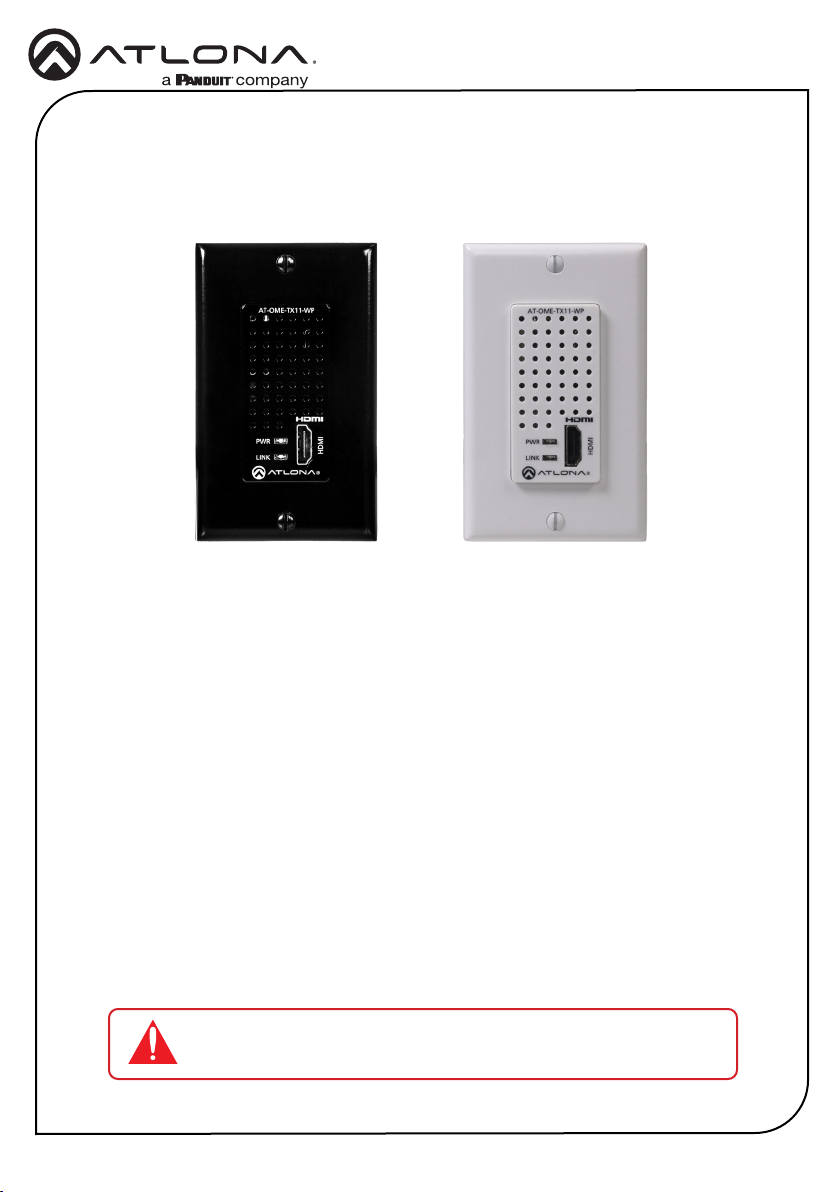
AT-OME-TX11-WP
Omega™ 4K/UHD
Wallplate Transmitter for HDMI with USB
AT-OME-TX11-WP
The Atlona AT-OME-TX11-WP is an HDBaseT transmitter for video up to 4K/60 4:2:0, plus
embedded audio over distances up to 330 feet (100 meters). It features a US one-gang, wallplate
form factor, and includes interchangeable black and white wallplates and faceplates. Part of the
Omega™ Series of integration products for modern AV communications and collaboration, the
OME-TX11-WP is HDCP 2.2 compliant and is remotely powered over HDBaseT. This transmitter
is ideal for use with Omega Series receivers as well as switchers with HDBaseT inputs.
Package Contents
1 x AT-OME-TX11-WP
1 x White faceplate
1 x White Decora® wallplate (US 1-gang)
1 x Black faceplate
1 x Black Decora® wallplate (US 1-gang)
2 x Mounting screws (course thread)
2 x Mounting screws (ne thread)
IMPORTANT: Visit http://www.atlona.com/product/AT-OME-TX11-WP
for the latest rmware updates and User Manual.
1
Page 2
Installation Guide
CAN ICES-003(A)
/NMB-00(A)
05
AT-OME-TX11-WP
AT-OME-TX11-WP
1
2
PWR
LINK
HDMI
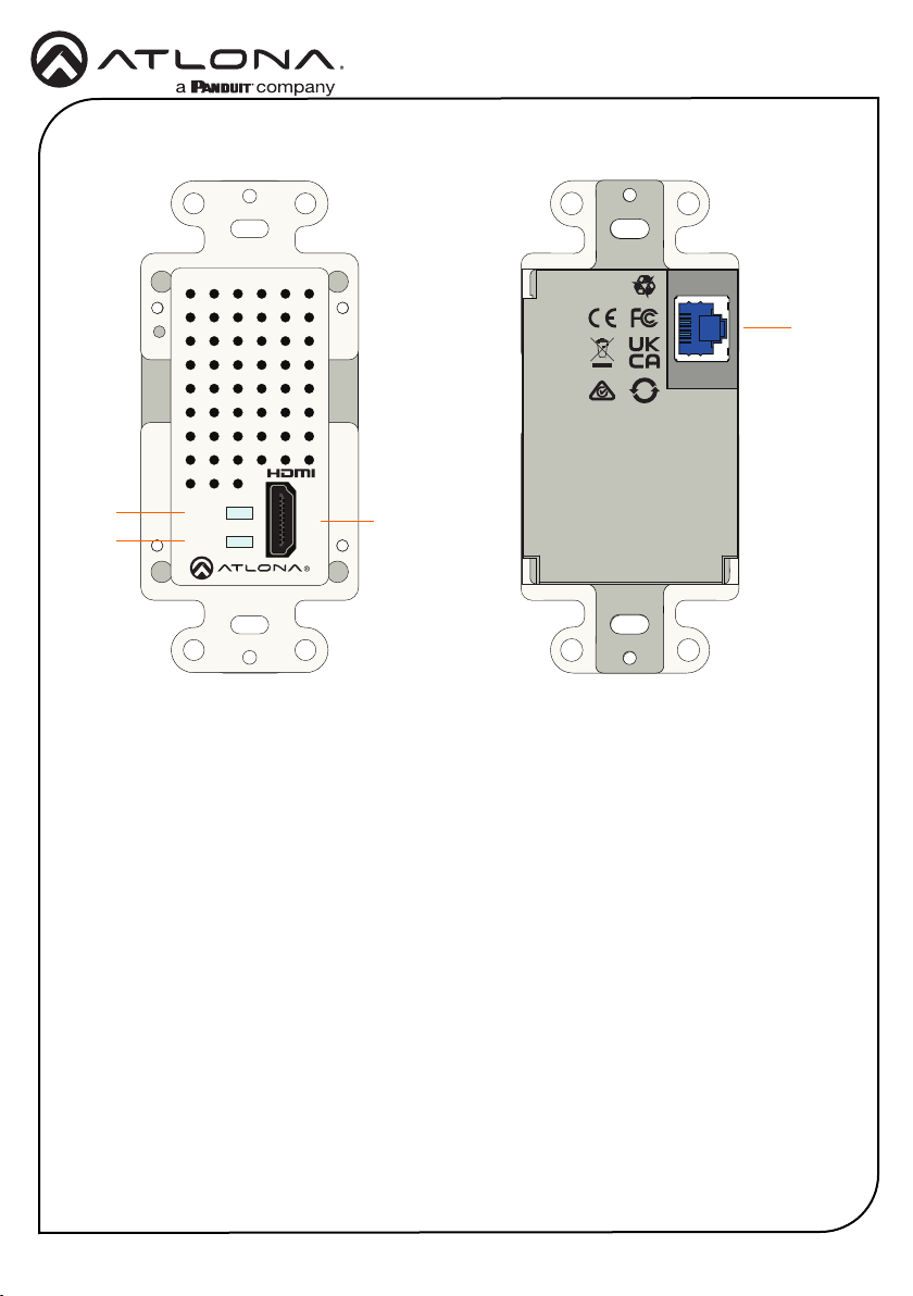
1 PWR
This LED indicator glows solid green
when the unit is powered. Refer to
LED Indicators (page 5) for more
information.
2 LINK
This LED indicator glows solid amber to
indicate that the HDBaseT signal integrity
is good. Refer to LED Indicators (page
5) for more information.
CAN ICES-003(A)
/NMB-00(A)
4
05
HDBaseT
OUT
3
3 HDMI
Connect an HDMI cable from this port to a
UHD/HD source.
4 HDBaseT OUT
Connect a category cable from this port
to the HDBaseT IN port of the AT-OMERX11 or other PoE-compatible receiver.
2
Page 3
Installation Guide
AT-OME-TX11-WP
Faceplate Removal and Assembly
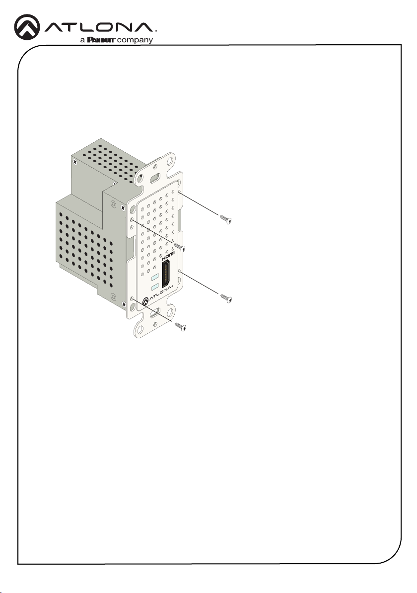
Removal of the faceplate requires that the AT-OME-TX11-WP be disassembled from the electrical
box or mud ring. A small Phillips-head screwdriver is required to remove the faceplate.
1. Unscrew the four Phillips-head screws from the sides of the faceplate, as shown:
AT-OME-TX11-WP
HDMI
PWR
LINK
2. Gently remove the faceplate by pulling it toward you.
3. Attach the new faceplate, then secure it using the four Phillips-head screws. Do not overtighten or apply high-torque devices to the screws. Doing so may damage the faceplate
and/or the screws.
4. Install the AT-OME-TX11-WP into the electrical box or mud ring.
5. Reattach the wallplate.
3
Page 4
Installation Guide
AT-OME-TX11-WP
Installation
1. Connect an HDMI cable from the UHD/HD source to the HDMI port.
2. Connect a category cable, from the HDBaseT OUT port on the rear of the AT-OME-TX11WP, to the HDBaseT IN port on the receiver.
Cable Recommendation Guidelines
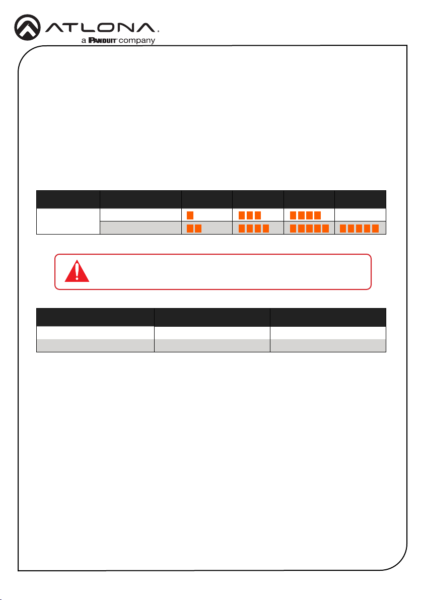
Refer to the tables below for recommended cabling when using Altona products with HDBaseT.
The green bars indicate the signal quality when using each type of cable. Higher-quality signals
are represented by more bars.
Core Shielding CAT5e CAT 6 CAT6a CAT 7
Solid UTP (unshielded) N/A
STP (shielded)
IMPORTANT: Stranded or patch cables are not recommended due to
performance issues.
Cable* Max. Distance @ 4K Max. Distance @ 1080p
CAT5e 295 feet (90 meters) 330 feet (100 meters)
CAT6 / CAT6a / CAT7 330 feet (100 meters) 330 feet (100 meters)
*Atlona recommends TIA/EIA 568-B termination for optimal performance.
4
Page 5
Installation Guide
LED Indicators
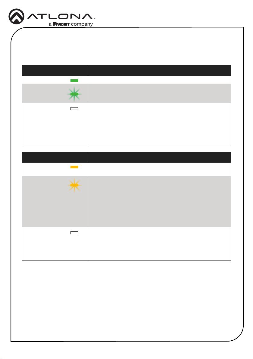
The PWR and LINK LED indicator on both the transmitter and receiver unit provides basic
information on the current status of the AT-OME-TX11-WP.
PWR Description
Solid green Unit is powered. Normal operating mode.
Blinking green Unit is in rmware update mode. Refer to Updating the
Firmware (page 6) for more information.
O Unit is not powered.
• Make sure that the category cable between the HDBaseT
IN port on the transmitter and the HDBaseT OUT port on
the receiver is secure.
• Make sure that the power supply, at the receiver, is
connected to an active AC outlet.
LINK Description
AT-OME-TX11-WP
Solid amber The link integrity between the transmitter and the receiver is
Blinking amber Poor signal integrity between the transmitter and the receiver.
O The link integrity between the transmitter and the receiver is
good.
• Make sure that the category cable between the HDBaseT
IN port on the transmitter and the HDBaseT OUT port on
the receiver is secure.
• The category cable may be compromised. Try using a
dierent category cable. Make sure that the cable is solid
core. Stranded or patch cables are not recommended.
compromised.
• Check the category cable between the HDBaseT IN port
on the transmitter and the HDBaseT OUT port on the
receiver.
5
Page 6
Installation Guide
AT-OME-TX11-WP
Updating the Firmware
Requirements:
• AT-OME-TX11-WP
• Firmware le
• Computer running Windows
• USB-A to USB-C cable or USB-C to USB-C cable
NOTE: The update process can take up to ve minutes to complete.
1. Disconnect power from the unit.
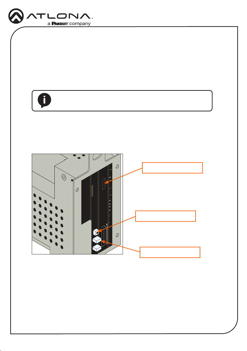
2. Remove the faceplate to access the hidden “rmware update” button, located above the
PWR LED indicator. Refer to Faceplate Removal and Assembly (page 3) for more
information.
USB-C port
Firmware update button
PWR LED indicator
3. Connect the USB cable between the PC and the USB-C port on the unit.
4. Simultaneously press and hold the rmware update button, while reconnecting the power.
The PWR LED indicator will be blinking green.
6
Page 7
Installation Guide
AT-OME-TX11-WP
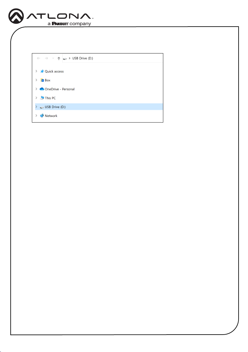
5. The USB Drive folder will be displayed. If this folder is not displayed, automatically, select
the USB Drive drive from Windows Explorer.
6. Delete all les from the USB Drive, if any are present.
7. Drag-and-drop the rmware le to the drive.
8. The PWR LED indicator, on the front panel, will ash green while the unit is being updated.
Do not disconnect the USB cable during the update process. When the PWR LED stops
ashing and is solid green, the update process will be complete.
7
Page 8
Warranty
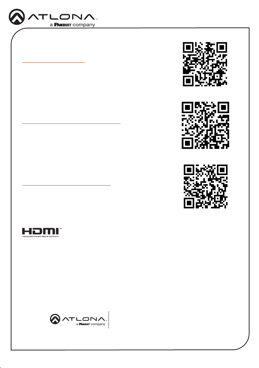
To view the product warranty, use the following link or QR code:
https://atlona.com/warranty/.
English Declaration of Conformity
The English version can be found under the resources tab at:
https://atlona.com/product/at-ome-tx11-wp/.
Chinese Declaration of Conformity 中国RoHS合格声明
由SKU列出於:
https://atlona.com/about-us/china-rohs/.
Installation Guide
AT-OME-TX11-WP
®
The terms HDMI, HDMI High-Denition Multimedia Interface, HDMI trade dress and the HDMI Logos are
trademarks or registered trademarks of HDMI Licensing Administrator, Inc.
US International
atlona.com • 408.962.0515 • 41.43.508.4321
© 2024 Atlona Inc. All rights reserved. “Atlona” and the Atlona logo are registered trademarks of Atlona Inc. All other brand names and trademarks or registered
trademarks are the property of their respective owners. Pricing, specications and availability subject to change without notice. Actual products, product images, and
online product images may vary from images shown here.
8
25355-R1
 Loading...