

Page 1
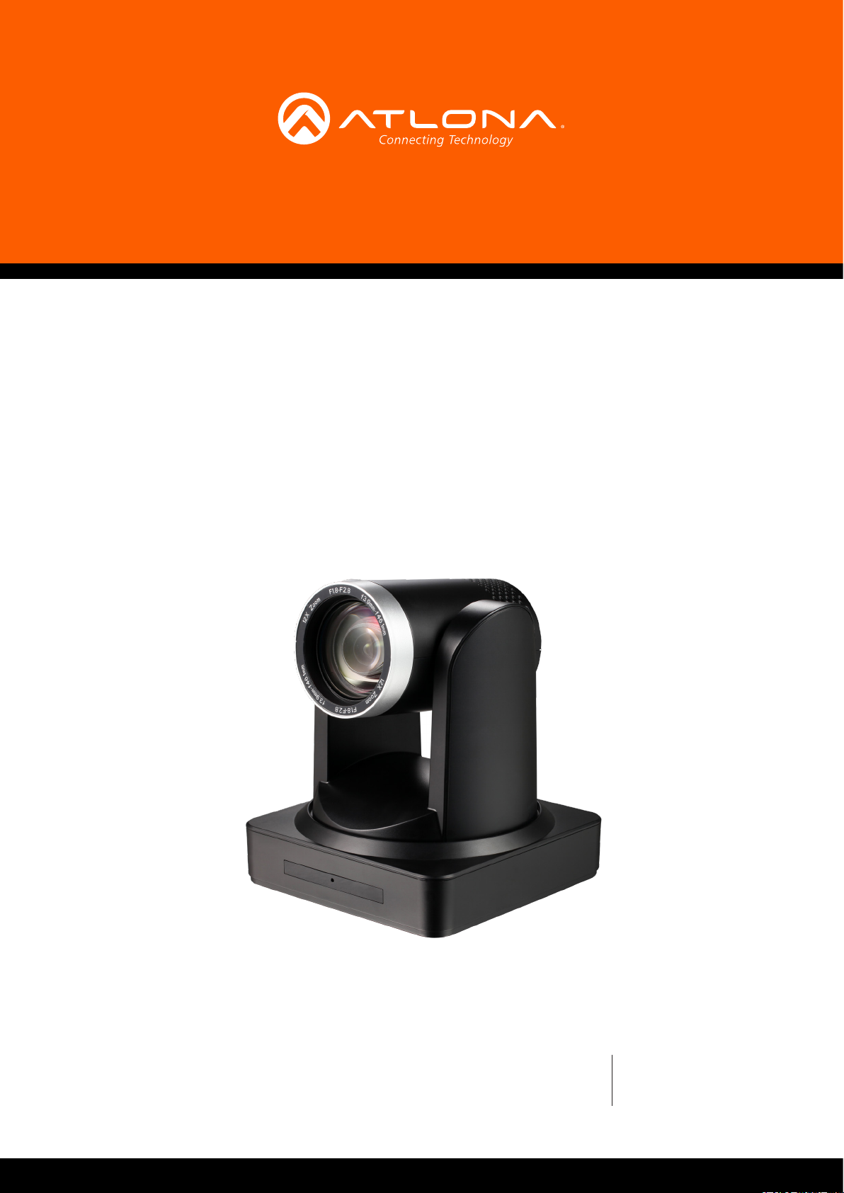
PTZ Camera
for HDVS-300 Soft Codec Conferencing System
AT-HDVS-CAM
Atlona Manuals
PTZ Camera
Page 2

Version Information
Version Release Date Notes
1 10/17 Initial release
AT-OMNI-232
2
Page 3

Welcome to Atlona!
Thank you for purchasing this Atlona product. We hope you enjoy it and will take an extra few moments to register
your new purchase.
Registration only takes a few minutes and protects this product against theft or loss. In addition, you will receive
notications of product updates and rmware. Atlona product registration is voluntary and failure to register will not
aect the product warranty.
To register your product, go to http://www.atlona.com/registration
Sales, Marketing, and Customer Support
Main Oce
Atlona Incorporated
70 Daggett Drive
San Jose, CA 95134
United States
Oce: +1.877.536.3976 (US Toll-free)
Oce: +1.408.962.0515 (US/International)
Sales and Customer Service Hours
Monday - Friday: 6:00 a.m. - 4:30 p.m. (PST)
http://www.atlona.com/
International Headquarters
Atlona International AG
Ringstrasse 15a
8600 Dübendorf
Switzerland
Oce: +41 43 508 4321
Sales and Customer Service Hours
Monday - Friday: 09:00 - 17:00 (UTC +1)
Operating Notes
As of this writing, there are no rmware updates for this product. When new rmware is released, update instructions
will be included with the rmware and will be appended to this manual.
IMPORTANT: Visit http://www.atlona.com/product/AT-HDVS-CAM for the latest rmware updates
and User Manual.
AT-OMNI-232
3
Page 4

Atlona, Inc. (“Atlona”) Limited Product Warranty
Coverage
Atlona warrants its products will substantially perform to their published specications and will be free from defects
in materials and workmanship under normal use, conditions and service.
Under its Limited Product Warranty, Atlona, at its sole discretion, will either:
• repair or facilitate the repair of defective products within a reasonable period of time, restore products to their
proper operating condition and return defective products free of any charge for necessary parts, labor and
shipping.
OR
• replace and return, free of charge, any defective products with direct replacement or with similar products
deemed by Atlona to perform substantially the same function as the original products.
OR
• refund the pro-rated value based on the remaining term of the warranty period, not to exceed MSRP, in cases
where products are beyond repair and/or no direct or substantially similar replacement products exist.
Repair, replacement or refund of Atlona products is the purchaser’s exclusive remedy and Atlona liability does not
extend to any other damages, incidental, consequential or otherwise.
This Limited Product Warranty extends to the original end-user purchaser of Atlona products and is non-transferrable
to any subsequent purchaser(s) or owner(s) of these products.
Coverage Periods
Atlona Limited Product Warranty Period begins on the date of purchase by the end-purchaser. The date contained on
the end-purchaser ‘s sales or delivery receipt is the proof purchase date.
Limited Product Warranty Terms – New Products
• 10 years from proof of purchase date for hardware/electronics products purchased on or after June 1, 2013.
• 3 years from proof of purchase date for hardware/electronics products purchased before June 1, 2013.
• Lifetime Limited Product Warranty for all cable products.
Limited Product Warranty Terms – Refurbished (B-Stock) Products
• 3 years from proof of purchase date for all Refurbished (B-Stock) hardware and electronic products purchased
on or after June 1, 2013.
Remedy
Atlona recommends that end-purchasers contact their authorized Atlona dealer or reseller from whom they
purchased their products. Atlona can also be contacted directly. Visit www.atlona.com for Atlona’s contact
information and hours of operation. Atlona requires that a dated sales or delivery receipt from an authorized dealer,
reseller or end-purchaser is provided before Atlona extends its warranty services. Additionally, a return merchandise
authorization (RMA) and/or case number, is required to be obtained from Atlona in advance of returns.
Atlona requires that products returned are properly packed, preferably in the original carton, for shipping. Cartons not
bearing a return authorization or case number will be refused. Atlona, at its sole discretion, reserves the right to reject
any products received without advanced authorization. Authorizations can be requested by calling 1-877-536-3976
(US toll free) or 1-408- 962-0515 (US/international) or via Atlona’s website at www.atlona.com.
Exclusions
This Limited Product Warranty excludes:
• Damage, deterioration or malfunction caused by any alteration, modication, improper use, neglect, improper
packaging or shipping (such claims must be presented to the carrier), lightning, power surges, or other acts of
nature.
AT-OMNI-232
4
Page 5

Atlona, Inc. (“Atlona”) Limited Product Warranty
• Damage, deterioration or malfunction resulting from the installation or removal of this product from any
installation, any unauthorized tampering with this product, any repairs attempted by anyone unauthorized by
Atlona to make such repairs, or any other cause which does not relate directly to a defect in materials and/or
workmanship of this product.
• Equipment enclosures, cables, power supplies, batteries, LCD displays, and any accessories used in conjunction
with the product(s).
• Products purchased from unauthorized distributors, dealers, resellers, auction websites and similar unauthorized
channels of distribution.
Disclaimers
This Limited Product Warranty does not imply that the electronic components contained within Atlona’s products
will not become obsolete nor does it imply Atlona products or their electronic components will remain compatible
with any other current product, technology or any future products or technologies in which Atlona’s products may
be used in conjunction with. Atlona, at its sole discretion, reserves the right not to extend its warranty oering in
instances arising outside its normal course of business including, but not limited to, damage inicted to its products
from acts of god.
Limitation on Liability
The maximum liability of Atlona under this limited product warranty shall not exceed the original Atlona MSRP for
its products. To the maximum extent permitted by law, Atlona is not responsible for the direct, special, incidental or
consequential damages resulting from any breach of warranty or condition, or under any other legal theory. Some
countries, districts or states do not allow the exclusion or limitation of relief, special, incidental, consequential or
indirect damages, or the limitation of liability to specied amounts, so the above limitations or exclusions may not
apply to you.
Exclusive Remedy
To the maximum extent permitted by law, this limited product warranty and the remedies set forth above are
exclusive and in lieu of all other warranties, remedies and conditions, whether oral or written, express or implied.
To the maximum extent permitted by law, Atlona specically disclaims all implied warranties, including, without
limitation, warranties of merchantability and tness for a particular purpose. If Atlona cannot lawfully disclaim
or exclude implied warranties under applicable law, then all implied warranties covering its products including
warranties of merchantability and tness for a particular purpose, shall provide to its products under applicable law.
If any product to which this limited warranty applies is a “Consumer Product” under the Magnuson-Moss Warranty
Act (15 U.S.C.A. §2301, ET SEQ.) or other applicable law, the foregoing disclaimer of implied warranties shall not
apply, and all implied warranties on its products, including warranties of merchantability and tness for the particular
purpose, shall apply as provided under applicable law.
Other Conditions
Atlona’s Limited Product Warranty oering gives legal rights, and other rights may apply and vary from country to
country or state to state. This limited warranty is void if (i) the label bearing the serial number of products have been
removed or defaced, (ii) products are not purchased from an authorized Atlona dealer or reseller. A comprehensive
list of Atlona’s authorized distributors, dealers and resellers can be found at www.atlona.com.
AT-OMNI-232
5
Page 6

Important Safety Information
CAUTION
RISK OF ELECTRIC SHOCK
DO NOT OPEN
CAUTION: TO REDUCT THE RISK OF
DO NOT OPEN ENCLOSURE OR EXPOSE
The exclamation point within an equilateral triangle is intended to alert the user to
the presence of important operating and maintenance instructions in the literature
accompanying the product.
The information bubble is intended to alert the user to helpful or optional operational instructions in the literature accompanying the product.
ELECTRIC SHOCK
TO RAIN OR MOISTURE.
NO USER-SERVICEABLE PARTS
INSIDE REFER SERVICING TO
QUALIFIED SERVICE PERSONNEL.
1. Read these instructions.
2. Keep these instructions.
3. Heed all warnings.
4. Follow all instructions.
5. Do not use this product near water.
6. Clean only with a dry cloth.
7. Do not block any ventilation openings. Install in
accordance with the manufacturer’s instructions.
8. Do not install or place this product near any heat
sources such as radiators, heat registers, stoves, or
other apparatus (including ampliers) that produce
heat.
9. Do not defeat the safety purpose of a polarized
or grounding-type plug. A polarized plug has two
blades with one wider than the other. A grounding
type plug has two blades and a third grounding
prong. The wide blade or the third prong are
provided for your safety. If the provided plug does
not t into your outlet, consult an electrician for
replacement of the obsolete outlet.
10. Protect the power cord from being walked on
or pinched particularly at plugs, convenience
receptacles, and the point where they exit from the
product.
11. Only use attachments/accessories specied by
Atlona.
12. To reduce the risk of electric shock and/or damage
to this product, never handle or touch this unit or
power cord if your hands are wet or damp. Do not
expose this product to rain or moisture.
13. Unplug this product during lightning storms or when
unused for long periods of time.
14. Refer all servicing to qualied service personnel.
Servicing is required when the product has been
damaged in any way, such as power-supply cord or
plug is damaged, liquid has been spilled or objects
have fallen into the product, the product has been
exposed to rain or moisture, does not operate
normally, or has been dropped.
FCC Statement
FCC Compliance and Advisory Statement: This hardware device complies with
Part 15 of the FCC rules. Operation is subject to the following two conditions: 1)
this device may not cause harmful interference, and 2) this device must accept any
interference received including interference that may cause undesired operation. This
equipment has been tested and found to comply with the limits for a Class A digital
device, pursuant to Part 15 of the FCC Rules. These limits are designed to provide
reasonable protection against harmful interference in a commercial installation.
This equipment generates, uses, and can radiate radio frequency energy and, if not
installed or used in accordance with the instructions, may cause harmful interference
to radio communications. However there is no guarantee that interference will not occur in a particular installation. If
this equipment does cause harmful interference to radio or television reception, which can be determined by turning
the equipment o and on, the user is encouraged to try to correct the interference by one or more of the following
measures: 1) reorient or relocate the receiving antenna; 2) increase the separation between the equipment and the
receiver; 3) connect the equipment to an outlet on a circuit dierent from that to which the receiver is connected;
4) consult the dealer or an experienced radio/TV technician for help. Any changes or modications not expressly
approved by the party responsible for compliance could void the user’s authority to operate the equipment. Where
shielded interface cables have been provided with the product or specied additional components or accessories
elsewhere dened to be used with the installation of the product, they must be used in order to ensure compliance
with FCC regulations.
AT-OMNI-232
6
Page 7

Table of Contents
Introduction 8
Features 8
Package Contents 8
Panel Description 9
Installation 10
Connection Instructions 10
Mounting Instructions 10
Connection Diagram 12
WebGUI 13
Visca Protocol List 20
Camera Return Command 20
Camera Control Command 20
Inquiry Command 24
Pelco-D Protocol Command List 28
Pelco-P Protocol Command List 29
Appendix 30
Specications 30
Index 31
AT-OMNI-232
7
Page 8

Introduction
The Atlona AT-HDVS-CAM is an enterprise-grade PTZ camera designed for use with the AT-UHD-HDVS-300-KIT
in soft codec conferencing applications. It features a USB interface for video and camera control. The HDVS-CAM
seamlessly integrates with the HDVS-300-KIT for a complete, automated conferencing system that includes AV
and USB extension, plus automatic input selection and display powering when a PC is connected. The HDVS-CAM
delivers high performance, professional-quality imaging with video resolutions up to 1080p @ 30 Hz, as well as fast
and accurate auto-focusing, and a fast yet quiet pan and tilt mechanism. This PTZ camera is ideal for a wide range of
small to medium-sized meeting spaces, classrooms, and training rooms.
Features
• Available video resolutions from 176x144 up to 1080p @ 30 Hz
• Fast and accurate auto focus, plus auto white balance and auto exposure modes
• Fast and quiet pan and tilt mechanism
• USB 2.0 interface for video and camera control
• Multi-element zoom lens with 10x optical zoom and a 60.9° horizontal eld of view
• Picture controls available for brightness, color, saturation, contrast, sharpness, and gamma
• TCP/IP, RS-232, USB, and IR control – convenient handheld IR remote control included
• High performance imaging, ne detail, and color rendering with 1/2.8” low-noise, HD CMOS sensor
Package Contents
1 x AT-HDVS-CAM
1 x Wall mounting plate
4 x Mounting screws
1 x IR Remote Control
1 x USB A cable
1 x VISCA to RS-232 DB-9 adapter
1 x AAA battery
1 x Installation Guide
AT-OMNI-232
8
Page 9
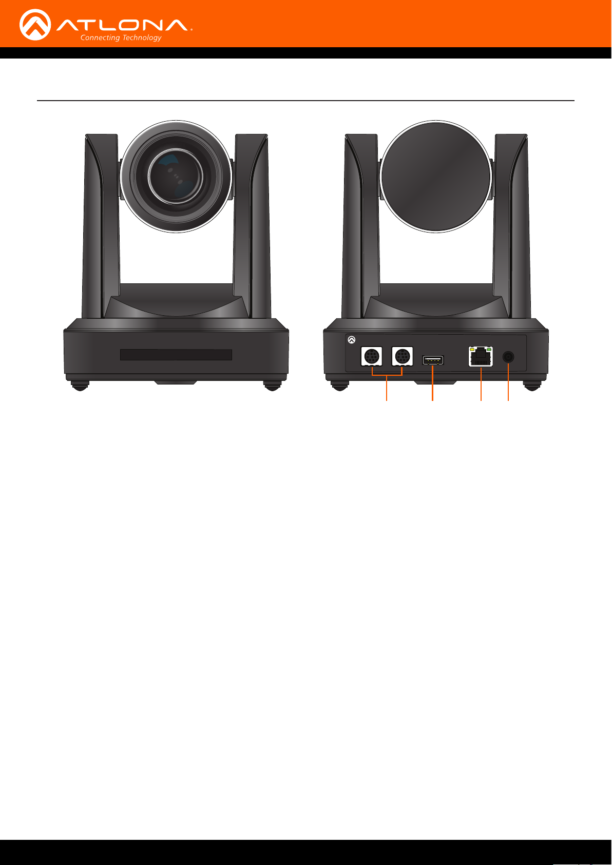
Panel Description
3
F
-
6
.
1
F
m
o
o
Z
X
0
1
m
m
7
4
f
-
m
m
7
.
4
f
0
.
0
f
4
.
7
m
m
-
f
4
7
m
m
1
0
X
Z
o
o
m
F
1
.
6
-
F
3
.
LAN
OUT
USB
USB
RS-232
IN
DC 12V
AT-HDVS-CAM
1. RS-232
Connect included VISCA to RS-232 adapter here
to control the camera with a third party software or
hardware controller.
2. USB
Connect USB A cable to this port from the USB port
of the AT-UHD-HDVS-300-RX.
1 2
3 4
3. LAN
Connect to a network switch to control the unit via
TCP/IP or webGUI.
4. DC 12V
Connect the included 12V power supply to this port.
AT-OMNI-232
9
Page 10
Installation
RXD
RI
RTS
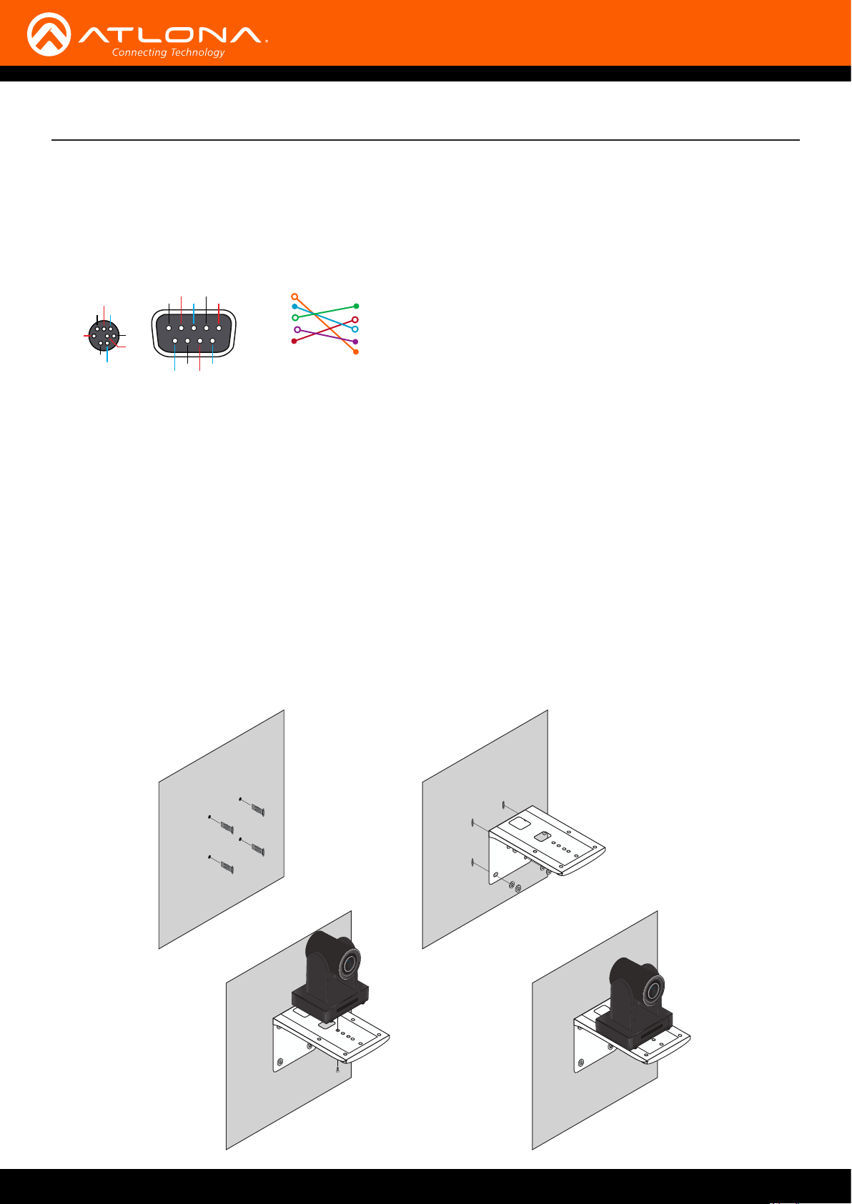
Connection Instructions
1. Connect the Ethernet cable to the LAN port on the back of the AT-HDVS-CAM.
2. Connect the USB cable to the AT-UHD-HDVS-300-RX.
3. *Optional* Connect the Visca to RS-232 cable to the Visca port for RS-232 control.
RXD
Visca
IR OUT
NC
GND
TXD
RS-232
DSR
TXD
GND
DCD
GND
DSR
DTR
DSR
CTS
4. Connect the DC 12V power cable to the unit.
The AT-HDVS-CAM has two installation options, wall mount (included) and ceiling mount (purchased separately).
Wall Mount installation
Visca
DTR
DSR
TXD
GND
RXD
GND
IR OUT
NC
RS-232
DCD
RXD
TXD
DTR
GND
DSR
RTS
CTS
RI
Mounting Instructions
The install the AT-HDVS-CAM, 4 M6 swelling bolts, 1 1/4 20UNC bolt, 4 M6 nuts & shims, the included wall mount
bracket, and the AT-HDVS-CAM are needed.
1. Install the M6 swelling bolts in a rectangular pattern on the wall, 100 mm wide and 50 mm high.
2. Attached the wall mount bracket onto the wall, by placing them on the M6 swelling bolts and securing it with the
M6 nuts and shims.
3. Once the wall mount bracket is secure on the wall, place the camera on the top of the wall mount bracket and
secure it with the 1/4 20UNC bolt.
f
4
.
0
7
.
3
m
F
m
-
6
-
.
f
1
F
4
7
m
m
m
o
o
Z
X
0
1
m
m
1
7
0
X
4
f
Z
o
-
o
0
m
.
3
F
F
-
1
.
6
f
4
.
0
7
.
3
m
F
m
-
6
-
.
f
1
F
4
7
m
m
m
o
o
Z
X
0
1
m
m
1
7
0
X
4
f
Z
o
-
o
0
m
.
3
F
F
-
1
.
6
AT-OMNI-232
10
Page 11
Installation
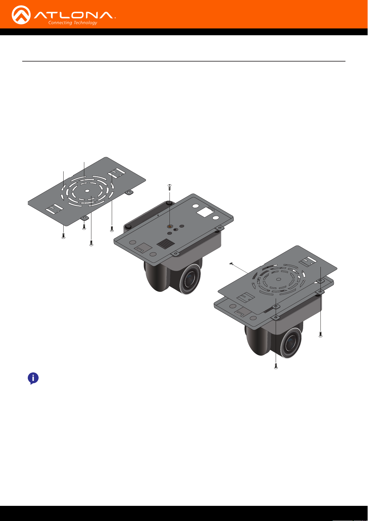
Ceiling Mount installation
To install the AT-HDVS-CAM, 4 PA3X30 self-tapping screws, 4 PM3X6 screws, 4 screw stoppers, 1 1/4 20UNC
screw, the optional ceiling upper and lower covering plates, and the AT-HDVS-CAM are needed.
1. Install the 4 screw stoppers in the ceiling.
2. Connect the upper ceiling covering plate to the screw stoppers using the PA3X30 self-tapping screws.
3. Connect the lower ceiling covering plate to the bottom of the AT-HDVS-CAM using the 1/4 20UNC screw.
4. Mount the lower ceiling covering plate to the upper ceiling plate using 3 PM3X6 bolts.
1 2
ON KE
1 2
ON KE
NOTE: The camera picture will need to be inverted for video to be viewed correctly. View the AT-HDVS-CAM
manual for instructions on how to invert video.
AT-OMNI-232
11
Page 12
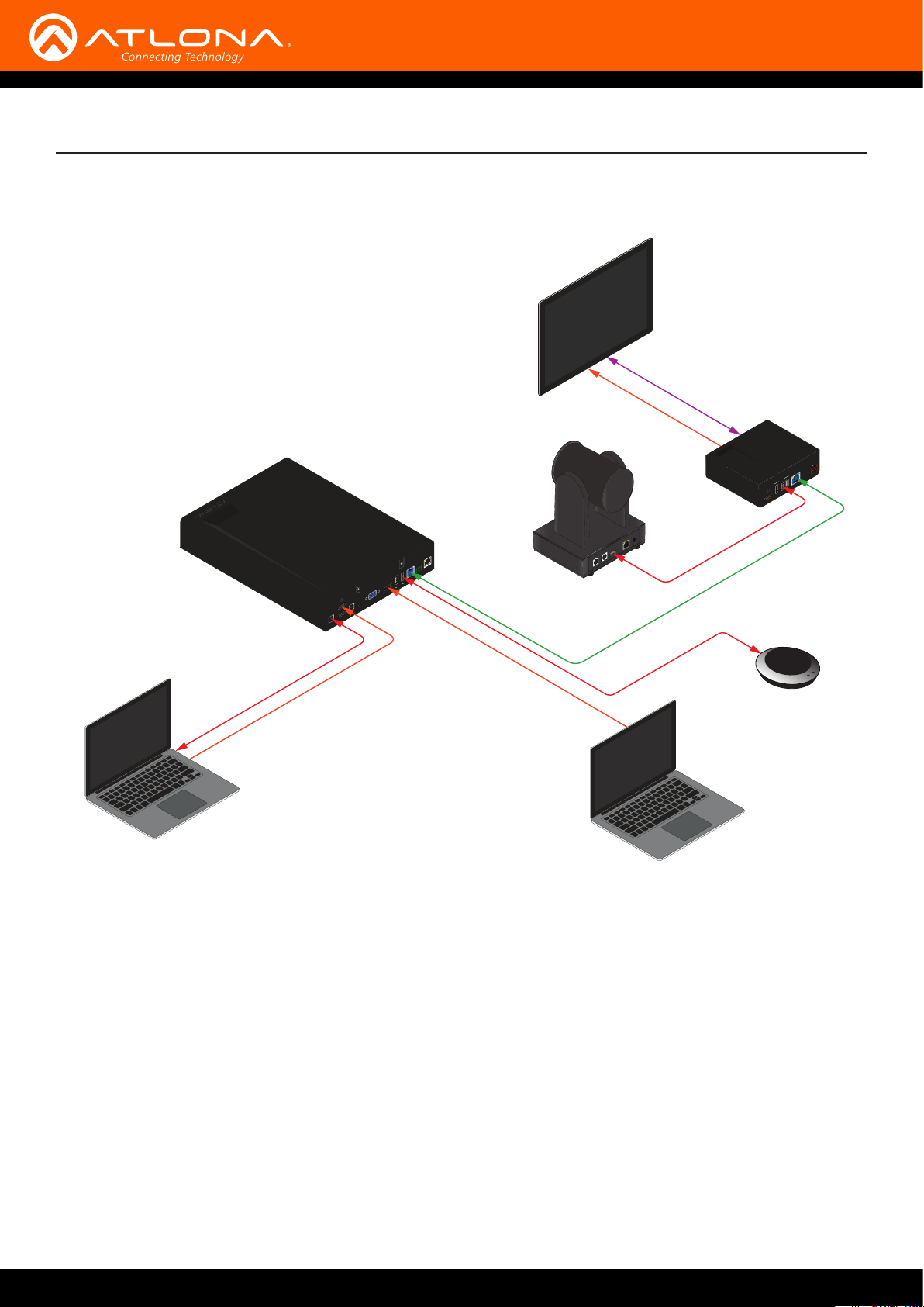
AT-UHD-HDVS-300-TX
Connection Diagram
RXTX
LAN
USB
USB
USB HUB HDBaseT OUT RS-232
HDMI IN 1
USB 2USB 1 AUDIO VGA IN DP IN 4
HDMI IN 2
Display
AT-HDVS-CAM
Installation
Control
AT-HDVS-CAM
HDMI
+
USB HUB HDBaseT IN DC 48V
USB
USB
HDMI IN 5
USB
AT-UHD-HDVS-300-RX
DC 12V
LAN
USB
USB
OUT
RS-232
IN
USB
HDBaseT
Laptop
USB
HDMI
DisplayPort
USB
Speakerphone
Laptop
AT-OMNI-232
12
Page 13
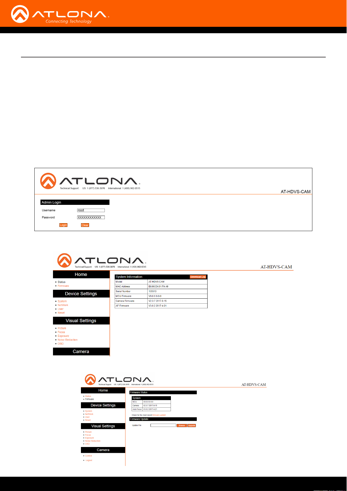
WebGUI
The AT-HDVS-CAM includes a built-in webGUI, which allows easy management and control of all features. Follow
the instructions below to access the webGUI.
1. Use an IP scanner to determine the IP address of the AT-HDVS-CAM. The default IP address is printed on an
adhesive label, attached to the bottom of the camera base. Each camera has a unique default IP address.
2. Launch a web browser.
3. In the address bar, type the IP address of the AT-HDVS-CAM.
4. Enter the following information on the Login page.
Login: root
Password: Atlona
5. Click the Login button.
6 The status page will display, giving all the general information of the AT-HDVS-CAM.
7 Select rmware from the side menu.
AT-OMNI-232
13
Page 14
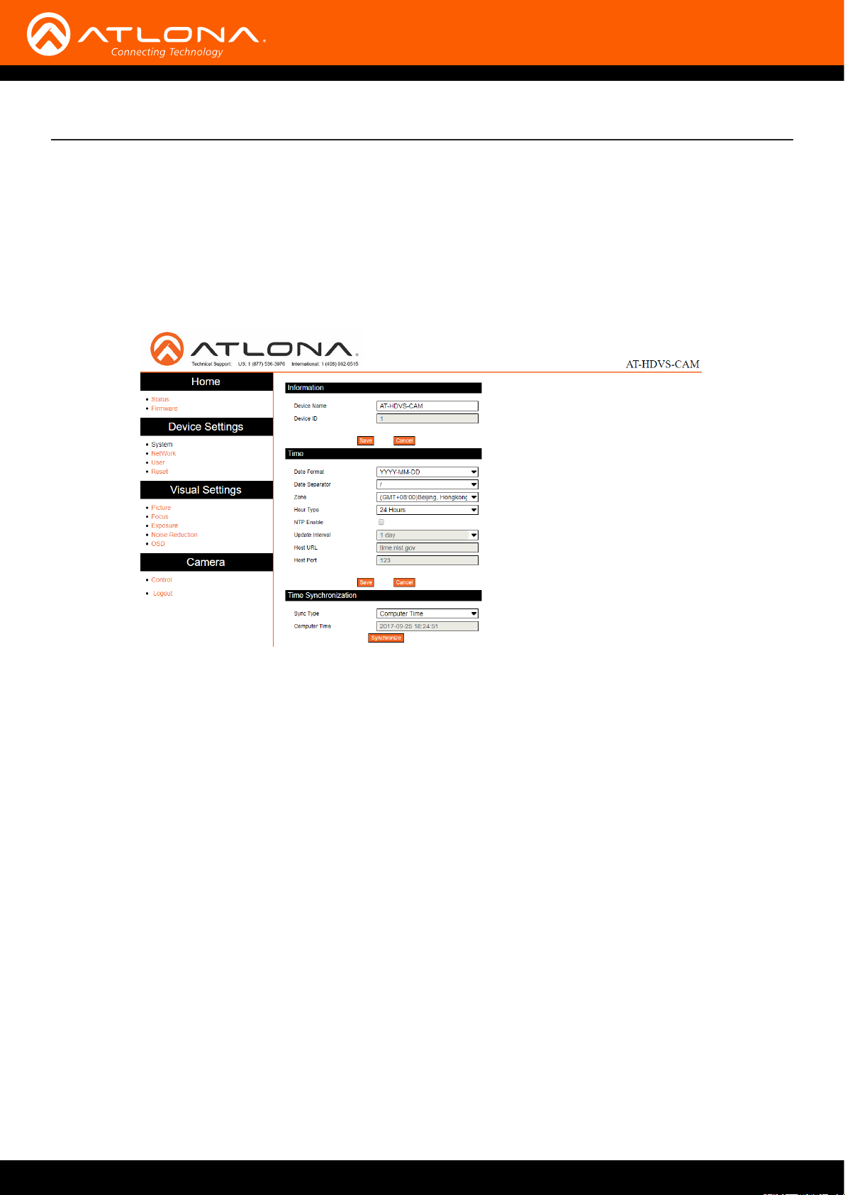
System
MCU - Displays the current OSD software.
Camera - Displays the current unit software.
Auto Focus - Displays the software for auto focus.
Firmware Update
Browse - Select browse and search the local computer for the rmware.
Update - Load the selected le to the unit.
webGUI
Information
Device Name - Displays the SKU of the unit.
Device ID - Displays the ID of the AT-HDVS-CAM.
Time
Date Format - Select how the date will display on video and saved les.
Date Separator - Select the symbol to display between date format.
Zone - Select the time zone for the camera.
Hour Type - Select the way the time displays through the day.
NTP Enable - Enable or disable time synchronization.
Update Interval - Decide the amount of time between synchronizations.
Host URL - The unit will synchronize to the time of the url typed in this eld.
Host Port - Type the port to ensure communication between the camera and the host URL.
Time Synchronization
Sync Type - Decide the device the camera will sync to.
Computer Time - Displays the current time of the selected synchronization type.
8 Select network from the side menu.
AT-OMNI-232
14
Page 15
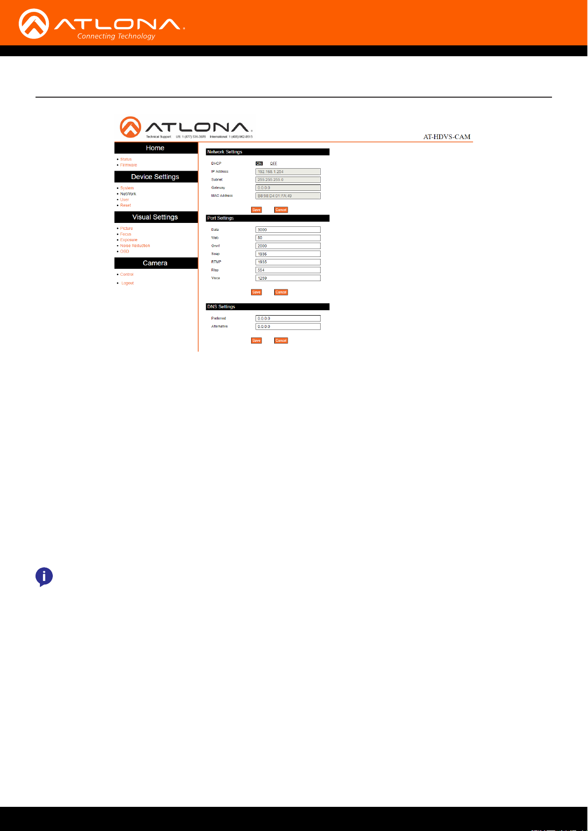
webGUI
Network Settings
DHCP - Switch between DHCP (ON) and static (OFF).
IP Address, Subnet, Gateway - This will display the current IP settings on DHCP. When set to static, ll in the IP
address, netmask, gateway, and telnet port.
MAC Address - Displays the MAC Address of the AT-HDVS-CAM.
Port Settings
Data port - Set to a value between 0 and 65535. Default is 3000.
Web Port - Set to a value between 0 and 65535. Default is 80.
Onvif Port - Set to a value between 0 and 65535. Default is 2000.
Soap Port - Set to a value between 0 and 65535. Default is 1936.
RTMP Port - Set to a value between 0 and 65535. Default is 1935.
RTSP Port - Set to a value between 0 and 65535. Default is 554.
Visca Port - Set to a value between 0 and 65535. Default is 3001.
NOTE: The AT-HDVS-CAM will restart automatically after the save button is pressed.
DNS Settings
Preferred - Set the preferred DNS server. Default is 0.0.0.0.
Alternative - Set the alternate DNS server. Default is 0.0.0.0.
9 Select User from the side menu.
AT-OMNI-232
15
Page 16
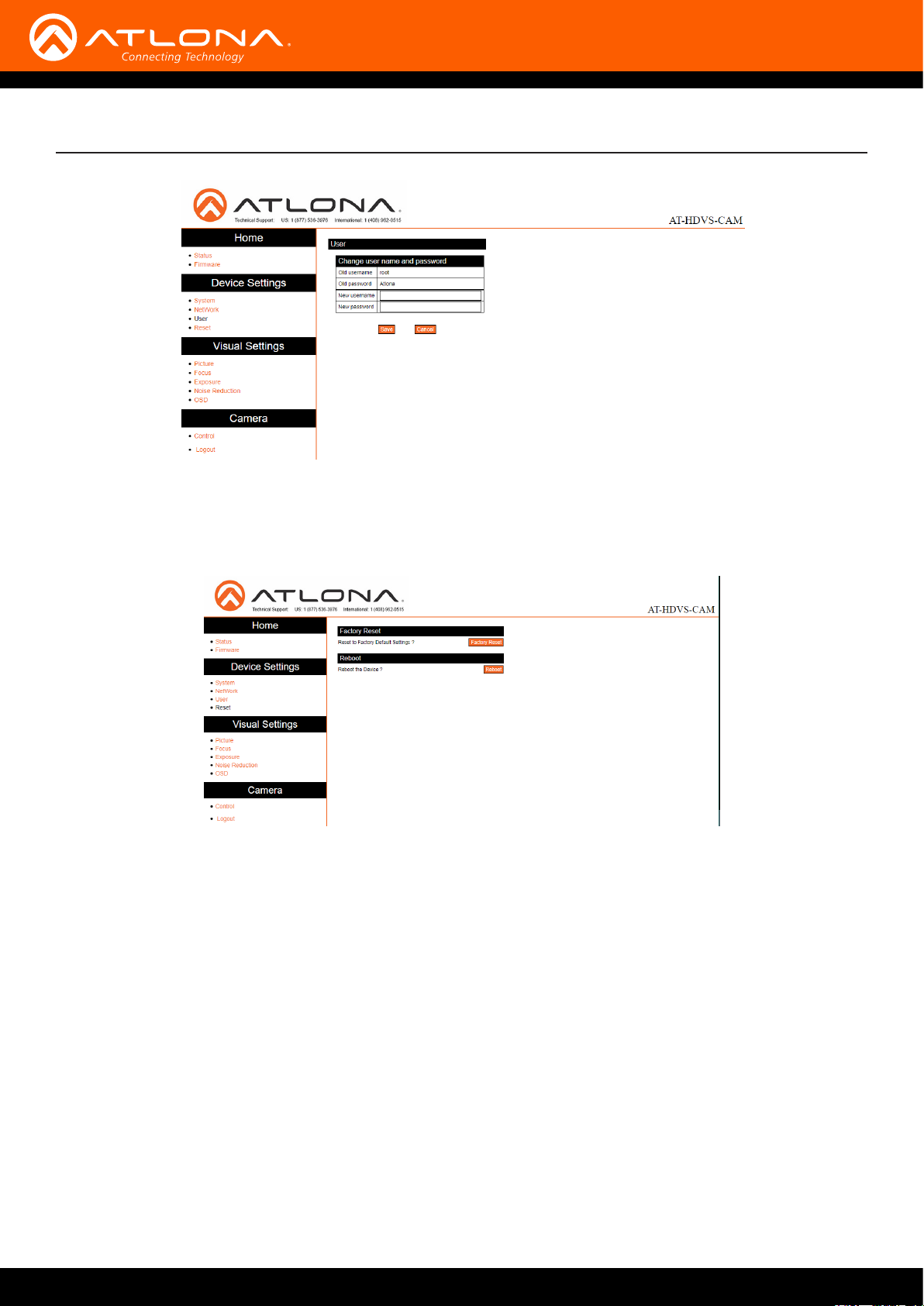
User
Update the username and password of the AT-HDVS-CAM webGUI.
10 Select Reset from the side menu.
webGUI
Factory Reset
Factory Reset - Sets the device back to the original factory settings.
Reboot
Reboot - Reboots the AT-HDVS-CAM.
11 Select Picture from the side menu.
AT-OMNI-232
16
Page 17
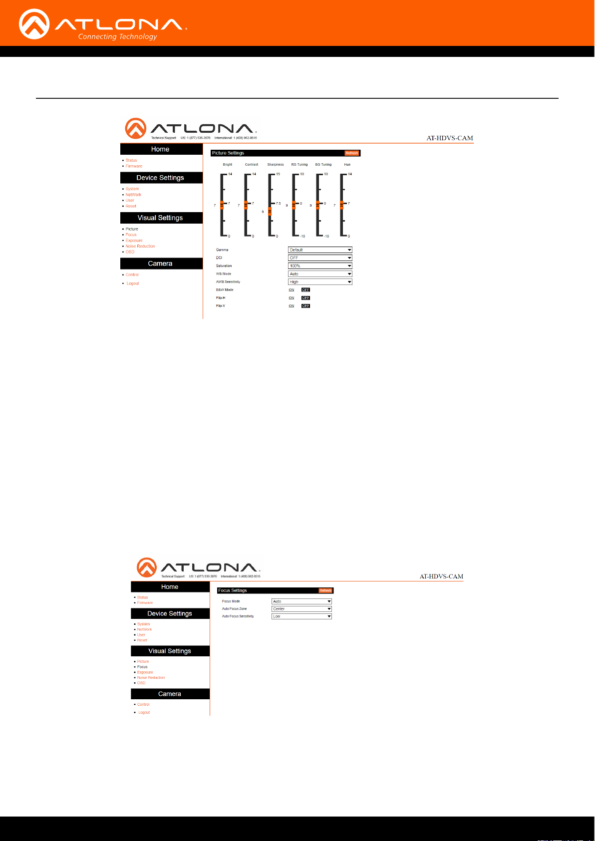
webGUI
Picture Settings
Brightness - Set to a value between 0 and 14. Default is 6.
Contrast - Set to a value between 0 and 14. Default is 8.
Sharpness - Set to a value between 0 and 15. Default is 7.
Gamma - Set the gamma value of the camera. Values are default, 0.45, 0.50, 0.52, and 0.55.
DCI (Dynamic Contrast Improvement) - Set to a value between 1 and 8 or OFF.
Saturation - Set to a value between 60% and 200%. Default is 80%.
WB Mode - Select between Auto, 3000K, 3500K, 4000K, 4500K, 5000K, 5500K, 6000K, 6500K, 7000K, Manu-
al, and OnePush.
AWB Sensitivity - Select between low, middle, and high.
B & W Mode - Toggle color between black and white (ON) and color (OFF). Default is o.
Flip-H - Flip the picture horizontally. Default is o.
Flip-V - Flip the picture vertically. Default is o.
12 Select Focus from the side menu.
Focus Settings
Focus Mode - Switch between Auto, Manual, or OnePush.
Auto Focus Zone - Switch the zone between Top, Center, Bottom, and All.
Auto Focus Sensitivity - Switch between High, Middle, and Low.
13 Select Exposure from the side menu.
AT-OMNI-232
17
Page 18
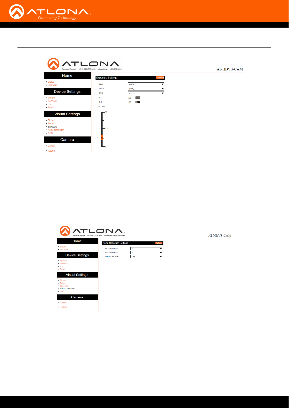
Exposure Settings
Mode - Switch between Auto, Manual, SAE, AAE, and Bright.
Flicker - Switch between OFF, 50Hz, and 60Hz.
DRC (Dynamic Range) - Set to a value between 1 and 8, or OFF.
EV (Exposure Compensation) - Toggle EV on and o.
BLC (Backlight Compensation) - Toggle backlight compensation on and o.
G.Limit (Gain Limit) - Set to a value between 0 and 15. Default is 3.
webGUI
14 Select Noise Reduction from the side menu.
Noise Reduction Settings
NR-2D Reduction - Set to a value between OFF, 1 and 7, or Auto.
NR-3D Reduction - Set to a value between OFF, 1 and 8.
Dynamic Hot Pixel - Set to a value between 1 and 5, or OFF.
15 Select OSD from the side menu.
AT-OMNI-232
18
Page 19
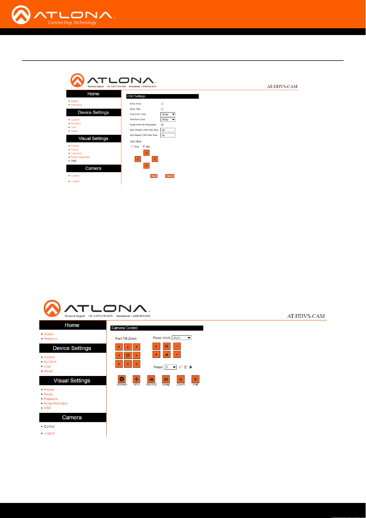
OSD Settings
Show Time - Toggle the time on and o on the on screen display.
Show Title - Toggle the title on and o on the on screen display.
Time Font Color - Set the time’s font color. Values are White, Black, Yellow, Red, and Blue.
Title Font Color - Set the time’s font color. Values are White, Black, Yellow, Red, and Blue.
Scale Font with Resolution - Toggle the font scaling on and o.
Main Stream OSD Font Size - Set the font size between 8 and 200.
Sub Stream OSD Font Size - Set the font size between 8 and 200.
OSD Oset - Use the buttons to position the OSD information on the screen.
webGUI
16 Select Control from the side menu.
Camera Control
Pan-Tilt-Zoom - Use the buttons to adjust the camera’s view and position.
Focus Mode - Switch between Auto, Manual, and OnePush. Use the buttons to adjust the focus.
Preset - Set the current position settings to a preset and save.
Video buttons - Adjust video settings with these buttons.
AT-OMNI-232
19
Page 20

Visca Protocol List
Camera Return Command
ACK/Completion Message
Command packet Note
ACK z0 41 FF Returned when the command is accepted
Completion z0 51 FF Returned when the command has been executed
z = camera address +8
Error Messages
Command packet Note
Syntax Error z0 60 02 FF Returned when the command format is dierent or when a
command with illegal command parameters is accepted
Command Not Executable z0 61 41 FF Returned when a command cannot be executed due
to current conditions. For example, when commands
controlling the focus manually are received during auto
focus.
Camera Control Command
Command Function Command Packet Note
AddressSet Broadcast 88 30 0p FF p: Address setting
IF_Clear Broadcast 88 01 00 01 FF I/F Clear
CommandCancel 8x 21 FF
CAM_Power On 8x 01 04 00 02 FF Power ON/OFF
O 8x 01 04 00 03 FF
CAM_Zoom Stop 8x 01 04 07 00 FF
Tele(Standard) 8x 01 04 07 02 FF
Wide(Standard) 8x 01 04 07 03 FF
Tele(Variable) 8x 01 04 07 2p FF p = 0(low) - F(high)
Wide(Variable) 8x 01 04 07 3p FF p = 0(low) - F(high)
Direct 8x 01 04 47 0p 0q
0r 0s FF
CAM_Focus Stop 8x 01 04 08 00 FF
Far(Standard) 8x 01 04 08 02 FF
Near(Standard) 8x 01 04 08 03 FF
Far(Variable) 8x 01 04 08 2p FF p = 0(low) - F(high)
Near(Variable) 8x 01 04 08 3p FF p = 0(low) - F(high)
Direct 8x 01 04 48 0p 0q
0r 0s FF
Auto Focus 8x 01 04 38 02 FF
Manual Focus 8x 01 04 38 03 FF
CAM_Zoom Focus Direct 8x 01 04 47 0p 0q
0r 0s 0t 0u 0v 0w
FF
pqrs: Zoom Position
pqrs: Focus Position
pqrs: Zoom Position
tuvw: Focus Position
AT-OMNI-232
20
Page 21

Visca Protocol List
Command Function Command Packet Note
CAM_WB Auto 8x 01 04 35 00 FF
3000K 8x 01 04 35 01 FF
4000k 8x 01 04 35 02 FF
One Push mode 8x 01 04 35 03 FF
5000k 8x 01 04 35 04 FF
Manual 8x 01 04 35 05 FF
6500k 8x 01 04 35 06 FF
CAM_RGain Reset 8x 01 04 03 00 FF Manual Control of R Gain
Up 8x 01 04 03 02 FF Manual Control of R Gain
Down 8x 01 04 03 03 FF Manual Control of R Gain
Direct 8x 01 04 43 00 00
0p 0q FF
CAM_Bgain Reset 8x 01 04 04 00 FF Manual Control of B Gain
Up 8x 01 04 04 02 FF Manual Control of B Gain
Down 8x 01 04 04 03 FF Manual Control of B Gain
Direct 8x 01 04 44 00 00
0p 0q FF
CAM_AE Full Auto 8x 01 04 39 00 FF Automatic Exposure mode
Manual 8x 01 04 39 03 FF Manual Control mode
Shutter priority 8x 01 04 39 0A FF Shutter Priority Automatic Exposure mode
Iris priority 8x 01 04 39 0B FF Iris Priority Automatic Exposure mode
Bright 8x 01 04 39 0D FF Bright mode
CAM_Shutter Reset 8x 01 04 0A 00 FF Shutter Setting
Up 8x 01 04 0A 02 FF Shutter Setting
Down 8x 01 04 0A 03 FF Shutter Setting
Direct 8x 01 04 4A 00 00
0p 0q FF
CAM_Iris Reset 8x 01 04 0B 00 FF Iris Setting
Up 8x 01 04 0B 02 FF Iris Setting
Down 8x 01 04 0B 03 FF Iris Setting
Direct 8x 01 04 4B 00 00
0p 0q FF
CAM_Gain Reset 8x 01 04 0C 00 FF Gain Setting
Up 8x 01 04 0C 02 FF Gain Setting
Down 8x 01 04 0C 03 FF Gain Setting
Direct 8x 01 04 0C 00 00
0p 0q FF
pq: R Gain
pq: B Gain
pq: Shutter Position
pq: Iris Position
pq: Gain Positon
GAM_Bright Reset 8x 01 04 0D 00 FF Bright Setting
Up 8x 01 04 0D 02 FF Bright Setting
Down 8x 01 04 0D 03 FF Bright Setting
Direct 8x 01 04 4D 00 00
0p 0q FF
AT-OMNI-232
pq: Bright Position
21
Page 22

Visca Protocol List
Command Function Command Packet Note
CAM_ExpComp On 8x 01 04 3E 02 FF Exposure Compensation ON/OFF
O 8x 01 04 3E 03 FF Exposure Compensation ON/OFF
Reset 8x 01 04 0E 00 FF Exposure Compensation Amount Settings
Up 8x 01 04 0E 02 FF Exposure Compensation Amount Settings
Down 8x 01 04 0E 03 FF Exposure Compensation Amount Settings
Direct 8x 01 04 4E 00 00
0p 0q FF
CAM_Back Light On 8x 01 04 33 02 FF Back Light Compensation
O 8x 01 04 33 03 FF Back Light Compensation
CAM_NR (2D) 8x 01 04 53 0p FF p = 0-7 0: OFF
CAM_NR (3D) 8x 01 04 54 0p FF p = 0-8 0: OFF
CAM_Gamma 8x 01 04 5B 0p FF p = 0 - 4
CAM_Flicker OFF 8x 01 04 23 00 FF OFF
50HZ 8x 01 04 23 01 FF 50HZ
60HZ 8x 01 04 23 02 FF 60HZ
CAM_Aperature Reset 8x 01 04 02 00 FF Aperture Control
Up 8x 01 04 02 02 FF Aperture Control
Down 8x 01 04 02 03 FF Aperture Control
Direct 8x 01 04 42 00 00
0p 0q FF
CAM_Memory Reset 8x 01 04 3F 00 pq FFpq: Memory Number (=0 to 254)
Set 8x 01 04 3F 01 pq
FF
Recall 8x 01 04 3F 02 pq
FF
CAM_LR_Reverse On 8x 01 04 61 02 FF Image Flip Horizontal ON/OFF
O 8x 01 04 61 03 FF Image Flip Horizontal ON/OFF
CAM_PictureFlip On 8x 01 04 66 02 FF Image Flip Vertical ON/OFF
O 8x 01 04 66 03 FF Image Flip Vertical ON/OFF
CAM_ColorSaturation Direct 8x 01 04 49 00 00
00 0p FF
pq: ExpComp Position
0: Default
1: 0.47
2: 0.50
3: 0.52
4: 0.55
pq: Aperture Gain
Corresponds to 0 to 9 on the Remote
Commander
P = 0-7
0: 60%
1: 70%
2: 80%
3: 90%
4: 100%
5: 110%
6: 120%
7: 130%
AT-OMNI-232
22
Page 23

Visca Protocol List
Command Function Command Packet Note
CAM_IDWrite 8x 01 04 22 0p 0q
0r 0s FF
SYS_Menu ON 8x 01 04 06 06 02 FFTurn on the menu screen
OFF 8x 01 04 06 06 03 FFTurn o the menu screen
IR_Receive ON 8x 01 06 08 02 FF IR (remote commander) receive On/O
OFF 8x 01 06 08 03 FF
IR_ReceiveReturn On 8x 01 7D 01 03 00
00 FF
O 8x 01 7D 01 13 00
00 FF
CAM_SettingReset Reset 8x 01 04 A0 10 FF Reset Factory Setting
CAM_Brightness Direct 8x 01 04 A1 00 00
0p 0q FF
CAM_Contrast Direct 8x 01 04 A2 00 00
0p 0q FF
CAM_Flip OFF 8x 01 04 A4 00 FF Single Command For Video Flip
Flip-H 8x 01 04 A4 01 FF Single Command For Video Flip
Flip-V 8x 01 04 A4 02 FF Single Command For Video Flip
Flip-HV 8x 01 04 A4 03 FF Single Command For Video Flip
CAM_VideoSystem Set camera video
system
8x 01 06 35 00 0p FFP: 0-E Video format
pqrs: Camera ID (=0000 to FFF)
IR (remote commander) receive message
via the VISCA communication ON/OFF
pq: Brightness Position
pq: Contrast Position
0: 1080P60
1: 1080P50
2: 1080i60
3: 1080i50
4: 720P60
5: 720P50
6: 1080P30
7: 1080P25
8: 720P30
9: 720P25
A: 1080P59.94
B: 1080i59.94
C: 720P59.94
D: 1080P29.97
E: 720P29.97
AT-OMNI-232
23
Page 24

Command Function Command Packet Note
Pan_tiltDrive Up 8x 01 06 01 VV
WW 03 01 FF
Down 8x 01 06 01 VV
WW 03 02 FF
Left 8x 01 06 01 VV
WW 01 03 FF
Right 8x 01 06 01 VV
WW 02 03 FF
Upleft 8x 01 06 01 VV
WW 01 01 FF
Upright 8x 01 06 01 VV
WW 02 01 FF
DownLeft 8x 01 06 01 VV
WW 01 02 FF
DownRight 8x 01 06 01 VV
WW 02 02 FF
Stop 8x 01 06 01 VV
WW 03 03 FF
AbsolutePosition 8x 01 06 02 VV
WW 0Y 0Y 0Y 0Y
0Z 0Z 0Z 0Z FF
RelativePosition 8x 01 06 03 VV
WW 0Y 0Y 0Y 0Y
0Z 0Z 0Z 0Z FF
Home 8x 01 06 04 FF
Reset 8x 01 06 05 FF
VV: Pan Speed 0x01 (low speed) to 0x18
(high speed)
WW: Tilt speed 0x01 (low speed) to 0x14
(high speed)
YYYY: Pan Position
ZZZ: Tilt Position
YYYY: Pan Position
ZZZ: Tilt Position
Visca Protocol List
Pan-tiltLimitSet Set 8x 01 06 07 00 0W
0Y 0Y 0Y 0Y 0Z 0Z
0Z 0Z FF
Clear 8x 01 06 07 01 0W
07 0F 0F 0F 07 0F
0F 0F FF
W:1 UpRight
0:DownLeft
YYYY: Pan Limit Position (TBD)
ZZZZ: Tilt Limit Position (TBD)
Inquiry Command
Command Function Command Packet Note
CAM_PowerInq 8x 09 04 00 FF y0 50 02 FF On
y0 50 03 FF O(Standby)
CAM_ZoomPosInq 8x 09 04 47 FF y0 50 0p 0q 0r 0s FFpqrs: Zoom Position
CAM_FocusAFModeInq 8x 09 04 38 FF y0 50 02 FF Auto Focus
y0 50 03 FF Manual Focus
CAM_FocusPosInq 8x 09 04 48 FF y0 50 0p 0q 0r 0s FFpqrs: Focus Position
AT-OMNI-232
24
Page 25

Visca Protocol List
Command Function Command Packet Note
CAM_WBModeInq 8x 09 04 35 FF y0 50 00 FF Auto
y0 50 01 FF 3000K
y0 50 02 FF 4000K
y0 50 03 FF One Push Mode
y0 50 04 FF 5000K
y0 50 05 FF Manual
y0 50 00 FF 6500K
CAM_RGainInq 8x 09 04 43 FF y0 50 00 00 0p 0q FFpq: R Gain
CAM_BGainInq 8x 09 04 44 FF y0 50 00 00 0p 0q FFpq: B Gain
CAM_AEModeInq 8x 09 04 39 FF y0 50 00 FF Full Auto
y0 50 03 FF Manual
y0 50 0A FF Shutter priority
y0 50 0B FF Iris priority
y0 50 0D FF Bright
CAM_ShutterPosInq 8x 09 04 4A FF y0 50 00 00 0p 0q FFpq: Shutter Position
CAM_IrisPosInq 8x 09 04 4B FF y0 50 00 00 0p 0q FFpq: Iris Position
CAM_BrightPosiInq 8x 09 04 4D FF y0 50 00 00 0p 0q FFpq: Bright Position
CAM_ExpCompModeInq 8x 09 04 3E FF y0 50 02 FF On
y0 50 03 FF O
CAM_ExpCompPosInq 8x 09 04 4E FF y0 50 00 00 0p 0q FFpq: ExpComp Position
CAM_BacklightModeInq 8x 09 04 33 FF y0 50 02 FF On
y0 50 03 FF O
CAM_NRLevel(2D) Inq 8x 09 04 53 FF y0 50 0p FF P: 2DNRLevel
CAM_NRLevel(3D) Inq 8x 09 04 54 FF y0 50 0p FF P:3D NRLevel
CAM_FlickerModeInq 8x 09 04 55 FF y0 50 0p FF p: Flicker Settings
0: OFF
1: 50Hz
2: 60Hz
CAM_ApertureInq 8x 09 04 42 FF y0 50 00 00 0p 0q FFpq: Aperture Gain
CAM_PictureEectModeInq 8x 09 04 63 FF y0 50 00 FF O
y0 50 04 FF B&W
CAM_MemoryInq 8x 09 04 3F FF y0 50 0p FF p: Memory number last operated
SYS_MenuModeInq 8x 09 06 06 FF y0 50 02 FF On
y0 50 03 FF O
CAM_LR_ReverseInq 8x 09 04 61 FF y0 50 02 FF On
y0 50 03 FF O
CAM_PictureFlipInq 8x 09 04 66 FF y0 50 02 FF On
y0 50 03 FF O
AT-OMNI-232
25
Page 26

Visca Protocol List
Command Function Command Packet Note
CAM_ColorSaturationInq 8x 09 04 49 FF y0 50 00 00 00 0p FFp: Color Gain setting 0h (60%) to
Eh (130%)
CAM_IDInq 8x 09 04 22 FF y0 50 0p FF p: Gamma ID
IR_ReceiveInq 8x 09 06 08 FF y0 50 02 FF On
y0 50 03 FF O
IR_ReceiveReturn y0 07 7D 01 04 00 FFPower ON/OFF
y0 07 7D 01 04 07 FFZoom tele/wide
y0 07 7D 01 04 38 FFAF ON/OFF
y0 07 7D 01 04 33 FFCamera _Backlight
y0 07 7D 01 04 3F FFCamera _Memery
y0 07 7D 01 06 01 FFPan_titleDriver
CAM_BrightnessInq 8x 09 04 A1 FF y0 50 00 00 0p 0q FFpq: Brightness Position
CAM_ContrastInq 8x 09 04 A2 FF y0 50 00 00 0p 0q FFpq: Contrast Position
CAM_FlipInq 8x 09 04 A4 FF y0 50 00 FF O
y0 50 01 FF Flip-H
y0 50 02 FF Flip-V
y0 50 03 FF Flip-HV
CAM_GammaInq 8x 09 04 5B FF y0 50 0p FF p: Gamma setting
CAM_VersionInq 8x 09 00 02 FF y0 50 ab cd mn pq
rs tu vw FF
VideoSystemInq 8x 09 06 23 FF y0 50 0p FF P: 0 ~E Video format
ab cd : vender ID ( 0220 )
mn pq : model ID ST ( 0950 ) U3 (3950)
rs tu : ARM Version
vw : reserve
0: 1080P60
1: 1080P50
2: 1080i60
3: 1080i50
4: 720P60
5: 720P50
6: 1080P30
7: 1080P25
8: 720P30
9: 720P25
A: 1080P59.94
B: 1080i59.94
C: 720P59.94
D: 1080P29.97
E: 720P29.97
AT-OMNI-232
26
Page 27

Visca Protocol List
Command Function Command Packet Note
Pan-tiltMaxSpeedInq 8x 09 06 11 FF y0 50 ww zz FF ww: Pan Max Speed
zz: Tilt Max Speed
Pan-tiltPosInq 8x 09 06 12 FF y0 50 0w 0w 0w
0w 0z 0z 0z 0z FF
NOTE: [X] in the above table indicates the camera address to be operated, [y] = [x+8].
wwww: Pan Position
zzzz: Tilt Position
AT-OMNI-232
27
Page 28

Pelco-D Protocol Command List
Function Byte 1 Byte 2 Byte 3 Byte 4 Byte 5 Byte 6 Byte 7
Up 0xFF Address 0x00 0x08 Pan Speed Tilt Speed SUM
Down 0xFF Address 0x00 0x10 Pan Speed Tilt Speed SUM
Left 0xFF Address 0x00 0x04 Pan Speed Tilt Speed SUM
Right 0xFF Address 0x00 0x02 Pan Speed Tilt Speed SUM
Upleft 0xFF Address 0x00 0x0C Pan Speed Tilt Speed SUM
Upright 0xFF Address 0x00 0x0A Pan Speed Tilt Speed SUM
DownLeft 0xFF Address 0x00 0x14 Pan Speed Tilt Speed SUM
DownRight 0xFF Address 0x00 0x12 Pan Speed Tilt Speed SUM
Zoom In 0xFF Address 0x00 0x20 0x00 0x00 SUM
Zoom Out 0xFF Address 0x00 0x40 0x00 0x00 SUM
Focus Far 0xFF Address 0x00 0x80 0x00 0x00 SUM
Focus Near 0xFF Address 0x01 0x00 0x00 0x00 SUM
Set Preset 0xFF Address 0x00 0x03 0x00 Preset ID SUM
Clear Preset 0xFF Address 0x00 0x05 0x00 Preset ID SUM
Call Preset 0xFF Address 0x00 0x07 0x00 Preset ID SUM
Query Pan Position 0xFF Address 0x00 0x51 0x00 0x00 SUM
Query Pan Position Response 0xFF Address 0x00 0x59 Value High Byte Value Low Byte SUM
Query Tilt Position 0xFF Address 0x00 0x53 0x00 0x00 SUM
Query Tilt Position Response 0xFF Address 0x00 0x5B Value High Byte Value Low Byte SUM
Query Zoom Position 0xFF Address 0x00 0x55 0x00 0x00 SUM
Query Zoom Position Response 0xFF Address 0x00 0x5D Value High Byte Value Low Byte SUM
AT-OMNI-232
28
Page 29

Pelco-P Protocol Command List
Function Byte 1 Byte 2 Byte 3 Byte 4 Byte 5 Byte 6 Byte 7 Byte 8
Up 0xA0 Address 0x00 0x08 Pan Speed Tilt Speed 0xAF XOR
Down 0xA0 Address 0x00 0x10 Pan Speed Tilt Speed 0xAF XOR
Left 0xA0 Address 0x00 0x04 Pan Speed Tilt Speed 0xAF XOR
Right 0xA0 Address 0x00 0x02 Pan Speed Tilt Speed 0xAF XOR
Upleft 0xA0 Address 0x00 0x0C Pan Speed Tilt Speed 0xAF XOR
Upright 0xA0 Address 0x00 0x0A Pan Speed Tilt Speed 0xAF XOR
DownLeft 0xA0 Address 0x00 0x14 Pan Speed Tilt Speed 0xAF XOR
DownRight 0xA0 Address 0x00 0x12 Pan Speed Tilt Speed 0xAF XOR
Zoom In 0xA0 Address 0x00 0x20 0x00 0x00 0xAF XOR
Zoom Out 0xA0 Address 0x00 0x40 0x00 0x00 0xAF XOR
Focus Far 0xA0 Address 0x01 0x00 0x00 0x00 0xAF XOR
Focus Near 0xA0 Address 0x02 0x00 0x00 0x00 0xAF XOR
Set Preset 0xA0 Address 0x00 0x03 0x00 Preset ID 0xAF XOR
Clear Preset 0xA0 Address 0x00 0x05 0x00 Preset ID 0xAF XOR
Call Preset 0xA0 Address 0x00 0x07 0x00 Preset ID 0xAF XOR
Query Pan Position 0xA0 Address 0x00 0x51 0x00 0x00 0xAF XOR
Query Pan Position
Response
Query Tilt Position 0xA0 Address 0x00 0x53 0x00 0x00 0xAF XOR
Query Tilt Position
Response
Query Zoom Position 0xA0 Address 0x00 0x55 0x00 0x00 0xAF XOR
Query Zoom Position
Response
0xA0 Address 0x00 0x59 Value High Byte Value Low Byte 0xAF XOR
0xA0 Address 0x00 0x5B Value High Byte Value Low Byte 0xAF XOR
0xA0 Address 0x00 0x5D Value High Byte Value Low Byte 0xAF XOR
AT-OMNI-232
29
Page 30
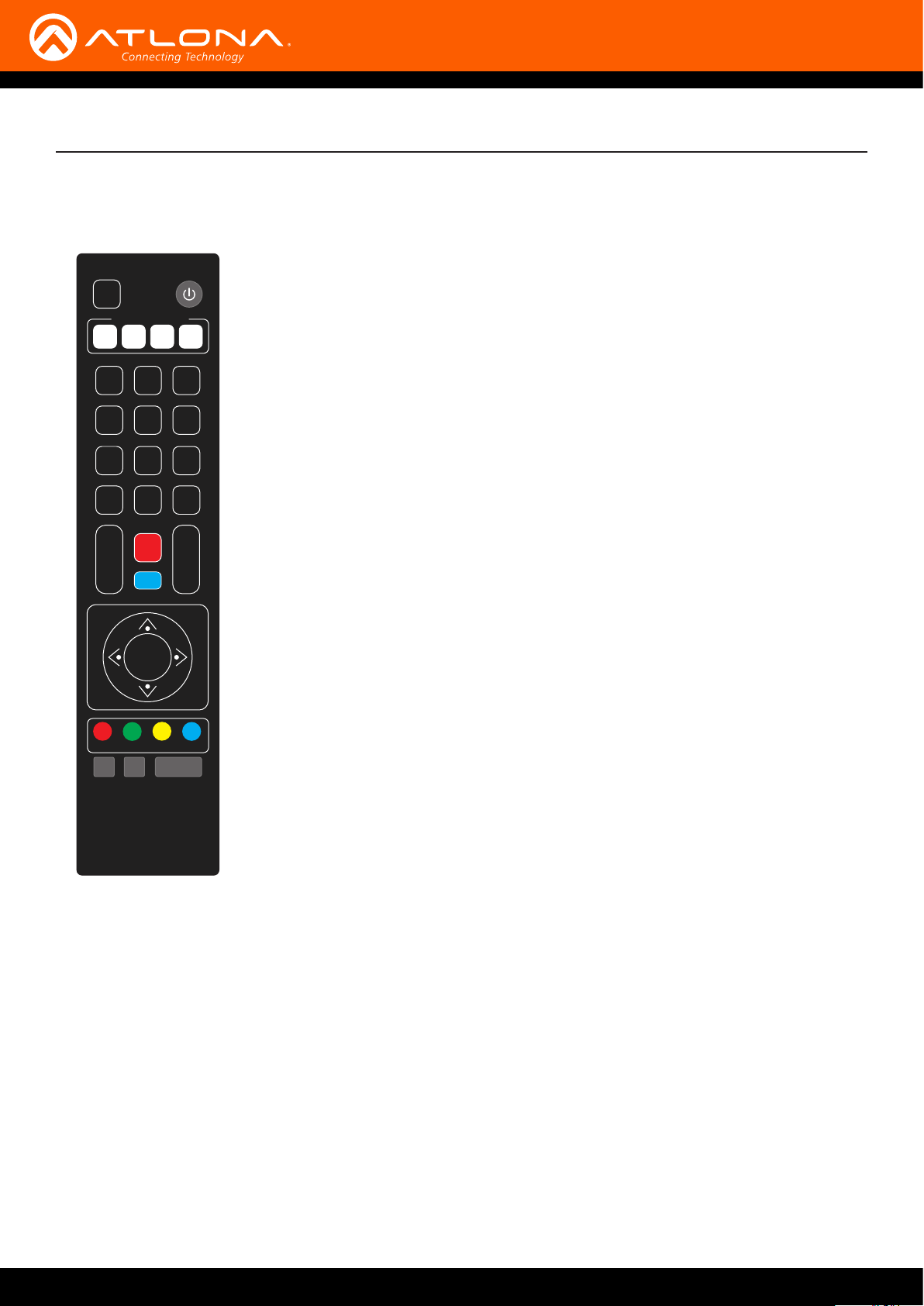
IR Remote and OSD
IR Remote Control
The AT-HDVS-CAM comes with an IR remote control for full control of the camera and use of the OSD menu.
IR Remote
SET
CAMERA SELECT
1
2 3
1 2 3
4 5 6
7 8 9
8 #
*
+
AUTO
FOCUS ZOOM
_ _
MANUAL
SET
PRESET
HOME
4
+
CLEAR
PRESET
Power - Toggle the camera on and o with the power button. Press and hold for 3
seconds to place the camera into standby mode.
Number Buttons - Use in the selection or creation of camera presets.
Focus - Adjust the focus of the camera using the + and - buttons.
Auto - Switch the camera focus mode to auto.
Manual - Switch the camera focus mode to manual.
Zoom - Zoom in (+) or out (-) using these buttons.
Set Preset - Set the camera into position then press the Set Preset button followed by
a number key (0-9) to set that position to a preset.
Clear Preset - Press clear preset followed by a number key to erase the preset set to
that number.
Arrow Buttons - Use the arrow buttons to adjust the camera position or navigate within
the OSD menu.
Home Buttons - Returns the camera to the middle position.
BLC ON/OFF - Toggle the back light on and o.
Menu - Use to pull up the OSD menu.
BLC
ON/OFF
F1 F2 F3 F4
MENU
The OSD will display after pressing the MENU button.
OSD
AT-OMNI-232
30
Page 31

AT-OMNI-232
31
Page 32

AT-OMNI-232
32
Page 33

Appendix
Specications
Video
HD/SD/VESA
(all resolutions are
@30/25/20/15/10/5Hz)
Optical Zoom 10X, f = 4.7 ~ 47 mm
Viewing Angle 6.43° (telephoto), 60.9° (wide-angle)
Eective Pixels 2.07 MP
Focus Settings Auto / Manual
AV F1.6 - F3.0
Minimum Illumination 0.5 lm, F1.8 with Automatic Gain Contol ON
Signal-to-Noise Ratio (SNR) > 55 dB
Control Protocol VISCA/Pelco-D/Pelco-P
Pan Rotation ±170°
Tilt Rotation -30° ~ ±90°
Pan Control Speed 0.1 - 180° / sec
Tilt Control Speed 0.1 - 80° / sec
1080p, 720p, 1024x768, 1024x576, 960x540, 800x600, 640x360, 720x576,
640x480, 352x288, 320x240, 320x180, 176x144
Temperature Fahrenheit Celsius
Operating 14 to 122 -10 to 50
Storage -14 to 140 -10 to 60
Operating Humidity (RH) 20% to 80%, non-condensing
Storage Humidity (RH) 20% to 95%, non-condensing
Power
Consumption 12 W
Supply Input: 110 - 220 V AC, 50/60 Hz
Output: 12 V DC, 1 A
Dimensions Inches Millimeters
H x W x D 6.59 x 5.90 x 5.90 167.5 x 150 x 150
Weight Pounds Kilograms
Device 3.08 1.4
Certication
Device CE, FCC
AT-OMNI-232
33
Page 34

Index
C
Connection
diagram 10
instructions 10
Contents
package 8
Customer support 3
F
FCC statement 6
Features 8
I
Installation 10
O
Operating notes 3
P
Panel descriptions 9
S
Safety information 6
Specications 30
W
Warranty 4
AT-OMNI-232
34
Page 35

atlona.com • 408.962.0515 • 877.536.3976
© 2017 Atlona Inc. All rights reserved. “Atlona” and the Atlona logo are registered trademarks of Atlona Inc. All other brand names and trademarks or registered trademarks are the property of their respective owners. Pricing, specications and availability
subject to change without notice. Actual products, product images, and online product images may vary from images shown here.
 Loading...