

Page 1
Installation Guide
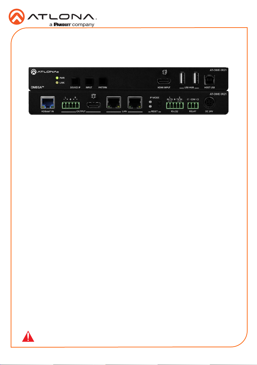
AT-OME-SR21
Omega 4K/UHD Scaler for HDBaseT and HDMI with USB
AT-OME-SR21
The Atlona AT-OME-SR21 is an HDBaseT receiver and 4K/UHD scaler with a local HDMI
input. Part of the Omega™ Series of integration products for modern AV communications and
collaboration, the OME-SR21 receives HDBaseT for video up to 4K/60 4:2:0, plus embedded
audio, control, Ethernet, and USB over distances up to 330 feet (100 meters). The HDMI input
supports video up to UHD/60 4:4:4. The OME-SR21 is HDCP 2.2 compliant and features 4K/60
upscaling and downscaling with frame rate conversion. Additionally, it receives USB over
HDBaseT and includes a USB 2.0 hub for integration with PCs, cameras, microphones, speakers,
DSPs, and touch or interactive displays. The OME-SR21 is ideal for 4K presentation applications
with Omega, HDVS-200, or UHD-EX Series transmitters, as well as Atlona AV presentation
switchers with HDBaseT outputs, local HDMI sources, and the Gain™ Series ampliers.
The OME-SR21 combines the benets of 4K/UHD scaling, auto-switching for HDBaseT and
HDMI inputs, integrated display control, USB extension, and more. It incorporates many popular
integration convenience features, while delivering excellent performance and value for 4K
presentation and video conferencing applications. The OME-SR21 can remotely power an Atlona
HDBaseT transmitter through Power over Ethernet (PoE). For additional integration convenience,
the OME-SR21 features audio de-embedding, integrated two-port Ethernet switch, contact
closure ports for controlling a motorized screen or display lift, internal video test patterns for
setup and troubleshooting, and remote management with AMS (Atlona Management System).
Package Contents
1 x AT-OME-SR21
2 x Captive screw connector, 5-pin
1 x Captive screw connector, 3-pin
4 x Mounting screws
1 x Pair rack mount ears
1 x 24V DC power supply
1 x IEC power cord
1 x Installation Guide
IMPORTANT: Visit https://atlona.com/product/AT-OME-SR21 for the latest rmware
updates and User Manual.
1
Page 2
Panel Descriptions
Installation Guide
AT-OME-SR21
1 2 3 4 5 7
PWR
LINK
TM
TM
OMEGA
L R
+
+
HDBaseT IN
OUTPUT
10
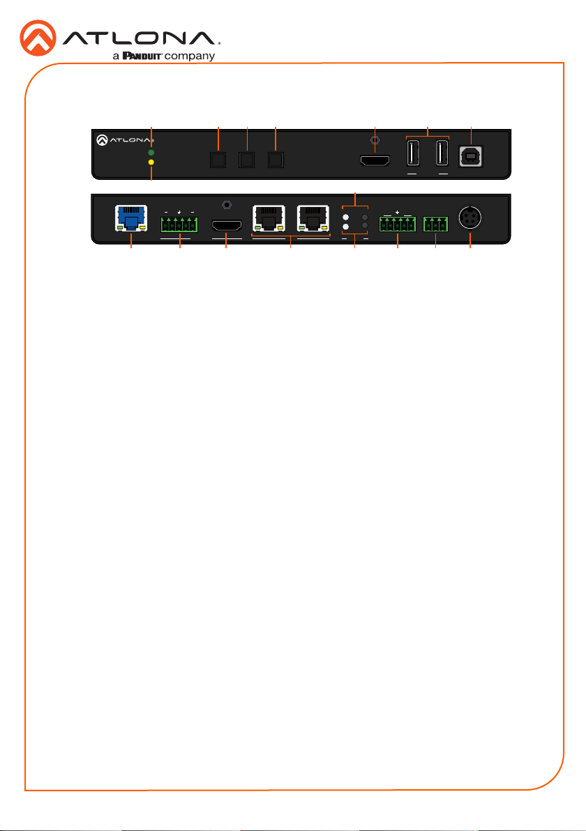
1 PWR LED
Illuminates green when receiving power.
2 DEVICE IP button
Press to display the unit IP in the top left
corner of the connected display.
3 INPUT button
Use to switch between the HDMI and
HDBaseT inputs. If the device is currently
showing a pattern for source, pressing the
input button will bring up the last selected
input.
4 PATTERN button
Use to send one of the three source
patterns built into the unit. Press to cycle
through all three patterns.
5 HDMI IN
Connect an HDMI cable from an HDMI
source to this port.
6 USB HUB
Connect USB devices to these ports. e.g.
usb camera, mouse, etc.
7 HOST USB
Connect to a computer using a USB B to
USB A cable.
8 LINK LED
Illuminates yellow when receiving signal
from the HDBaseT input port.
9 IP MODE button and LED
Press and hold the button for 5 seconds
until the LED blinks to switch the IP mode
between DHCP and Static IP modes. The
LED will blink 2 times for DHCP and 3
times for static IP.
6
AT-OME-SR21
INPUT PATTERNDEVICE IP
USB HUBOMEGA
HOST USBHDMI IN
98
IP MODE
1 2
RX RXTX TX
1
2
LAN DC 24VRELAY
1311 12 15 16 17
RESET RS-232
14
C1 COM C2
10 HDBaseT IN
Connect a compatible HDBaseT
transmitter to this port.
11 AUDIO OUT
Connect to an audio DSP, amplier, or
other audio distribution devices.
12 HDMI OUT
Connect an HDMI cable from here to an
HDMI display.
13 LAN
Connect Ethernet cables to these ports for
control of the unit and/or to pass Ethernet
to a local device.
14 RESET button and LED
Press and hold the button for 5 seconds
until the unit resets. The LED will blink as
the unit resets to factory default settings.
15 RS-232
Use for device and display control.
16 RELAY
Dual low-voltage signal relay to control
devices such as electric screens and
display lifts.
17 DC 24V
Connect the included DC 24V power
supply to this port.
AT-OME-SR21
2
Page 3
RS-232
GND RX
TX
GNDRX TX
RX TX
L R
L R
C2C1 COM
Open
Closed
Installation Guide
AT-OME-SR21
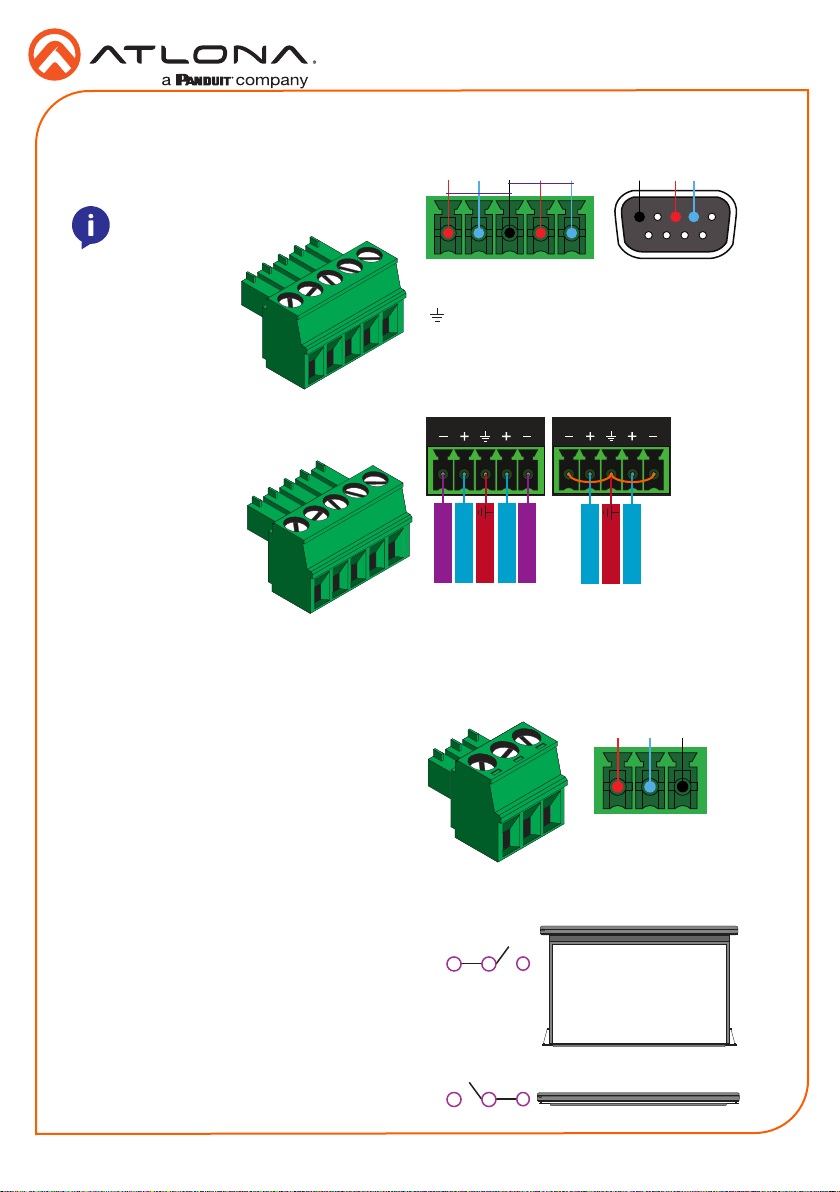
A 5-pin captive screw connector has been
included for RS-232.
NOTE: Port 1 is for display control and
port 2 will control the unit.
Audio
Connect to an audio DSP, amplier, or other
audio distribution devices.
Relay
A dual low-voltage signal relay is built into
the OME-SR21 for control of devices such
as electric screens and display lifts. A 3-pin
captive screw connector has been included
for connection.
1 2
Pin out will be determined by the RS-232 cable
and connect as RX (receive), TX (transmit) and
(Ground). Ground will be shared between
port 1 and port 2.
+
+
-
Negative
Positive
Ground
Balanced
-
Negative
Positive
+
+
Positive
Positive
Ground
Unbalanced
Use a jumper between the negative and ground
pins when using an unbalanced connection.
When using a dual signal relay with an electric
projection screen, it allows for two dierent
circuits to be controlled: up and down
(pictured to the right).
The relay will default to follow the display. When
the unit turns on the relay will close C1 and
open C2. When the display is turned o and
signal is no longer being received C1 will open
and C2 will close.
There are 3 connections for the relay: C1, COM,
and C2 (Circuit 1, Common, and Circuit 2.)
Down
C1
Closed
C1
COM
Up
COM
C2
Open
C2
3
Page 4
Installation Guide
AT-OME-SR21
Mounting Instructions
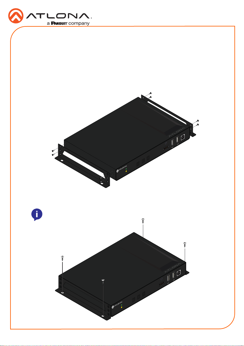
The AT-OME-SR21 includes two mounting brackets and four mounting screws, which can be
used to attach the units to any at surface.
1. Remove the top 2 case screws on the side of the unit.
2. Align the mounting brackets to the side of the units.
3. Use the previously removed case screws to secure the mounting bracket to the enclosure.
4. Repeat the steps for the other side of the unit.
AT-OME-SR21
C1 COM C2
1 2
RX RXTX TX
IP MODE
RESET RS-232
2
LAN DC 24VRELAY
HDBaseT IN
1
+
L R
+
OUTPUT
INPUT PATTERNDEVICE IP
PWR
LINK
TM
TM
OMEGA
OMEGA
USB HUB
AT-OME-SR21
HOST USBHDMI IN
5. Mount the unit using the oval-shaped holes, on each mounting bracket. If using a drywall
surface, a #6 drywall screw is recommended.
NOTE: Mounting brackets can also be inverted to mount the unit under a table
or other at surface.
AT-OME-SR21
C1 COM C2
1 2
RX RXTX TX
IP MODE
RESET RS-232
2
LAN DC 24VRELAY
HDBaseT IN
1
+
L R
+
OUTPUT
INPUT PATTERNDEVICE IP
PWR
LINK
TM
TM
OMEGA
OMEGA
USB HUB
AT-OME-SR21
HOST USBHDMI IN
4
Page 5
Installation Guide
AT-OME-SR21
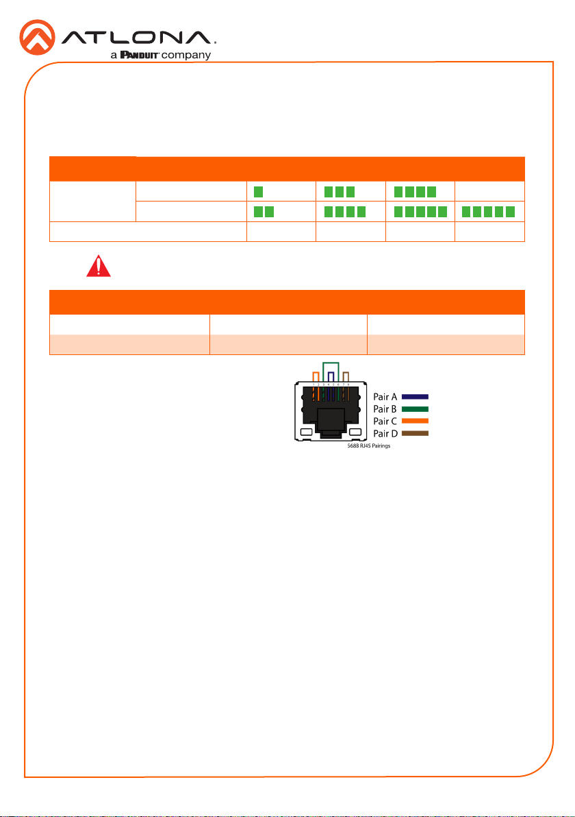
Cable Recommendation Guidelines
Refer to the tables below for recommended cabling when using Altona products with HDBaseT.
The green bars indicate the signal quality when using each type of cable. Higher-quality signals
are represented by more bars.
Core Shielding CAT5e CAT 6 CAT6a CAT7
Solid UTP (unshielded) N/A
STP (shielded)
Performance Rating (MHz) 350 500 600 800
IMPORTANT: Stranded or patch cables are not recommended due to
performance issues.
Cable Max. Distance @ 4K Max. Distance @ 1080p
CAT5e 295 feet (90 meters) 330 feet (100 meters)
CAT6 / CAT6a / CAT7 330 feet (100 meters) 330 feet (100 meters)
Use of a TIA/EIA 568B termination is
recommended for optimal performance.
Installation
1. Connect an HDMI source to the HDMI IN port.
2. Connect a compatible HDBaseT transmitter (e.g. AT-OME-ST31 or AT-OME-EX-TX) to the
HDBaseT input port using a category cable.
3. Connect an HDMI cable from the output port to an HDMI display.
4. *Optional* Connect the 2CH analog AUDIO OUT ports to a DSP, or audio amplier.
5. *Optional* Connect USB devices (e.g. USB camera) to the USB hub ports.
6. *Optional* Connect the HOST USB port to a computer using a USB B to USB A cable (cable
not provided).
7. *Optional* Connect to the 5-pin captive screw RS-232 port to control the display (port 1)
and the unit (port 2).
8. *Optional* Connect a network switch to one of the LAN ports, for IP control, system
conguration, or Ethernet routing.
9. *Optional* Connect a second Ethernet cable from the second LAN port to the local display
to pass through Ethernet.
10. *Optional* To control devices such as electric screens and display lifts, connect the device
to the 3-pin captive screw relay port.
11. Connect the included DC 24V power supply to the power port.
12. Connect the included IEC power cord from the power supply to a compatible power outlet.
5
Page 6

Installation Guide
AT-OME-SR21
IP
DHCP
By default, the AT-OME-SR21 is set to DHCP mode. In this mode, when the AT-OME-SR21 is
connected to the Local Area Network (LAN), it will automatically be assigned an IP address by
the DHCP server (if available). Press the DEVICE IP button to show the IP address in the top left
corner of the display.
Static
If no DHCP server is available, or a static IP is required, the OME-SR21 can be set to static IP
mode using the IP mode button.
• Press and hold the IP MODE button for 5 seconds to switch to static IP mode, the LED will
blink 3 times when it goes into Static IP mode. In this mode, the AT-OME-SR21 will be set
to the following:
IP address: 192.168.1.254
Subnet mask 255.255.0.0
Gateway: 192.168.1.1
• To switch back to DHCP, press and hold the IP mode button for 5 seconds. The LED will
blink 2 times when successfully put into DHCP mode.
Accessing the webGUI
The AT-OME-SR21 includes a built-in webGUI, which allows easy remote management and
control of all features. Follow the instructions below to access the webGUI.
1. Make sure that an Ethernet cable is connected between the LAN port on the AT-OME-SR21
and the network.
2. Press the DEVICE IP button on the front panel to display the IP address of the unit in the
top left corner of the connected display.
3. Launch a web browser and enter the IP address in the address bar.
4. The AT-OME-SR21 Login page will be displayed.
5. Enter the following information on the Login page.
Login: admin
Password: Atlona
6. Click the Login button.
7. Refer to the user manual for detailed operation of the webGUI.
6
Page 7

Installation Guide
AT-OME-SR21
AMS 2.0
For easy conguration of Atlona devices , AMS 2.0 is available from https://atlona.com/ams for
free. Two options can be used for installation: The free Linux based software download or the
easy to install server hardware (AT-AMS-HW).
Once AMS has been set up:
1. Open a browser on the same network as AMS 2.0 and go to the IP address of AMS 2.0.
View the AMS 2.0 installation instructions on how to nd the IP address of the software.
2. Enter the login information on the AMS 2.0 web page, then click the Login button.
3. View the AT-OME-SR21 manual for routing and conguration information.
7
Page 8

Installation Guide
AT-OME-SR21
Version 1
atlona.com • 877.536.3976 • 41.43.508.4321
Toll free US International
© 2019 Atlona Inc. All rights reserved. “Atlona” and the Atlona logo are registered trademarks of Atlona Inc. All other brand names and trademarks or registered
trademarks are the property of their respective owners. Pricing, specications and availability subject to change without notice. Actual products, product images, and
online product images may vary from images shown here.
8
 Loading...