

Page 1

PTZ Camera with HDBaseT Output
AT-HDVS-CAM-HDBT
Atlona Manuals
Accessories
Page 2

Version Information
Version Release Date Notes
5 Jan 2024 Updated warranty information
AT-HDVS-CAM-HDBT
2
Page 3
Sales, Marketing, and Customer Support
Main Oce
Atlona Incorporated
70 Daggett Drive
San Jose, CA 95134
United States
Oce: +1.408.962.0515
Sales and Customer Service Hours
Monday - Friday: 6:00 a.m. - 4:30 p.m. (PST)
https://atlona.com/
Operating Notes
IMPORTANT: Visit http://www.atlona.com/product/AT-HDVS-CAM-HDBT for the latest rmware
updates and User Manual.
International Headquarters
Atlona International AG
Tdistrasse 18
8002 Zrich
Switzerland
Oce: +41.43.508.4321
Sales and Customer Service Hours
Monday - Friday: 09:00 - 17:00 (UTC +1)
Warranty
To view the product warranty, use the following link or QR code:
https://atlona.com/warranty/.
AT-HDVS-CAM-HDBT
3
Page 4
Important Safety Information
CAUTION
RISK OF ELECTRIC SHOCK
DO NOT OPEN
CAUTION: TO REDUCT THE RISK OF
DO NOT OPEN ENCLOSURE OR EXPOSE
The exclamation point within an equilateral triangle is intended to alert the user to
the presence of important operating and maintenance instructions in the literature
accompanying the product.
The information bubble is intended to alert the user to helpful or optional operational instructions in the literature accompanying the product.
ELECTRIC SHOCK
TO RAIN OR MOISTURE.
NO USER-SERVICEABLE PARTS
INSIDE REFER SERVICING TO
QUALIFIED SERVICE PERSONNEL.
1. Read these instructions.
2. Keep these instructions.
3. Heed all warnings.
4. Follow all instructions.
5. Do not use this product near water.
6. Clean only with a dry cloth.
7. Do not block any ventilation openings. Install in
accordance with the manufacturer’s instructions.
8. Do not install or place this product near any heat
sources such as radiators, heat registers, stoves, or
other apparatus (including ampliers) that produce
heat.
9. Do not defeat the safety purpose of a polarized
or grounding-type plug. A polarized plug has two
blades with one wider than the other. A grounding
type plug has two blades and a third grounding
prong. The wide blade or the third prong are
provided for your safety. If the provided plug does
not t into your outlet, consult an electrician for
replacement of the obsolete outlet.
10. Protect the power cord from being walked on
or pinched particularly at plugs, convenience
receptacles, and the point where they exit from the
product.
11. Only use attachments/accessories specied by
Atlona.
12. To reduce the risk of electric shock and/or damage
to this product, never handle or touch this unit or
power cord if your hands are wet or damp. Do not
expose this product to rain or moisture.
13. Unplug this product during lightning storms or when
unused for long periods of time.
14. Refer all servicing to qualied service personnel.
Servicing is required when the product has been
damaged in any way, such as power-supply cord or
plug is damaged, liquid has been spilled or objects
have fallen into the product, the product has been
exposed to rain or moisture, does not operate
normally, or has been dropped.
FCC Compliance
FCC Compliance and Advisory Statement: This hardware device complies with Part 15 of the FCC rules. Operation is subject to the following two
conditions: 1) this device may not cause harmful interference, and 2) this device must accept any interference received including interference that
may cause undesired operation. This equipment has been tested and found to comply with the limits for a Class A digital device, pursuant to Part
15 of the FCC Rules. These limits are designed to provide reasonable protection against harmful interference in a commercial installation. This
equipment generates, uses, and can radiate radio frequency energy and, if not installed or used in accordance with the instructions, may cause
harmful interference to radio communications. However there is no guarantee that interference will not occur in a particular installation. If this
equipment does cause harmful interference to radio or television reception, which can be determined by turning the equipment o and on, the user
is encouraged to try to correct the interference by one or more of the following measures: 1) reorient or relocate the receiving antenna; 2) increase
the separation between the equipment and the receiver; 3) connect the equipment to an outlet on a circuit dierent from that to which the receiver
is connected; 4) consult the dealer or an experienced radio/TV technician for help. Any changes or modications not expressly approved by the
party responsible for compliance could void the user’s authority to operate the equipment. Where shielded interface cables have been provided
with the product or specied additional components or accessories elsewhere dened to be used with the installation of the product, they must be
used in order to ensure compliance with FCC regulations.
Copyright, Trademark, and Registration
© 2024 Atlona Inc. All rights reserved. “Atlona” and the Atlona logo are registered trademarks of Atlona Inc. Pricing, specications and availability
subject to change without notice. Actual products, product images, and online product images may vary from images shown here.
All other trademark(s), copyright(s), and registered technologies mentioned in this document are the properties of their respective owner(s).
AT-HDVS-CAM-HDBT
4
Page 5

Table of Contents
Introduction 7
Features 7
Package Contents 7
Panel Description 8
Installation 9
Connection Instructions 9
Mounting Instructions 9
Wall Mount Installation 9
Ceiling Mount Installation 10
Connection Diagram 11
Device Operation 12
Initialization Procedure 12
Home Position 13
Field of View 14
Sample Calculations Table 14
Calculating Specic Values 15
Controlling the Camera 16
Tilt 16
Pan (Rotation) 16
Tilt and Pan Combinations 17
Zoom 18
Focus 18
Backlight Compensation (BLC) 19
Standby Mode 19
Managing Presets 20
Saving Presets 20
Clearing a Preset 20
Recalling Presets 20
Multiple Camera Control 21
Assigning / Changing the Camera Address ID 21
Selecting a Camera for Control 21
Network Streaming 22
Video Stream Conguration 22
Audio Stream Conguration 25
RTMP Publishing 27
RTP Multicast 28
Conguration and Management Interfaces 29
Web Server 29
Registration 29
Logging In 30
Status Page 31
Firmware Page 32
System Page 33
Network Page 35
User Page 37
Encoding Page 38
Publishing Page 40
RTP Multicast Page 41
Reset Page 42
Audio Page 43
Picture Page 45
Focus Page 47
Exposure Page 48
Noise Reduction Page 50
AT-HDVS-CAM-HDBT
5
Page 6

Table of Contents
Style Page 51
OSD Page 52
Video Out Page 53
Control Page 54
IR Remote and OSD 55
IR Remote Control 55
OSD 55
Remote Functions 57
Appendix 58
Using VLC Player 58
Using Facebook Live 60
Using YouTube Live 63
Specications 68
AT-HDVS-CAM-HDBT
6
Page 7

Introduction
The Atlona AT-HDVS-CAM-HDBT is an enterprise-grade PTZ camera designed for use in video conferencing and
other applications such as lecture capture and distance learning. It features an HDBaseT output for extending video,
audio, power, and camera control over distances up to 330 feet (100 meters). The HDVS-CAM-HDBT is ideal for
remotely interfacing into HDBaseT equipped switchers and extenders, for use with a video conferencing codec,
lecture capture appliance, or PC equipped for video capture. Camera control over HDBaseT or TCP/IP facilitates
remote integration into AV control systems. The HDVS-CAM-HDBT delivers high performance, professional-
quality imaging with video resolutions up to 1080p @ 60 Hz, as well as fast and accurate auto-focusing, and a fast
yet quiet pan and tilt mechanism. Also available is H.264 or H.265 streaming over IP with support for RTMP and
RTSP protocols. This PTZ camera is ideal for large meeting spaces, classrooms, training rooms, and many other
environments. The HDVS-CAM-HDBT is available in black or white.
Features
• Designed for video conferencing and other applications such as lecture capture and distance education.
• HDBaseT output for extending video, audio, power, and camera RS-232 control up to 330 feet (100 meters) @
1080p with CAT5e/6 cable.
• Remote powering over HDBaseT – local powering available with included power supply.
• High performance imaging, ne detail, and color rendering with 1/2.8” low-noise, HD CMOS sensor.
• Delivers HD video resolutions including 1080p @ 60 Hz.
• Up to 255 camera presets available, 10 accessible from IR remote.
• Fast and accurate auto focus, plus auto white balance and auto exposure modes.
• Fast and quiet pan and tilt mechanism.
• Multi-element zoom lens with 10x optical zoom and a 60.9° horizontal eld of view.
• Picture controls available for brightness, color, saturation, contrast, sharpness, and gamma.
• TCP/IP, RS-232, and IR control – convenient handheld IR remote control included.
• Supports VISCA, Pelco-D, and Pelco-P camera control protocols.
• H.264 and H.265 video over IP network streaming available, with support for RTMP and RTSP protocols.
• Stereo 3.5 mm audio input for sending audio over the HDBaseT connection, and can be used for AAC or MP3
streaming over IP.
• Easy, GUI-based conguration using integrated web server.
• Camera can be mounted on a wall, or inverted for ceiling installation with the optional AT-HDVS-CAM-CMNT ceiling mount kit.
• Includes installation guide, wall mounting bracket, IR remote control, VISCA to RS-232 DB-9 adapter, lens cap,
and external universal power supply.
• Available in black or white.
Package Contents
1 x AT-HDVS-CAM-HDBT-BK or AT-HDVS-CAM-HDBT-WH
1 x Wall mounting plate
1 x 1/4 20OUNC screws
1 x IR Remote Control
1 x VISCA to RS-232 DB-9 adapter
2 x AAA battery
1 x 12 V DC power supply
1 x Installation Guide
AT-HDVS-CAM-HDBT
7
Page 8

Panel Description
Front (AT-HDVS-CAM-HDBT-WH shown) Back (AT-HDVS-CAM-HDBT-BK shown)
.
3
0
F
-
6
.
1
F
m
o
o
Z
X
0
1
m
m
7
4
f
-
m
m
7
.
4
f
6
-
F
0
3
.
f
4
.
7
m
m
-
f
4
7
m
m
1
0
X
Z
o
o
m
F
1
.
1. RS-232
Connect included VISCA to RS-232 adapter here
to control the camera with a third party software or
hardware controller.
2. AUDIO IN
Connect a 3.5 mm audio cable from an audio source,
to this port, to embed audio with video on HDBaseT
or when network streaming.
3. HDBaseT OUT
Connect to a compatible PoE switcher or receiver,
such as: AT-OME-RX11, AT-OME-PS62, etc.
RS-232 AUDIO
IN
LANHDBaseT OUT
DC 12V
AT-HDVS-CAM-HDBT-BK
1 32 4 5
4. LAN
Connect to a network switch to control the unit via
TCP/IP or web server.
5. DC 12V
Connect the included 12V power supply to this port.
AT-HDVS-CAM-HDBT
8
Page 9
Installation
RXD
RI
RTS
1
0
X
Z
o
o
m
F
1
.
6
-
F
3
.
0
f
4
.
7
m
m
-
f
4
7
m
m
1
0
X
Z
o
o
m
F
1
.
6
-
F
3
.
0
-
f
4
7
m
m
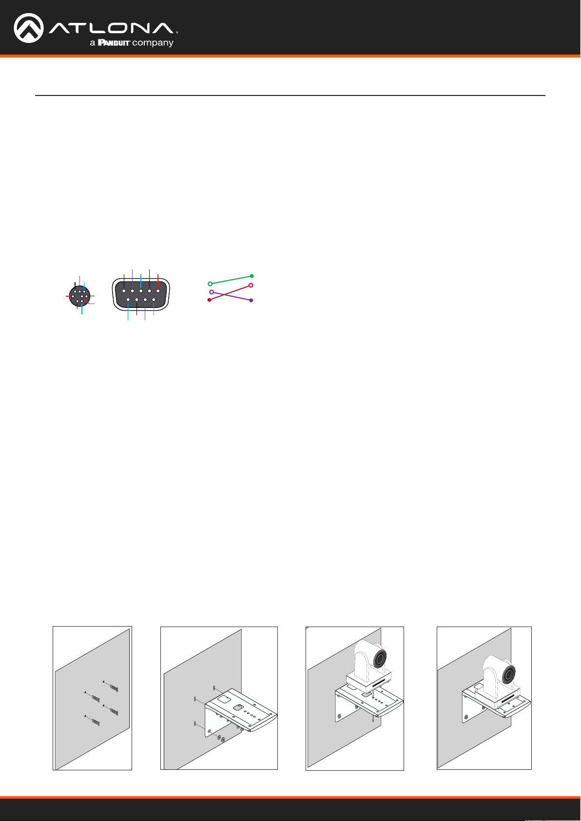
Connection Instructions
1. Connect the Ethernet cable to the LAN port on the back of the AT-HDVS-CAM-HDBT.
2. Connect to a category cable (CAT-5e or better) from the HDBaseT port to a compatible PoE A/V switcher or
receiver, such as the AT-OME-RX11.
3. *Optional* Connect the Visca to RS-232 cable to the Visca port for RS-232 control. Note that RS-232 can also
be connected to an AT-OME-RX11 or other receiver that supports RS-232 for remote control.
RXD
Visca
IR OUT
NC
DSR
DTR
GND
TXD
GND
RS-232
DSR
TXD
GND
CTS
DCD
DSR
Visca
DTR
DSR
TXD
GND
RXD
GND
IR OUT
NC
RS-232
DCD
RXD
TXD
DTR
GND
DSR
RTS
CTS
RI
4. *Optional* Connect the DC 12V power cable to the unit. This is only required if the camera is not being powered
using PoE.
Mounting Instructions
The AT-HDVS-CAM-HDBT has two installation options, wall mount (included) and ceiling mount (purchased
separately).
Wall Mount Installation
Install the AT-HDVS-CAM-HDBT, 4 M6 swelling bolts, 1 1/4 20 UNC bolt, 4 M6 nuts and shims, the included wall
mount bracket, and the AT-HDVS-CAM-HDBT are needed.
1. Install the M6 swelling bolts in a rectangular pattern on the wall, 100 mm wide and 50 mm high.
2. Attached the wall mount bracket onto the wall, by placing them on the M6 swelling bolts and securing it with the
M6 nuts and shims.
3. Once the wall mount bracket is secure on the wall, place the camera on the top of the wall mount bracket and
secure it with the 1/4 20UNC bolt.
f
4
.
0
7
.
3
m
F
m
-
6
-
.
f
1
F
4
7
m
m
m
o
o
Z
X
0
1
m
m
1
7
0
X
4
f
Z
o
-
o
0
m
.
3
F
F
-
1
.
AT-HDVS-CAM-HDBT
6
f
4
.
0
7
.
3
m
F
m
-
6
-
.
f
1
F
4
7
m
m
m
o
o
Z
X
0
1
m
m
1
7
0
X
4
f
Z
o
-
o
0
m
.
3
F
F
-
1
.
6
9
Page 10

Installation
Ceiling Mount Installation
To install the AT-HDVS-CAM-HDBT, 4 PA3X30 self-tapping screws, 4 PM3X6 screws, 4 screw stoppers, 1 1/4 20
UNC screw, the optional ceiling upper and lower covering plates, and the AT-HDVS-CAM-HDBT are needed.
1. Install the 4 screw stoppers in the ceiling.
2. Connect the upper ceiling covering plate to the screw stoppers using the PA3X30 self-tapping screws.
3. Connect the lower ceiling covering plate to the bottom of the AT-HDVS-CAM-HDBT using the 1/4 20 UNC screw.
4. Mount the lower ceiling covering plate to the upper ceiling plate using 3 PM3X6 bolts.
1 2
ON KE
1 2
ON KE
NOTE: The camera picture will need to be inverted for video to be viewed correctly. View the AT-HDVSCAM-HDBT manual for instructions on how to invert video.
AT-HDVS-CAM-HDBT
10
Page 11
AT-HDVS-CAM-HDBT
Laptop
m
m
7
m
o
o
Z
X
0
1
4
f
-
0
.
3
F
0
.
3
F
-
6
.
1
F
o
m
F
-
1
.
6
f
4
.
7
m
m
-
f
4
7
m
m
1
0
X
Z
o
Ceiling
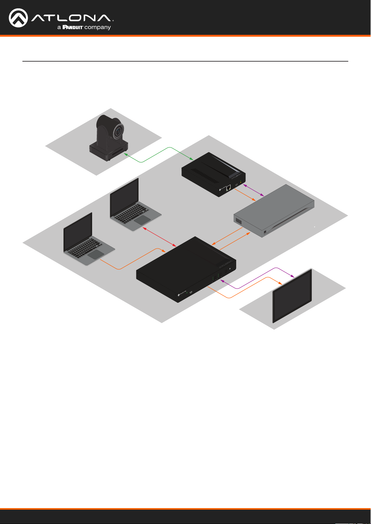
Connection Diagram
HDBaseT
Laptop
HDMI
USB-C
AT-OME-SW32
DC 24V
RXTX
RXTX
R
+
+
L R
L
+
+
RS-232 LAN
RS-232
AUDIO OUT
AUDIO OUT
OUTPUT
3 1 2
2
1
INPUT
IP MODE
RESET
PWR
FW
TM
OMEGA
AT-OME-SW32
AT-OME-RX11
1
2
3
1
OUTPUT 2 SWITCHING MODE
2
3
OUTPUT 1
LAN
HDMI
AT-OME-RX11
PWR
LINK
FW
HDMI
Video Conferencing Codec
HDMI
AT-OME-SW32
HDMI
Control
Control
Table
Installation
Codec
I
0
Wall
Display
AT-HDVS-CAM-HDBT
11
Page 12

Device Operation
IN
RS-232
OUT
USB
LAN
DC 12V
USB
AT-HDVS-CAM
IN
RS-232
OUT
USB
LAN
DC 12V
USB
AT-HDVS-CAM
Initialization Procedure
Once the camera is powered, it will go through an initialization procedure. During this process, a ashing red LED
indicator will be displayed. When the AT-HDVS-CAM-HDBT is ready for use, the LED indicator on the front panel will
be solid green. The AT-HDVS-CAM-HDBT will repeat this process each time it is powered on.
.
3
0
F
-
6
.
f
1
4
F
m
o
o
Z
X
0
1
m
m
7
4
f
-
m
m
7
.
.
7
m
m
-
f
4
7
m
m
1
0
X
Z
o
o
m
F
4
1
f
.
6
-
F
0
3
.
Flashing red LED during initialization
.
3
0
F
-
6
.
f
1
4
F
m
o
o
Z
X
0
1
m
m
7
4
f
-
m
m
7
.
7
m
m
-
f
4
7
m
m
1
0
X
Z
o
o
m
.
F
4
1
f
.
6
-
F
0
3
.
Camera “ready” state
AT-HDVS-CAM-HDBT
12
Page 13
IN
RS-232
OUT
USB
LAN
DC 12V
USB
AT-HDVS-CAM
Device Operation
Home Position
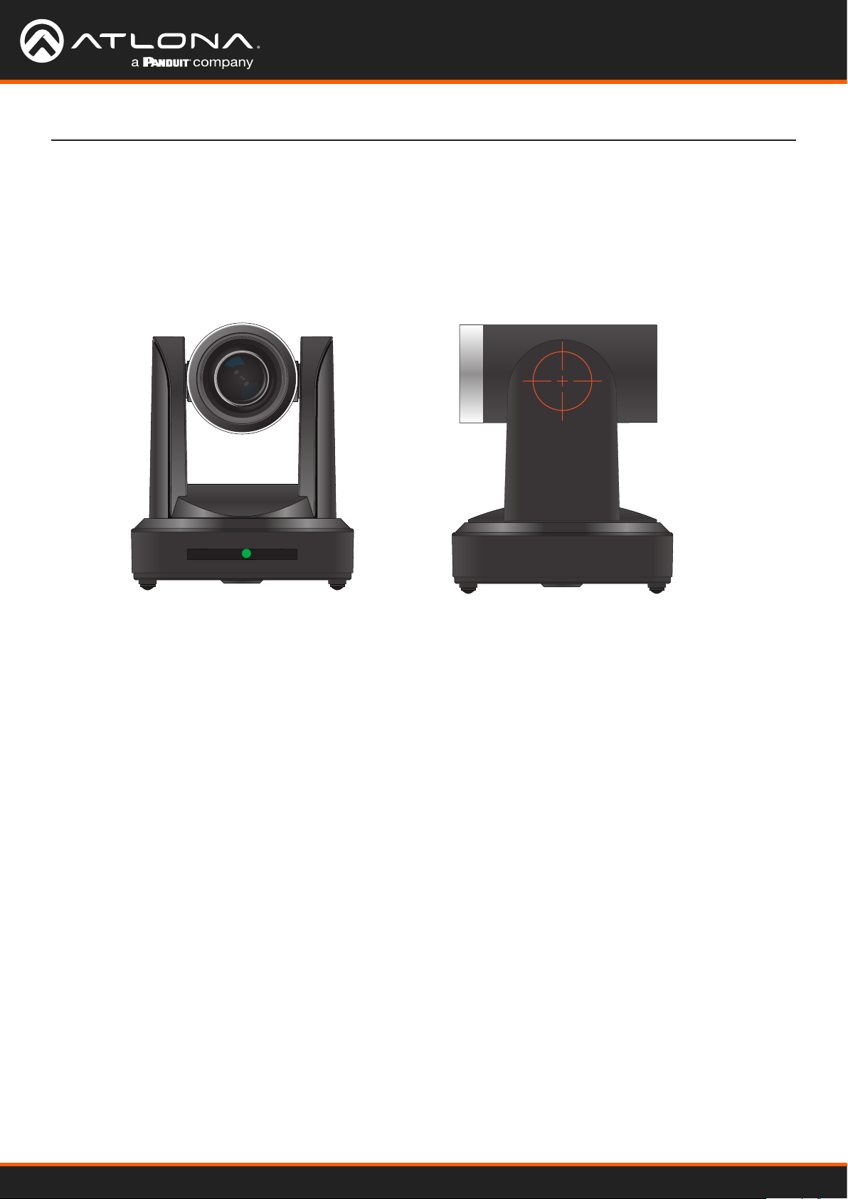
“Home” position is a term that is used throughout this manual. When the AT-HDVS-CAM-HDBT is in home position,
the camera is facing forward and has no tilt angle, as shown in the illustration below:
.
3
0
F
-
6
.
f
1
4
F
m
o
o
Z
X
0
1
m
m
7
4
f
-
m
m
7
.
7
m
m
-
f
4
7
m
m
1
0
X
Z
o
o
m
.
F
4
1
f
.
6
-
F
0
3
.
Front Left Side
AT-HDVS-CAM-HDBT
13
Page 14

Device Operation
Field of View
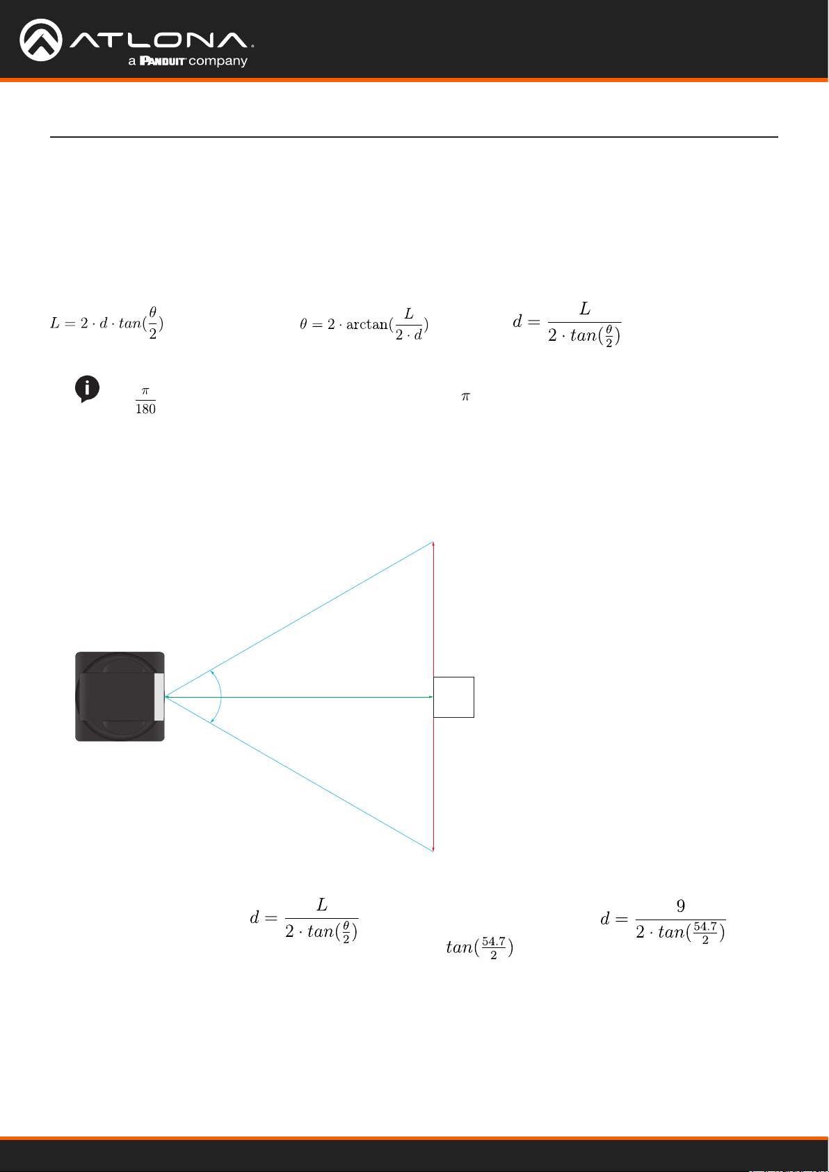
When positioning the camera in a huddle room or similar area, it will be helpful to know the viewing area of the
camera, based on a xed target. The viewable area of the camera is called the linear eld of view or sometimes
referred to as the image plane.
The illustration below shows the AT-HDVS-CAM-HDBT pointed at a xed target.
Linear Field of View (L)
Distance (d)
Angle of View (θ)
AT-HDVS-CAM
Target
Sample Calculations Table
The following table provides a list of predened distances, which the camera must be placed from the target, in order
to capture the required Linear Field of View (L). The Angle of View, for the camera, has been set to 60.9° (wideangle).
To calculate custom values, refer to Calculating Specic Values (page 15).
Angle of View (q), in degrees Distance (d), in feet Linear Field of View (L), in feet
60.9° 5 5.875076864
10 11.75015373
15 17.62523059
20 23.50030746
25 29.37538432
AT-HDVS-CAM-HDBT
14
Page 15
Device Operation
Calculating Specic Values
In order to calculate custom values, this section introduces some trigonometric formulas which can be used to nd
the Linear Field of View (L), Distance (d), or the Angle of View (q). The derivation of each formula is beyond the scope
of this manual. As long as any two values are known, the third value can be calculated as follows:
Linear Field of View (FOV) Angle of View Distance to target
NOTE: When calculating the Angle of View, using a calculator that is set to radians, multiply the result
by to convert the answer to degrees. The value of can be approximated as 3.1415.
Example
In the following diagram, the camera angle of view is set to 54.7°. The viewing area to be captured is measured to be
9 feet. How far from the target must the camera be placed in order to capture this area?
Distance = ?
Angle of View = 54.7°
AT-HDVS-CAM-HDBT
1. Use the following formula:
2. Substitute the known values for each variable in the
equation. In this case, we know both the linear FOV
and the angle of view. Therefore:
L = 9
q = 54.7
Linear FOV = 9.0 feet
Target
3. The equation becomes:
4. = 0.5172
5. Multiplying this result by 2 gives: 1.0344
6. Dividing 9 by 1.0344, yields: 8.700. Therefore, the
camera must be placed 8.7 feet from the target.
AT-HDVS-CAM-HDBT
15
Page 16

Device Operation
SET
1
AUTO
MANUAL
FOCUS ZOOM
2 3
1 2 3
4 5 6
7 8 9
*
8 #
+
_ _
+
4
CAMERA SELECT
SET
1
AUTO
MANUAL
FOCUS ZOOM
2 3
1 2 3
4 5 6
7 8 9
*
8 #
+
_ _
+
4
CAMERA SELECT
Controlling the Camera
The AT-HDVS-CAM-HDBT can be controlled using the included IR remote control, RS-232, TCP/IP, or through the
web server. Refer to the Web Server (page 29) for more information about accessing the web server.
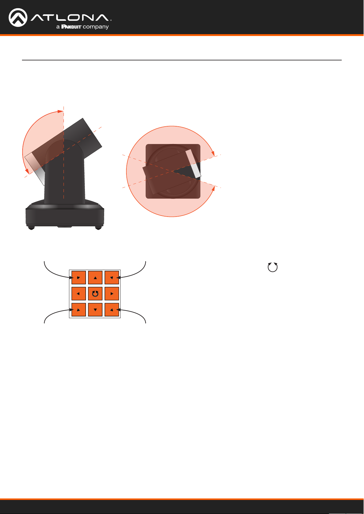
Tilt
The camera tilt range is approximately -45 degrees to +90 degrees. Use one of the following methods to adjust the
camera tilt.
IR Remote Control
• Press and release the up or down
web server
1. Click Control in the side menu bar.
arrow button to adjust the tilt of the
camera in small increments.
2. Click the up-arrow or down-arrow
button to tilt the camera up or
• Press and hold the up or down
down, respectively.
arrow button to adjust the camera
tilt at a faster rate.
3. Click the icon in the center to
return the camera to the “home”
• Press the HOME button to return
position.
the camera to the “home” position.
Tilt up
SET
PRESET
BLC
ON/OFF
HOME
CLEAR
PRESET
MENU
Tilt down
Tilt up
Tilt down
Pan (Rotation)
The camera pan range is approximately 360 degrees. Use one of the following methods to adjust the camera pan.
Front
AT-HDVS-CAM-HDBT
IR Remote Control
• Press and release the left or right
arrow button to adjust the camera
tilt in small increments.
• Press and hold the left-arrow or
right-arrow button to adjust the
camera tilt at a faster rate.
• Press the HOME button to return
the camera to the “home” position.
Pan left
SET
PRESET
BLC
ON/OFF
HOME
CLEAR
PRESET
MENU
Pan right
Pan left
web server
1. Click Control in the side menu bar.
2. Click the left arrow or right arrow
button to tilt the camera up or
down, respectively.
3. Click the icon in the center to
return the camera to the “home”
position.
Pan right
16
Page 17
Device Operation
Tilt and Pan Combinations
The web server provides a method for combining both tilt and pan motion. Note that this function is not available on
the included IR Remote Control.
web server (only)
1. Click Control in the side menu bar.
2. Click the diagonal arrow buttons
to simultaneously tilt and pan the
camera in the desired direction:
• Upper Diagonal-left arrow
Pans and rotates camera up and
Front
to the left.
• Lower Diagonal-left arrow
Pans and rotates camera down
and to the left.
• Upper Diagonal-right arrow
Pans and rotates camera up and
to the right.
Left:
Pan + tilt up
Left:
Pan + tilt down
Right:
Pan + tilt up
Right:
Pan + tilt down
• Lower Diagonal-right arrow
Pans and rotates camera down
and to the right.
3. Click the icon in the center to
return the camera to the “home”
position.
AT-HDVS-CAM-HDBT
17
Page 18

SET
1
2 3
1 2 3
4 5 6
7 8 9
*
8 #
4
CAMERA SELECT
SET
1
2 3
1 2 3
4 5 6
7 8 9
*
8 #
4
CAMERA SELECT
Device Operation
Zoom
The camera is provides a zoom factor up to 10x. Use one of the following methods to adjust the camera zoom.
IR Remote Control
• Locate the ZOOM rocker switch on the IR Remote
Control.
web server
1. Click Control in the side menu bar.
2. Click + to zoom-in or click - to zoom out.
• Press and release + to zoom-in or press - to zoom-
out.
• Press and hold the these buttons to zoom-in or
zoom-out at a faster rate.
Zoom outZoom in
Zoom in
+
FOCUS ZOOM
_ _
MANUAL
AUTO
+
Zoom out
Focus
When positioning the camera on an object, it may be necessary to adjust the focus for a clear image. The AT-HDVSCAM-HDBT can be set to auto focus or manual focus. By default, the AT-HDVS-CAM-HDBT is set to auto-focus
mode.
NOTE: In order to manually control the focus, the AT-HDVS-CAM-HDBT must be in manual focus
mode. Press the MANUAL button to enter manual focus mode.
IR Remote Control
• Press and release the MANUAL button.
• Locate the FOCUS rocker switch on the IR Remote
Control.
• Press and release + to increase focus on objects in
the foreground. Press and release the - to focus on
objects in the background.
• Press and hold the these buttons to adjust the focus
at a faster rate.
Foreground objects
Background objects
+
FOCUS ZOOM
_ _
MANUAL
AUTO
+
Manual button
web server
1. Click Control in the side menu bar.
2. Set the AT-HDVS-CAM-HDBT to manual focus mode
by selecting Manual from the Focus Mode dropdown list.
3. Click + to focus on foreground objects or click - to
focus on background objects.
Background objectsForeground objects
AT-HDVS-CAM-HDBT
18
Page 19
Device Operation
SET
1
AUTO
MANUAL
FOCUS ZOOM
2 3
1 2 3
4 5 6
7 8 9
*
8 #
+
_ _
+
4
CAMERA SELECT
1 2 3
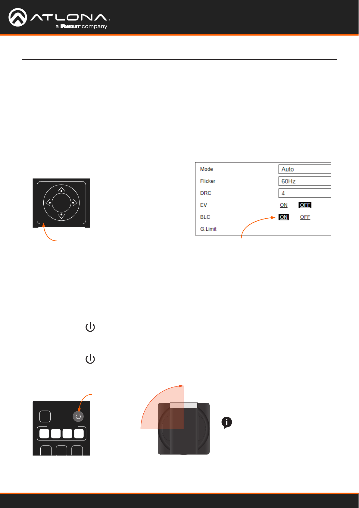
Backlight Compensation (BLC)
BLC is a feature which automatically adjusts the exposure control of the camera. When enabled, BLC will attempt to
increase the ambient foreground light and “darken” any background light. For example, a subject standing in front
of a window in the daytime, will produce a sillhouetted eect. Enabling BLC will compensate for the dierence in
lighting.
IR Remote Control
1. Point the IR Remote Control at the front of the AT-
HDVS-CAM-HDBT.
web server
1. Click Exposure in the side menu bar.
2. Click ON to enable BLC. Click OFF to disable BLC.
2. Press and release the BLC ON/OFF button to toggle
BLC on or o.
SET
PRESET
BLC
ON/OFF
HOME
CLEAR
PRESET
MENU
BLC on/off button
BLC ON
Standby Mode
Placing the AT-HDVS-CAM-HDBT in standby mode will power-down the camera. Placing the camera in standby
mode is managed using the IR Remote Control.
1. Point the IR Remote Control at the front of the AT-HDVS-CAM-HDBT.
2. Press and hold the button for three seconds.
3. The camera will rotate 90 degrees and the camera lens assembly will tilt approximately 45 degrees. The camera
is now in standby mode.
4. Press and hold the button for three seconds to wake the camera. After the camera is awake, it will return to
the home position.
Power button
NOTE: The camera will always be
set to the home position after this
SET
1
CAMERA SELECT
2 3
4
Front
sequence is performed. To return
the camera to the last position,
either position it manually or recall
the saved preset.
AT-HDVS-CAM-HDBT
19
Page 20

Device Operation
SET
1
2 3
4
CAMERA SELECT
Managing Presets
Camera positions can be stored to local memory and recalled at a later time. Presets are stored and recalled using
the included IR Remote Control. Up to 10 presets can be saved.
Saving Presets
1. Set the camera in the desired position.
2. Point the IR Remote Control at the front of the AT-HDVS-CAM-HDBT.
3. Press the SET PRESET button.
4. Press the desired number on the IR Remote Control keypad to assign the position of the camera to the preset.
1 2 3
4 5 6
7 8 9
8 #
Keypad
*
+
FOCUS ZOOM
_ _
MANUAL
SET
PRESET
HOME
BLC
ON/OFF
Clearing a Preset
Presets can be erased. It is not necessary to clear a preset, before saving a new camera position in the same preset.
If a preset is saved to an existing preset, it will be overwritten.
1. Press the CLEAR PRESET button.
2. Press the desired number on the IR Remote Control keypad to clear the preset.
NOTE: To clear all presets, press and release the [#] key on the keypad, three times.
AUTO
+
CLEAR
PRESET
MENU
Clear Preset button
Set Preset button
Recalling Presets
1. Point the IR Remote Control at the front of the AT-HDVS-CAM-HDBT.
2. Press the number of the desired preset from the IR Remote Control keypad.
3. The camera will be set to the position dened by the preset.
AT-HDVS-CAM-HDBT
20
Page 21

SET
1
2 3
1 2 3
4 5 6
7 8 9
4
CAMERA SELECT
Device Operation
Multiple Camera Control
There may be environments where more than one camera is being used. The included IR remote control unit
provides a way to select and control up to four separate cameras.
Assigning / Changing the Camera Address ID
Before the IR remote control unit can be used to control dierent camera, each camera must be assigned an address
ID. It is possible to assign multiple cameras with the same ID. However, if all cameras are within close vicinity, IR
remote control commands will be distributed to all cameras. This may not always be desirable.
1. Point the IR remote control at the front of the AT-HDVS-CAM-HDBT.
2. Assign the camera an ID by sequentially pressing the following series of buttons listed in the table below.
Camera Address ID Keystrokes
1 [*] + [#] + [F1]
2 [*] + [#] + [F2]
3 [*] + [#] + [F3]
4 [*] + [#] + [F4]
3. Follow the above steps for each camera. Each camera can
have a distinct ID. For cameras that have been assigned
unique ID addresses, it may be helpful to place a label on
each camera for future reference.
Selecting a Camera for Control
1. Point the IR remote control at the front of the desired AT-
HDVS-CAM-HDBT.
2. Press the button of the camera ID, which is being controlled,
within the CAMERA SELECT button group on the IR remote
control.
3. Press the buttons on the IR remote control for the desired
operation of the camera.
8 #
*
+
AUTO
FOCUS ZOOM
_ _
MANUAL
SET
PRESET
HOME
BLC
ON/OFF
F1 F2 F3 F4
SET
CAMERA SELECT
1
2 3
1 2 3
4 5 6
+
CLEAR
PRESET
MENU
4
# button
* button
Function buttons
Camera Select
AT-HDVS-CAM-HDBT
7 8 9
21
Page 22

Device Operation
Network Streaming
This section covers video and audio stream conguration, as well as RTMP publishing and RTP multicast. Refer to
the Appendix (page 58) on how to congure streaming using VLC, Facebook Live, and YouTube Live.
Video Stream Conguration
1. Login to the web server.
2. Click Encoding in the side menu bar.
3. Under the Video Encoding section, select the encoding protocol by clicking Enabled, next to RTSP (Real Time
Streaming Protocol) and RTMP (Real Time Messaging Protocol). Either or both protocols can be set to Enabled.
When enabled, the checkbox will contain a check mark.
Video Encoding
4. Under the Main Stream and Sub Stream sections, click each of the drop-down lists to assign the desired
settings. Both Main Stream and Sub Stream are used to view the camera’s footage.
Main Stream is the primary video feed and provides the highest quality video. Main Stream provides the highest
video quality, and is the stream used by a digital recorder when saving footage to hard disk. Adjusting these
settings will aect the recording size and available recording time on the hard disk.
Sub Stream is the secondary video feed and provides a lower quality video stream. This stream is used to
stream video to computers and mobile devices. Adjusting these settings will aect the bandwidth of the stream.
Compressed Format
The desired encoding format
Format Description
H.264 (AVC) Advanced Video Codec - Industry-standard codec that provides
good-quality compressed video output.
H.265 (HVEC) High-Eciency Video Coding - Provides a higher compression ratio
than H.264, thus reducing the bandwidth necessary for high-resolution
(2K/4K) video capture.
AT-HDVS-CAM-HDBT
22
Page 23
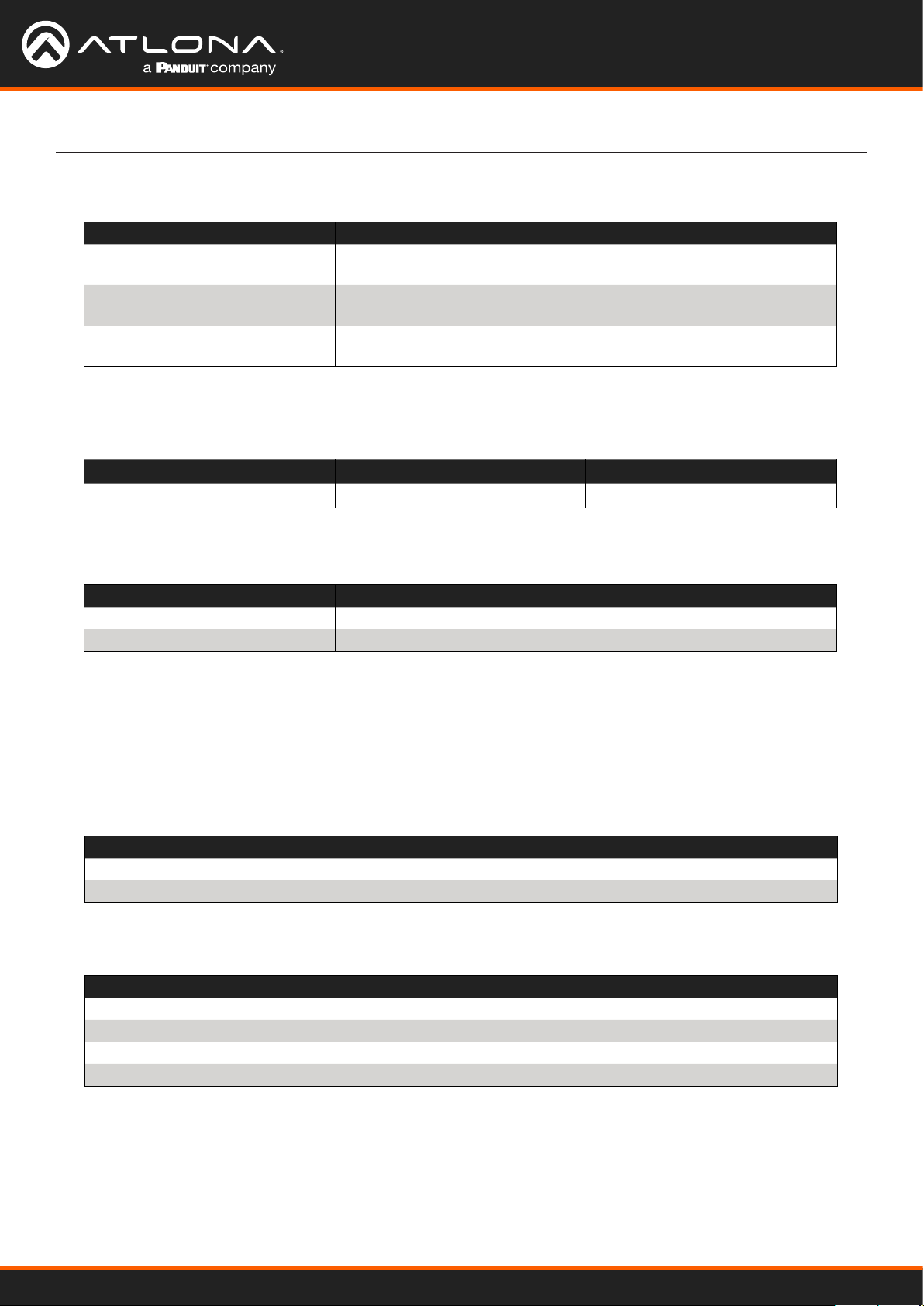
Device Operation
Prole
These options are only available when H.264 is selected. Proles are a set of encoding processes for H.264.
Prole Description
BP Baseline Prole - Supports a limited set of processes and is designed
to meet the needs of mobile devices.
MP Main Prole - Supports a good number of processes and is typically
used for devices such as set-top boxes.
HP High Prole - Supports all processes of H.264 and targets FullHD
(1080p) applications such as Blu-ray and satellite streams.
Image Size
These resolutions are available for all codecs and proles.
Resolution
1920x1080 1280x720 640x480
Bit Rate (kb/s)
Enter the desired bit rate in this eld.
Encoding Protocol Bit Rate Range
H.264 64 ... 20480 kb/s
H.265 64 ... 40960 kb/s
Stream Key
Enter the stream key in this eld. This key (code) is used to identify the stream, allowing the stream to be
displayed on a web site.
Main Stream - Recommended Settings for H.264
Resolution Bit Rate
1920x1080 4096 kb/s
1280x720 2048 kb/s
Sub Stream - Recommended Settings for H.264
Resolution Bit Rate
640x480 1024 kb/s
640x360 1024 kb/s
320x240 512 kb/s
320x180 512 kb/s
AT-HDVS-CAM-HDBT
23
Page 24
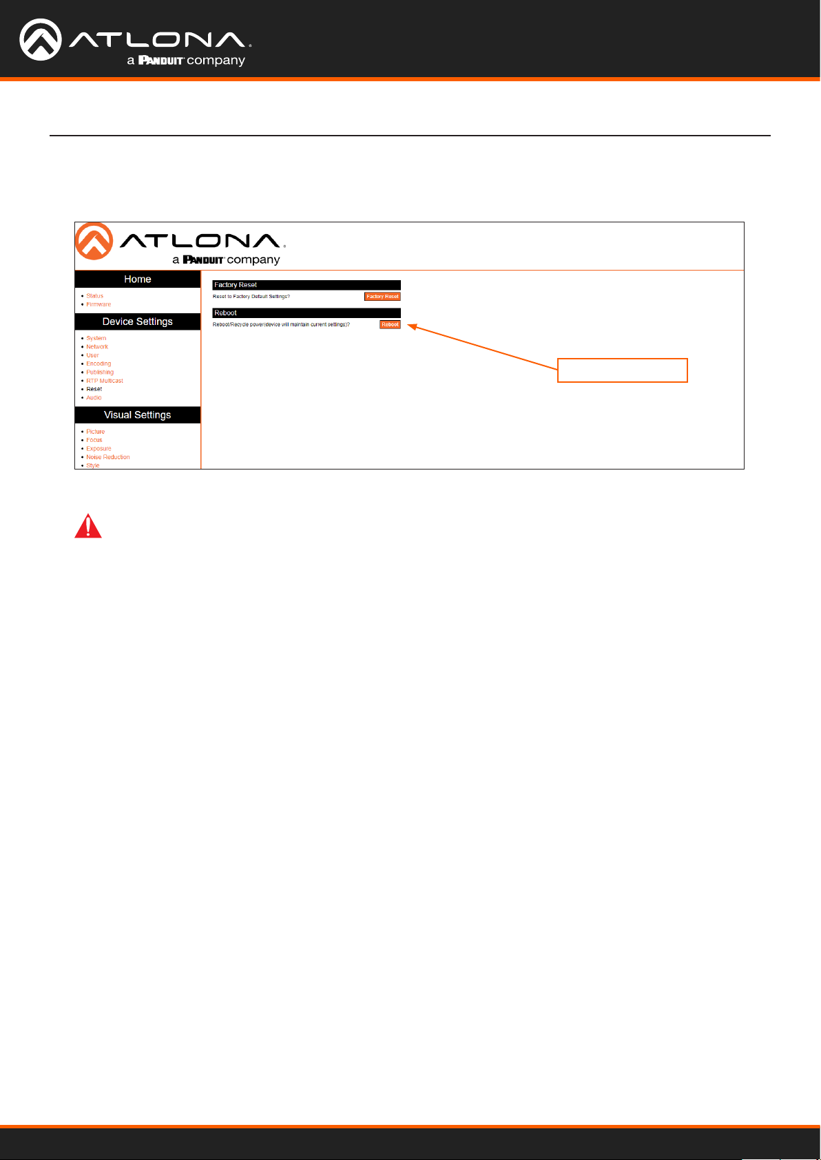
5. Click the Save button to commit changes.
6. Click Reset in the side menu bar and click the Reboot button.
IMPORTANT: After settings have been updated, streams should be re-pulled and restarted to
ensure best video quality. If the camera has been power-cycled, then it will be necessary to re-pull
both RTMP and RTSP streams.
Device Operation
Reboot button
AT-HDVS-CAM-HDBT
24
Page 25
Device Operation
Audio Stream Conguration
NOTE: Audio is embedded over the HDBaseT link.
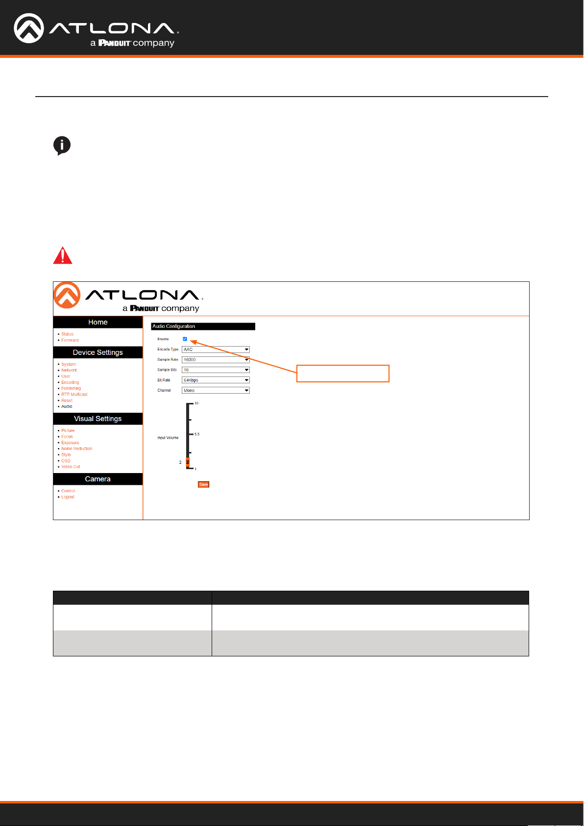
1. Login to the web server.
2. Click Audio in the side menu bar.
3. Under the Audio Conguration section, click the Enable checkbox. When enabled, the checkbox will contain a
check mark.
IMPORTANT: After enabling or disabling the Enable checkbox, the AT-HDVS-CAM-HDBT must be
rebooted in order for changes to take eect.
Enable checkbox
4. Click each of the drop-down lists to assign the desired settings.
Encode Type
Species the audio encoding type.
Encoding Bit Rate Range
AAC Advanced Audio Encoding - Industry-standard lossy compression for
digital audio. Exhibits a higher sound quality than MP3.
MP3 MPEG-1/MPEG-2 Audio Layer III - Uses lossy data-compression, dis-
carding some data, resulting in lower-bandwidth, high-quality audio.
Sample Rate
Selects the sample rate in Hertz. Available options are 16000 (16 kHz), 32000 (32 kHz), 44100, (44.1 kHz) and
48000 (48 kHz).
Sample Bits
This option is set to 16 and cannot be changed.
Bit Rate
Selects the bit rate. Available options are 32 kbps, 48 kbps, 64 kbps, 96 kbps, and 128 kbps.
AT-HDVS-CAM-HDBT
25
Page 26
Channel
Selects the number of channels that are heard on the output.
Encoding Bit Rate Range
Mono Single-channel audio stream.
Stereo Two-channel (L/R) audio stream.
Input Volume
Click and drag this slider to adjust the input volume.
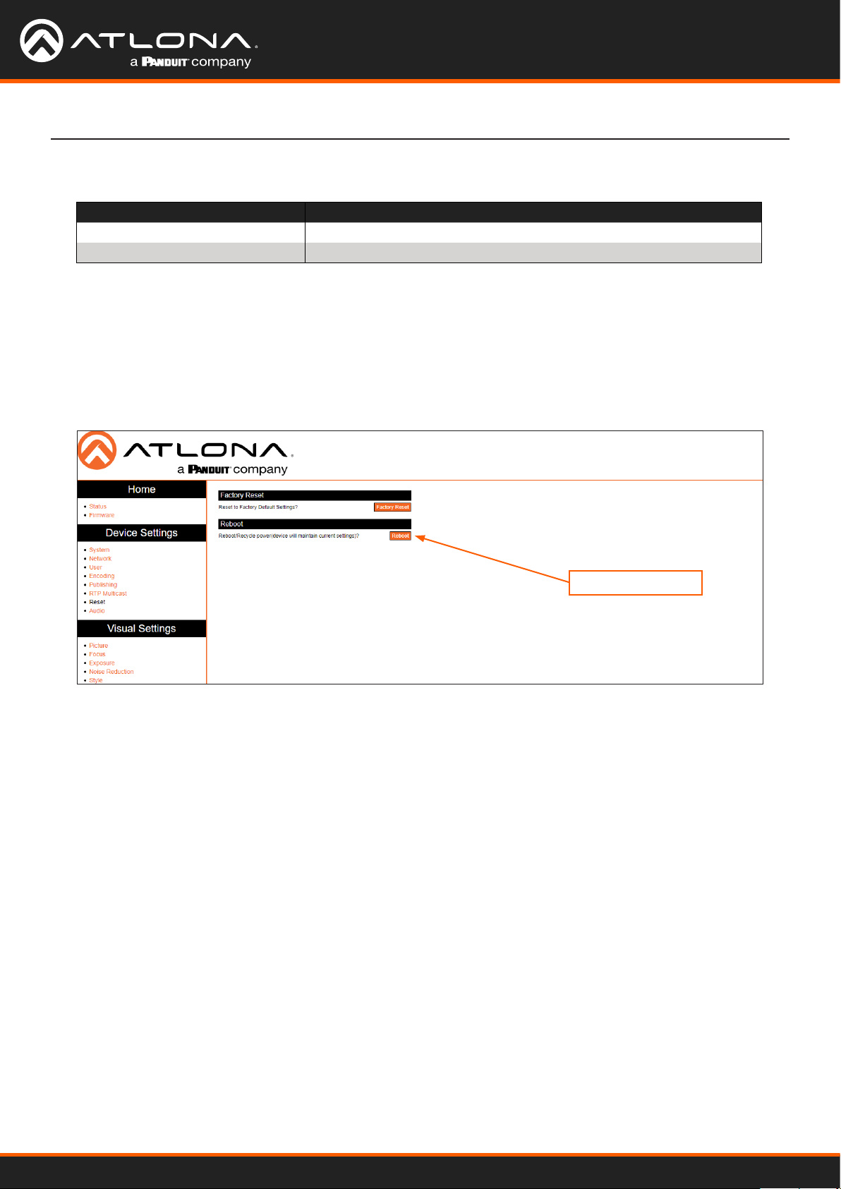
5. Click the Save button.
6. Click Reset in the side menu bar and click the Reboot button.
Device Operation
Reboot button
AT-HDVS-CAM-HDBT
26
Page 27

Device Operation
RTMP Publishing
In order to for the stream to be pushed to live-streaming platforms, such as YouTube™, Twitch®, and others, follow the
procedure below.
1. Login to the web server.
2. Click Publishing in the side menu bar. RTMP Server, under the Encoding menu, should already be enabled.
If not, refer to Video Stream Conguration (page 22) for more information.
3. Click the Enable checkbox to enable the Main Stream and/or Sub Stream.
4. Enter the host address in the Host Address eld.
5. Enter the host port in the Host Port eld.
6. Enter the stream key in the Stream Key eld. See inset image, above, for an example.
7. Click the Save button to commit changes.
Refer to the next page for more examples.
AT-HDVS-CAM-HDBT
27
Page 28
Device Operation
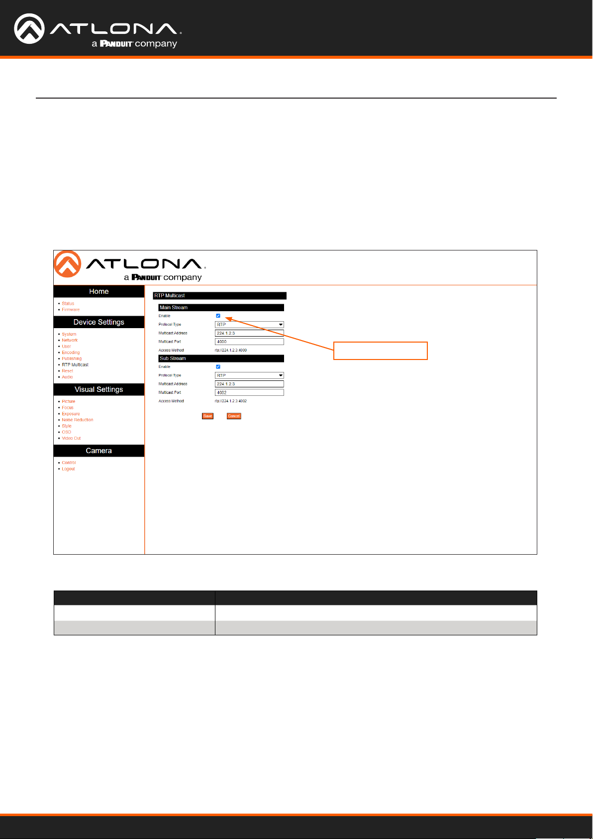
RTP Multicast
In order to for the stream to be published to a multicast address, follow the procedure below.
1. Login to the web server.
2. Click RTP Multicast in the side menu bar.
3. Click the Enable checkbox to enable the Main Stream and/or Sub Stream. When enabled, the checkbox will
contain a check mark.
Enable checkbox
4. Click the Protocol Type drop-down list to select the protocol type. Enter the host port in the Host Port eld.
Protocol Description
RTP Real Time Protocol
TS Transport Stream (MPEG-TS)
5. Enter the multicast address in the Multicast Address eld.
6. Enter the multicast port in the Multicast Port eld.
7. Click the Save button to commit changes.
Refer to the next page for conguration examples.
AT-HDVS-CAM-HDBT
28
Page 29

Conguration and Management Interfaces
Web Server
Main operation of the AT-HDVS-CAM-HDBT is handled through the built-in web server. In order to access the web
server, the IP address of the unit must be known.
Registration
1. Launch a desired web browser and enter the IP address of the AT-HDVS-CAM-HDBT in the address bar.
2. Enter the desired username in the User Name eld. In the example below, the username admin is used.
3. Enter the desired password in the Password eld. All passwords will be masked, when entered.
IMPORTANT: The password must contain a minimum of 8 characters, including: 1 uppercase
character, 1 lowercase character, and 1 number.
4. Verify the password by entering it in the Re-enter password eld.
5. Click the Register button.
6. The Login page will be displayed.
7. Registration is complete.
AT-HDVS-CAM-HDBT
29
Page 30
Conguration and Management Interfaces
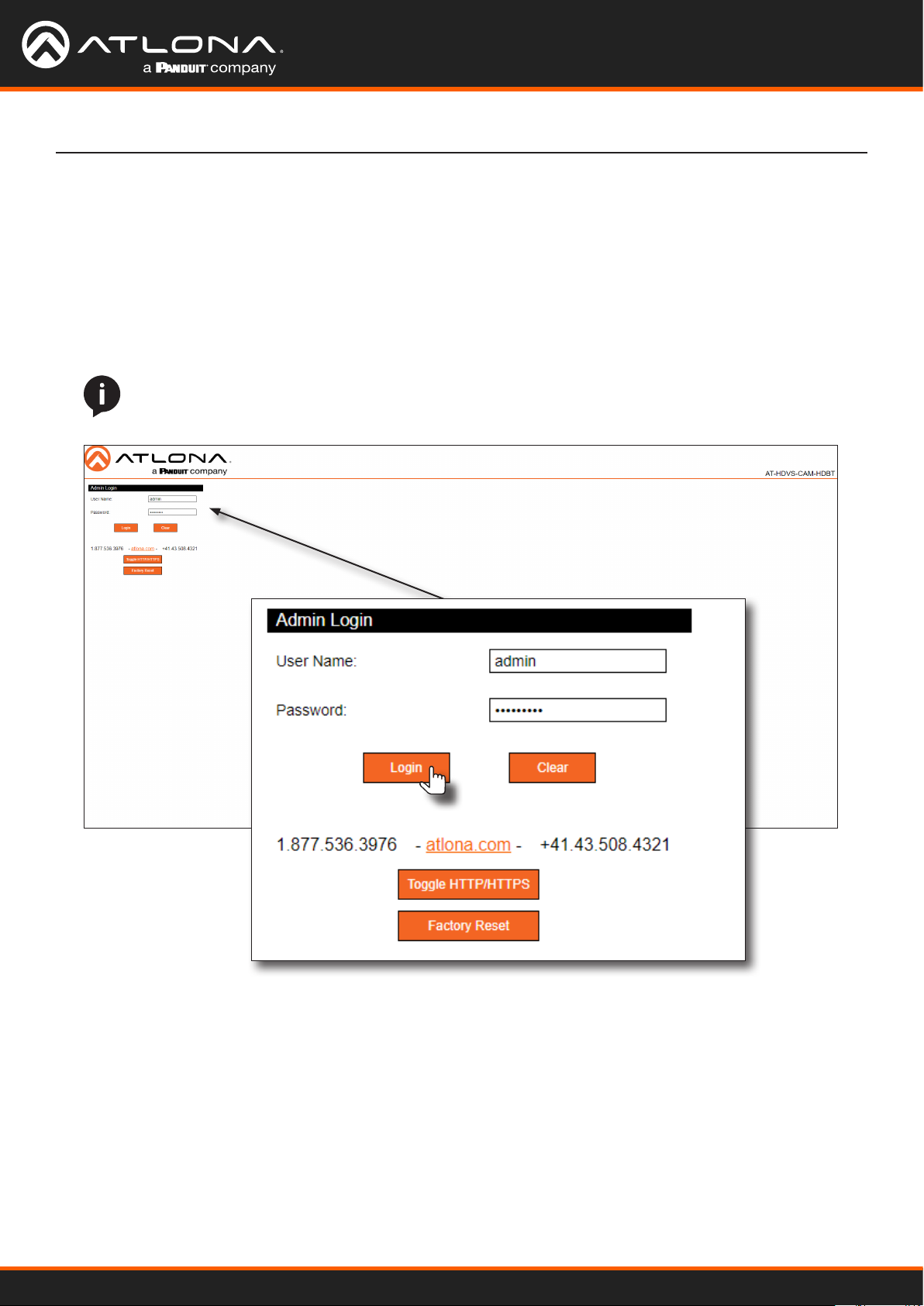
Logging In
Before logging in to the web server, make sure the registration process has been completed. Refer to Registration
(page 29) for more information.
1. Launch the desired web browser and enter the IP address of the AT-HDVS-CAM-HDBT in the address bar.
2. Enter the correct username and password in the respective elds. To clear the User Name and Password elds,
click the Clear button.
NOTE: If using a secure connection, click the Toggle HTTP/HTTPS button.
3. Click the Login button.
4. The Info page will be displayed and the login process is complete.
AT-HDVS-CAM-HDBT
30
Page 31
Conguration and Management Interfaces
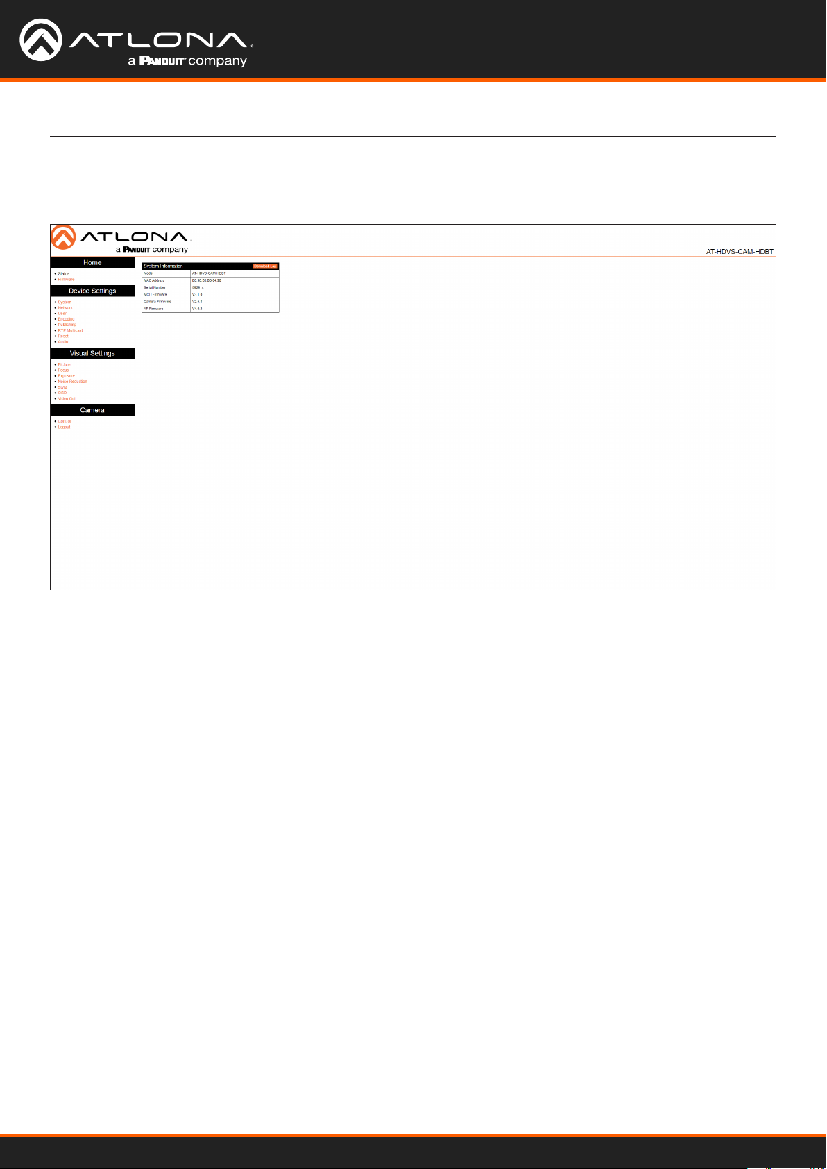
Status Page
The Status page provides basic information about the AT-HDVS-CAM-HDBT, including the software version.
Model
The model of the unit.
MAC Address
The hardware MAC address of the unit.
Serial Number
The serial number of the unit.
MCU Version
The version of MCU rmware.
Camera Firmware
The version of camera rmware.
AF Firmware
The version of rmware which controls Auto-Focus.
Download Log
Click this button to download the information in the System Information group, to an Excel le.
AT-HDVS-CAM-HDBT
31
Page 32

Firmware Page
Conguration and Management Interfaces
Firmware Status - System
MCU
The version of MCU rmware.
Camera
The version of camera rmware.
Auto Focus
The version of rmware which controls Auto-Focus.
Firmware Update
Update File
Displays the le currently selected for the update process.
Browse
Click this button to select the desired rmware le for the update process.
Upgrade
Click this button to begin the rmware update process.
AT-HDVS-CAM-HDBT
32
Page 33
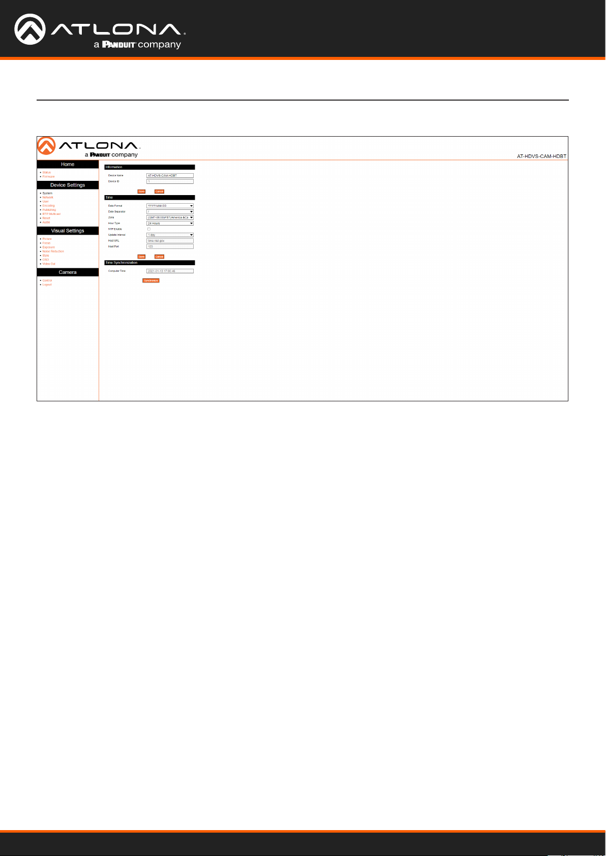
System Page
Conguration and Management Interfaces
Information
Device Name
Displays the model of the unit.
Device ID
The device ID.
Save
Click this button to commit changes under this section.
Cancel
Click this button to abort changes under this section.
Time
Date Format
Displays the le currently selected for the update process.
Data Separator
Click this drop-down list to specify the separator between month, day, and year.
Zone
Click this drop-down list to select the desired time zone.
Hour Type
Click this drop-down list to switch the time format between 12-hour and 24-hour clocks.
NTP
Click this check box to enable the use of an external NTP server.
AT-HDVS-CAM-HDBT
33
Page 34

Conguration and Management Interfaces
Update Interval
Click this drop-down list to select the time interval (in days), which the camera will poll the NTP server. This eld is
only active if the NTP check box is marked with a checkmark.
Host URL
Specify the NTP server address in this eld. This eld is only active if the NTP check box is marked with a
checkmark.
Host Port
Specify the NTP port in this eld. This eld is only active if the NTP check box is marked with a checkmark.
Save
Click this button to commit changes under this section.
Cancel
Click this button to abort changes under this section.
Time Synchronization
Computer Time
Displays the current time on the computer.
Synchronize
Click this button to synchronize the computer time.
AT-HDVS-CAM-HDBT
34
Page 35

Network Page
Conguration and Management Interfaces
Network Settings
DHCP
Switch between DHCP (ON) and static (OFF).
IP Address
Specify the IP address of the AT-HDVS-CAM-HDBT in this eld. This eld is only active if DHCP is set to OFF.
Subnet
Specify the IP subnet mask in this eld. This eld is only active if DHCP is set to OFF.
Gateway
Specify the default gateway (router) address in this eld. This eld is only active if DHCP is set to OFF.
MAC Address
Displays the MAC address of the AT-HDVS-CAM-HDBT.
Host Name
Specify the host name of the AT-HDVS-CAM-HDBT in this eld. The default host name will be HDVS-CAM-[last six
digits of MAC address].
Save
Click this button to commit changes under this section.
Cancel
Click this button to abort changes under this section.
AT-HDVS-CAM-HDBT
35
Page 36

Conguration and Management Interfaces
Port Settings
Enter the required port number in each of these elds. Each eld contains the default port settings. Available values
are from 0 to 65535.
Save
Click this button to commit changes under this section.
Cancel
Click this button to abort changes under this section.
DNS Settings
Preferred
Enter the primary DNS server address in this eld.
Alternative
Enter the failover DNS server address in this eld.
AT-HDVS-CAM-HDBT
36
Page 37

User Page
Conguration and Management Interfaces
User
User Name
Enter the desired user name in this eld.
New password
Enter the new password in this eld.
Re-enter password
Conrm the new password by entering it in this eld.
Save
Click this button to commit changes under this section.
Cancel
Click this button to abort changes under this section.
AT-HDVS-CAM-HDBT
37
Page 38
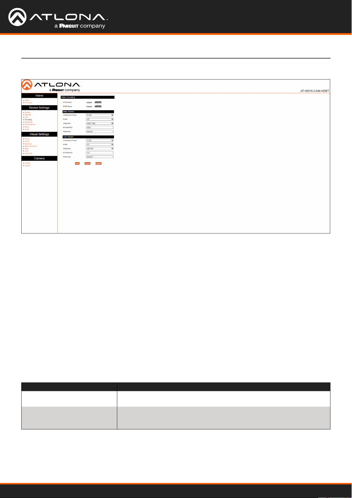
Encoding Page
Conguration and Management Interfaces
Video Encoding
RTSP Server
Enable / disable the RTSP protocol.
RTMP Server
Enable / disable the RTMP protocol.
Main Stream / Sub Stream
These settings aect the main stream, which is the primary video feed and provides the highest quality video.
This stream is used by a digital recorder when saving footage to hard disk. Adjusting these settings will aect the
recording size and available recording time on the hard disk.
Sub Stream is the secondary video feed and provides a lower quality video stream. This stream is used to stream
video to computers and mobile devices. Adjusting these settings will aect the bandwidth of the stream.
Compressed Format
Click this drop-down list to select the desired video codec.
Format Description
H.264 (AVC) Advanced Video Codec - Industry-standard codec that provides good-quality
compressed video output.
H.265 (HVEC) High-Eciency Video Coding - Provides a higher compression ratio than
H.264, thus reducing the bandwidth necessary for high-resolution (2K/4K)
video capture.
AT-HDVS-CAM-HDBT
38
Page 39

Conguration and Management Interfaces
Compressed Format
Click this drop-down list to select the desired prole.
Prole Description
BP Baseline Prole - Supports a limited set of processes and is designed to meet
the needs of mobile devices.
MP Main Prole - Supports a good number of processes and is typically used for
devices such as set-top boxes.
HP High Prole - Supports all processes of H.264 and targets FullHD (1080p) ap-
plications such as Blu-ray and satellite streams.
Image Size
Click this drop-down list to select the desired resolution. These resolutions are available for all codecs and proles.
Resolution
1920x1080 1280x720 640x480
Bit Rate (kb/s)
Enter the desired bit rate in this eld.
Encoding Protocol Bit Rate Range
H.264 64 ... 20480 kb/s
H.265 64 ... 40960 kb/s
Stream Key
Enter the stream key in this eld. This key (code) is used to identify the stream, allowing the stream to be displayed
on a web site.
Save
Click this button to commit changes.
Cancel
Click this button to abort changes.
Default
Click this button to restore default settings.
AT-HDVS-CAM-HDBT
39
Page 40

Publishing Page
Conguration and Management Interfaces
Main Stream / Sub Stream
These settings aect the main stream, which is the primary video feed and provides the highest quality video.
Sub Stream is the secondary video feed and provides a lower quality video stream. This stream is used to stream
video to computers and mobile devices.
Enable
Click this check box to enable the main stream / sub stream. When a stream is enabled, the check box will be
checked.
Protocol Type
This drop-down list is set to RTMP and cannot be changed.
Host Address
Specify the IP address or stream URL in this eld.
Host Port
Specify the port in this eld.
Stream Key
Specify the stream key in this eld.
Save
Click this button to commit changes.
Cancel
Click this button to abort changes.
AT-HDVS-CAM-HDBT
40
Page 41

RTP Multicast Page
Conguration and Management Interfaces
Main Stream / Sub Stream
These settings aect the main stream, which is the primary video feed and provides the highest quality video.
Sub Stream is the secondary video feed and provides a lower quality video stream. This stream is used to stream
video to computers and mobile devices.
Enable
Click this check box to enable the main stream / sub stream. When a stream is enabled, the check box will be
checked.
Protocol Type
Click this drop-down list to set the protocol.
Protocol Description
RTP Real Time Protocol
TS Transport Stream (MPEG-TS)
Multicast Address
Specify the multicast IP address of the stream in this eld.
Multicast Port
Specify the port in this eld.
Access Method
Displays the fully-qualied URL of the stream, based on the above settings.
Save
Click this button to commit changes.
Cancel
Click this button to abort changes.
AT-HDVS-CAM-HDBT
41
Page 42
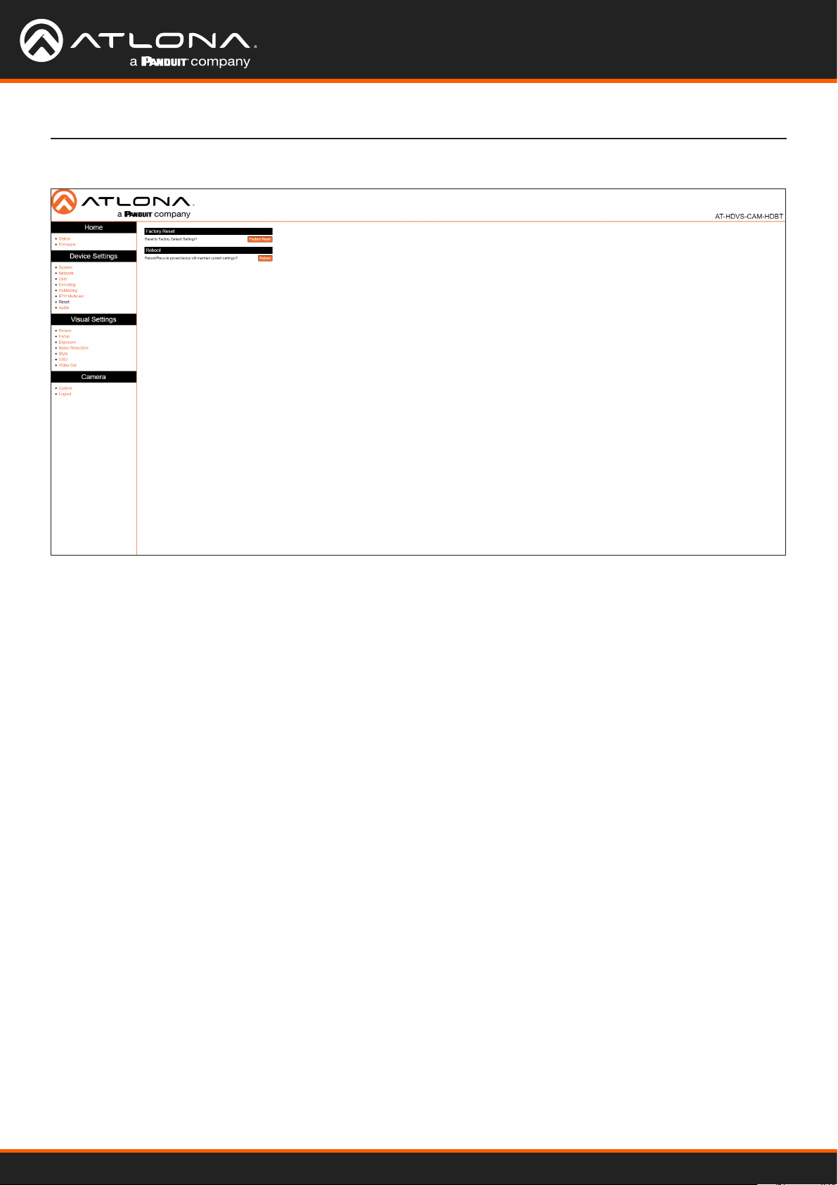
Reset Page
Conguration and Management Interfaces
Factory Reset
Factory Reset
Click this button to factory-reset the AT-HDVS-CAM-HDBT.
Reboot
Reboot
Click this button to reboot/power-cycle the AT-HDVS-CAM-HDBT.
AT-HDVS-CAM-HDBT
42
Page 43

Audio Page
Conguration and Management Interfaces
Audio Conguration
Enable
Click this check box to enable audio conguration. When enabled, this check box will be checked.
Encoding Type
Click this drop-down list to select the audio codec.
Encoding Bit Rate Range
AAC Advanced Audio Encoding - Industry-standard lossy compression for digital
audio. Exhibits a higher sound quality than MP3.
MP3 MPEG-1/MPEG-2 Audio Layer III - Uses lossy data-compression, discarding
some data, resulting in lower-bandwidth, high-quality audio.
Sample Rate
Selects the sample rate in Hertz. Available options are 16000 (16 kHz), 32000 (32 kHz), 44100, (44.1 kHz) and 48000
(48 kHz).
Sample Bits
This option is set to 16 and cannot be changed.
Bit Rate
Selects the bit rate. Available options are 32 kbps, 48 kbps, 64 kbps, 96 kbps, and 128 kbps.
Channel
Selects the number of channels that are heard on the output.
Encoding Bit Rate Range
Mono Single-channel audio stream.
Stereo Two-channel (L/R) audio stream.
AT-HDVS-CAM-HDBT
43
Page 44

Input Volume
Click and drag this slider to adjust the input volume.
Save
Click this button to commit changes.
Cancel
Click this button to abort changes.
Conguration and Management Interfaces
AT-HDVS-CAM-HDBT
44
Page 45
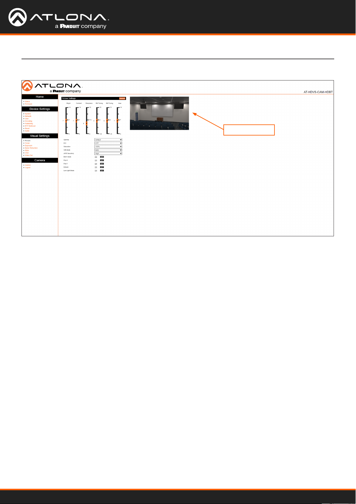
Picture Page
Conguration and Management Interfaces
Image preview
Picture Settings
Bright
Click and drag this slider to adjust the picture brightness between a value of 0 and 14. Larger values produce a
brighter image. The default setting is 6.
Contrast
Click and drag this slider to adjust the picture contrast between a value of 0 and 14. Larger values produce a higher
contrast image. The default setting is 7.
Sharpness
Click and drag this slider to adjust the picture sharpness between a value of 0 and 14. Larger values will produce a
sharper image. The default setting is 7.5.
RG Tuning
Click and drag this slider to adjust the red-gain tuning between a value of -10 and 10. Use this feature to reduce
unwanted red colors. Larger values will introduce a red tint to the image. The default setting is 0.
BG Tuning
Click and drag this slider to adjust the blue-gain tuning between a value of -10 and 10. Use this feature to reduce
unwanted blue colors. Larger values will introduce a blue tint to the image. The default setting is 0.
Hue
Click and drag this slider to adjust the picture hue between a value of 0 and 14. Larger values will introduce more red
into the image, while smaller values will introduce more blue into the image. The default setting is 7.
Gamma
Click this drop-down list to select the desired gamma setting. Larger values will display a darker image. The default
setting is Default.
DCI
Click and drag this slider to adjust the dynamic contrast of the image. Larger values produce a higher contrast
image. The default setting is OFF.
AT-HDVS-CAM-HDBT
45
Page 46
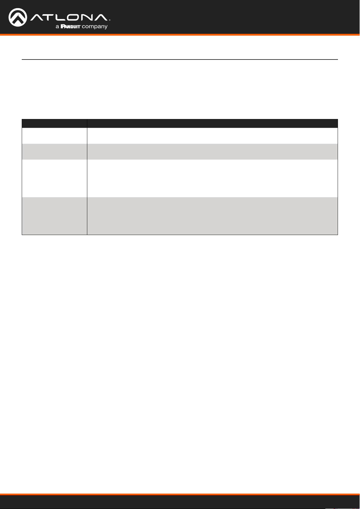
Conguration and Management Interfaces
Saturation
Click this drop-down list to select the desired saturation value. Available values are between 60% and 200% in
increments of 10. Larger values will produce and image with a higher color contrast. The default setting is 100%.
WB Mode
Click this drop-down list to select the desired white balance setting.
WB Mode Description
Auto Automatically adjusts white balance based on the captured image. This is the default
setting.
Manual Permits manual white balance setting using the RG (Red Gain), BG (Blue Gain), and Hue
slider settings.
OnePush When selected, this option will display an Adjust button. Click the Adjust button to allow
the camera to make automatic white balance adjustment of the captured image. This
setting is dierent than Auto, in that the Auto setting will constantly adjust the image,
based on the lighting. The OnePush option, allows the white balance to be set, based on
the current lighting, much like setting the white balance on a DSLR camera.
VAR When selected, a Color Temp drop-down list will be displayed below the WB Mode
drop-down list. Color temperature (in Kelvin) can be selected from the Color Temp drop-
down list. The Color Temp drop-down list provides values from 2400K to 7100K, in
increments of 100K. The Hue slider can also be used to provide granular tuning of the
color temperature.
AWB Sensitivity
Click this drop-down list to select the auto-white balance sensitivity. AWB automatically color-corrects the captured
image, by analyzing the light reaching the camera sensor, and attempts to correct for any color shifts that may
otherwise take place.
B&W Mode
Setting this value to ON will remove color information from the image.
Flip-H
When set to ON, the image will be horizontally ipped.
Flip-V
When set to ON, the image will be vertically ipped.
DZoom
When set to ON, dynamic zoom will be enabled.
Low-Light Mode
When set to ON, low-light mode is enabled. This provides better image quality in low-light environments.
AT-HDVS-CAM-HDBT
46
Page 47
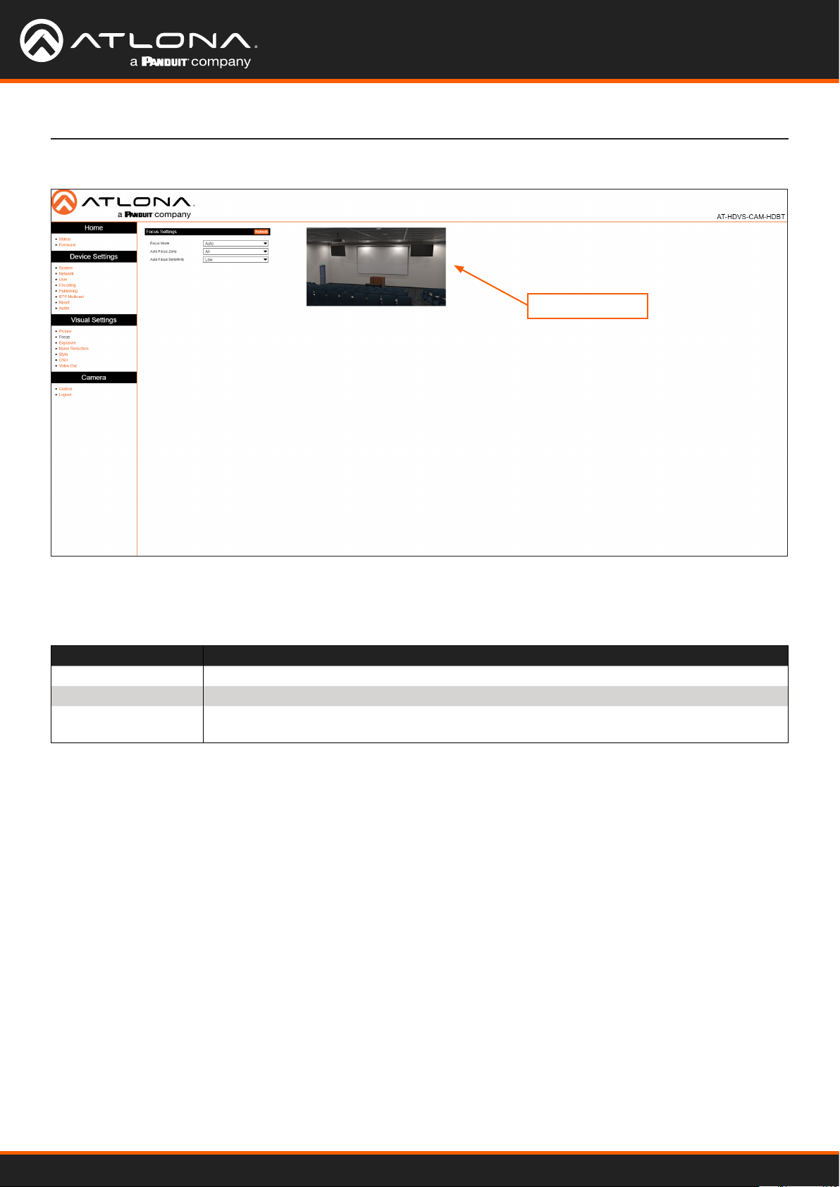
Focus Page
Conguration and Management Interfaces
Image preview
Focus Settings
Focus Mode
Click this drop-down list to select the desired focus mode.
Focus Mode Description
Auto Automatically adjusts focus based on the captured image.
Manual Permits manual focus control.
OnePush When selected, this option will adjust the focus based on the currently captured image.
The same focus setting will be applied to all other camera movement.
Auto Focus Zone
Click this drop-down list to select the zone where auto focus will be applied. Available options are Top, Center,
Bottom, and All. The default setting is All.
Auto Focus Sensitivity
Click this drop-down list to select the auto focus sensitivity. Available options are Low, Med, and High. The default
setting is Low.
AT-HDVS-CAM-HDBT
47
Page 48
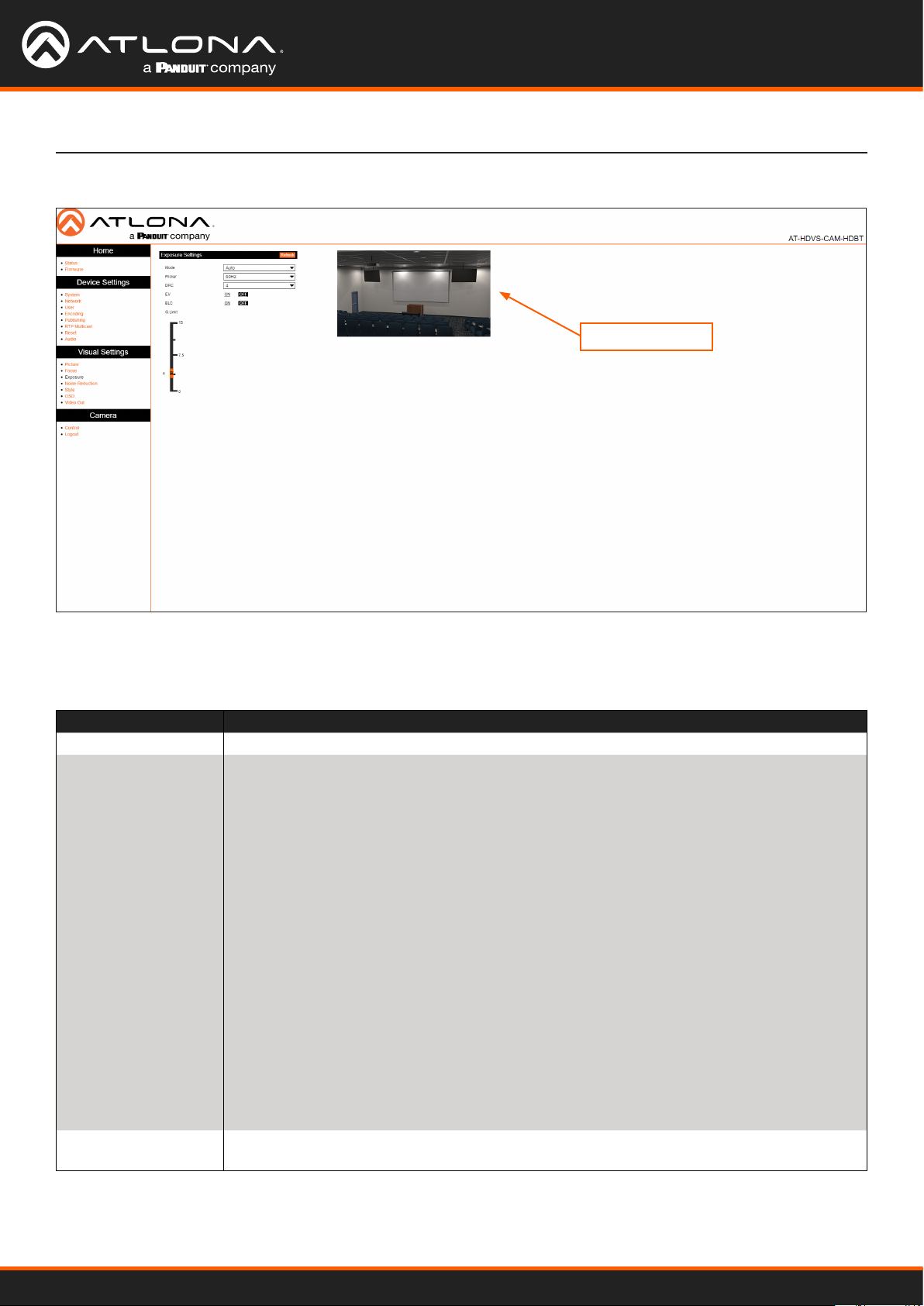
Exposure Page
Conguration and Management Interfaces
Image preview
Exposure Settings
Mode
Click this drop-down list to select the desired mode.
Mode Description
Auto Automatically adjusts the exposure, based on available light.
Manual Permits manual exposure control. When selected, the following options will be available:
Iris, Shutter, and Gain. These options are similar to aperture, shutter speed, and ISO
speed in a DLSR camera.
Iris: Click this drop-down list to select the f-stop value. The larger the value, the smaller
the diameter of the iris (aperture). Larger values permit less light into the camera sensor,
making the image darker.
Shutter: Click this drop-down list to select the shutter speed. This is the time interval
required to open and close the shutter during each frame of video. Larger values (fast
shutter speeds) will allow less light to enter the camera sensor, producing darker images,
but will produce crisp video. Low values (slow shutter speeds) will allow more light to enter
the camera sensor, allowing for brighter images, but will make moving objects appear
blurry.
Gain: Click and drag this slider to adjust the gain. Gain is similar to adjusting the ISO
(image noise) values on a DSLR. Larger values will increase the brightness of the image
in low-light environments, but will introduce noise (grain) into the image. Smaller values
decrease the image brightness in bright/outside environments and introduce less noise into
the image.
SAE Shutter Automatic Exposure (SAE). When selected, this option will measure the incoming
light and automatically adjust the iris (aperture) based on the selected shutter speed.
AT-HDVS-CAM-HDBT
48
Page 49

Conguration and Management Interfaces
Mode Description
AAE Aperture Automatic Exposure (AAE). When selected, this option will measure the incoming
light and automatically adjust the shutter speed based on the selected iris (aperture)
setting.
Bright When selected, a Bright slider will be displayed. The larger the value, the brighter the
image.
Flicker
Click this drop-down list to set the icker setting. Available values are 50 Hz, 60 Hz, and OFF. The default setting is
OFF. Note that this option is not available when Mode is set to Manual.
DRC
Dynamic Range Control. DRC is the measurement between maximum and minimum values in an image. Larger
values attempt to discern between dierent color values in the image.
EV
Exposure Value. This option essentially combines both shutter speed and iris (aperture) into a single value. However,
unlike independently adjusting shutter speed and iris settings, this value restricts the eect to the image exposure.
When this option is set to ON, then an EV Level slider bar will be displayed.
BLC
Back Light Compensation. BLC is a feature which automatically adjusts the exposure control of the camera. When
enabled, BLC will attempt to increase the ambient foreground light and “darken” any background light.
For example, a subject standing in front of a window in the daytime, will produce a silhouetted eect. Enabling BLC
will compensate for the dierence in lighting by enhancing the foreground lighting on the subject.
AT-HDVS-CAM-HDBT
49
Page 50
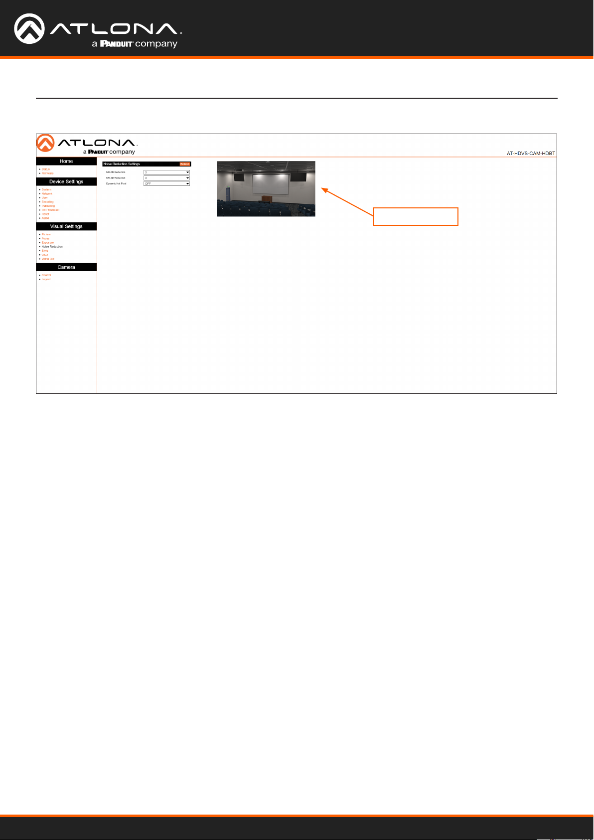
Noise Reduction Page
Conguration and Management Interfaces
Image preview
Noise Reduction Settings
Image noise is dened as pixels which do not represent any color. Image noise is usually present when shooting in
low-light environments.
NR-2D
Click this drop-down list to select the desired 2D noise reduction setting. Apply 2D noise to environments where
there is a lot of motion, such as live events. Available values are OFF, 1 ... 7, and Auto.
NR-3D
Click this drop-down list to select the desired 3D noise reduction setting. Apply 3D noise reduction to environments
where there is no movement. Available values are OFF, 1 ... 7, and Auto.
Dynamic Hot Pixel
Hot pixels are sometimes referred to as “stuck” pixels, and appear bright “specks” in the image. Hot pixels tend to
appear when using slower shutter speeds and/or high gain settings. This feature will eliminate these pixels. Click the
drop-down list to select the desired setting. Larger values will be more aggressive at removing hot pixels. Available
values are: OFF and 1 ... 5.
AT-HDVS-CAM-HDBT
50
Page 51
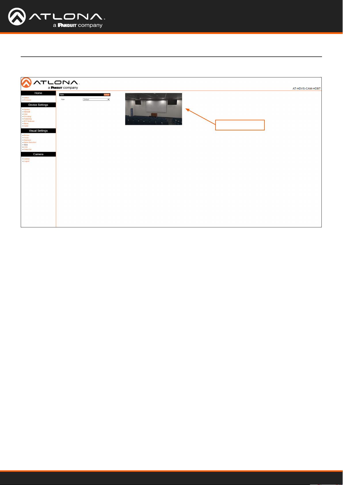
Style Page
Conguration and Management Interfaces
Image preview
Style
Style
Click this drop-down list to select the desired image style. Style is an image preset, which produces a desired look.
Available options are: Default, Normal, Clarify, Bright, and Soft.
AT-HDVS-CAM-HDBT
51
Page 52
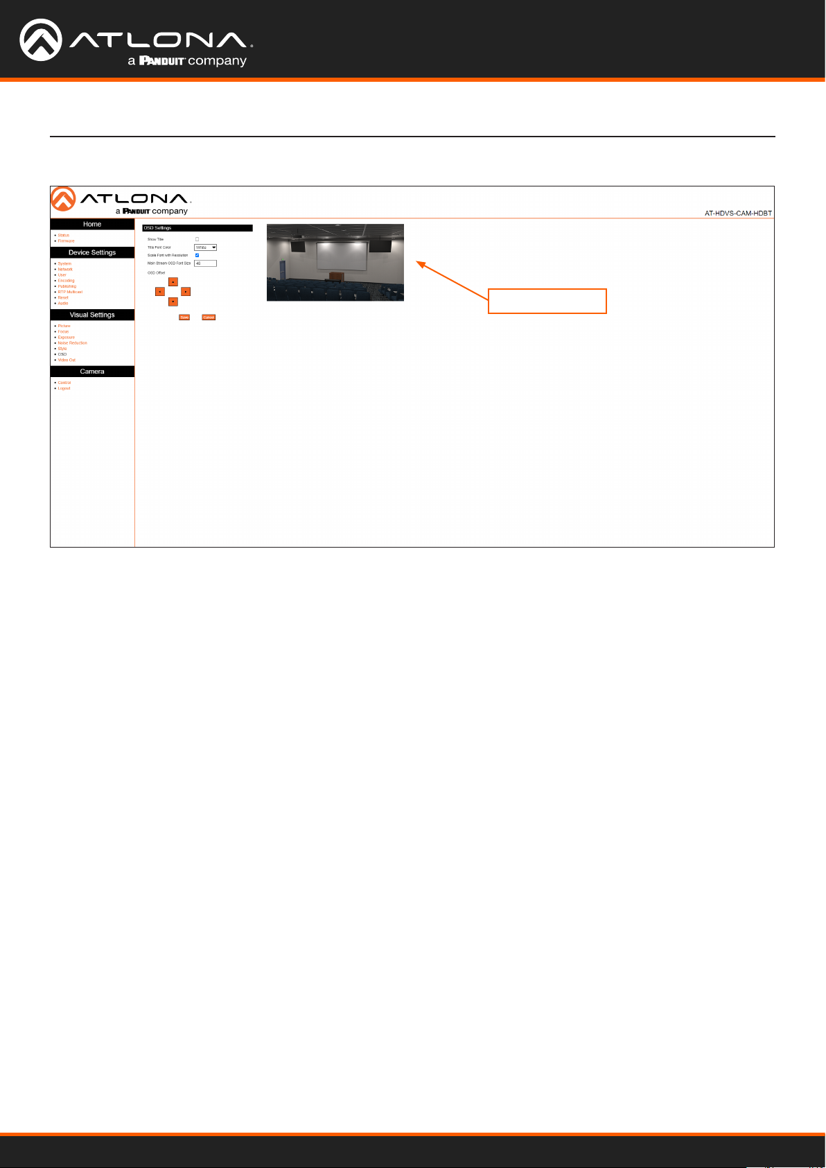
OSD Page
Conguration and Management Interfaces
Image preview
OSD Settings
Show Title
Click this check box to display the device name in the upper-left corner (default position) of the screen. When
enabled, the check box will display a check mark. To change the device name, refer to the System > Information >
Device Name on the System Page (page 33). Click the Save button to have changes take eect.
Title Font Color
Click this drop-down list to set the font color of the title. Available options are White, Black, Yellow, Red, and Blue.
Scale Font with Resolution
Click this check box to scale the font title when the resolution changes. When enabled, the check box will display a
check mark.
Main Stream OSD Font Size
Specify the title font size in this eld. When enabled, the check box will display a check mark. Click the Save button
to have changes take eect.
OSD Oset
Click these arrows to position the title font on the screen. Click the Save button to have changes take eect.
Save
Click this button to commit changes.
Cancel
Click this button to abort changes.
AT-HDVS-CAM-HDBT
52
Page 53

Video Out Page
Conguration and Management Interfaces
Video Out
Video Out Format
Click this drop-down list to select the desired output resolution. Available resolutions are listed in the table below.
Format
1080P60 720P60
1080P50 720P50
1080P30 1080P59.94
1080P25 1080I59.94
1080I60 1080P29.97
1080I50 720P59.94
Save
Click this button to commit changes.
AT-HDVS-CAM-HDBT
53
Page 54

Control Page
Conguration and Management Interfaces
Image preview
Camera Control
Refer to Controlling the Camera (page 16) for more information.
Pan-Tilt-Zoom
Click these arrows to adjust the pan, tilt, and zoom of the camera.
Focus Mode
Click this drop-down list to select the desired focus mode.
AT-HDVS-CAM-HDBT
54
Page 55

IR Remote and OSD
IR Remote Control
The AT-HDVS-CAM-HDBT comes with an IR remote control for full control of the camera and use of the OSD menu.
Power
SET
CAMERA SELECT
1
2 3
4
Toggle the camera on and o with the power button. Press and hold for 3 seconds to
place the camera into standby mode.
Number buttons
Used in the selection or creation of camera presets.
1 2 3
4 5 6
7 8 9
8 #
*
+
AUTO
FOCUS ZOOM
_ _
MANUAL
SET
PRESET
HOME
BLC
ON/OFF
F1 F2 F3 F4
+
CLEAR
PRESET
MENU
Focus
Adjust the focus of the camera using the + and - buttons.
Auto
Switch the camera focus mode to auto.
Manual
Switch the camera focus mode to manual.
Zoom
Zoom in (+) or out (-) using these buttons.
Set Preset
Set the camera into position then press the Set Preset button followed by a number
key (0-9) to set that position to a preset.
Clear Preset
Press clear preset followed by a number key to erase the preset set to that number.
Arrow buttons
Use the arrow buttons to adjust the camera position or navigate within the OSD menu.
Home buttons
Returns the camera to the middle position.
BLC ON/OFF
Toggles backlight compensation on or o.
Menu
Use to pull up the OSD menu.
OSD
The OSD will display after pressing the MENU button.
OSD
Language English
Chinese
Setup Protocol Auto Visca PELCO-D PELCO-P (Options)
Visca Address 1 1
Visca Address O O
PELCO-P Address 1 1
PELCO-D Address 1 1
Baudrate 9600 9600 9600 9600 9600,
AT-HDVS-CAM-HDBT
55
Page 56

IR Remote and OSD
OSD Cont.
Camera Exposure Mode Auto Bright AAE SAE Manual
Bright 7 0 to 23
IRIS F1.8 F1.8 F1.8, F2.0, F2.4,
Shutter 1/100 1/100 1/25, 1/30, 1/50,
EV ON ON, OFF
EV Level 0 -7 to 7
BLC OFF ON, OFF
Flicker 50Hz 50Hz 50Hz OFF, 50Hz, 60Hz
G. Limit 4 4 4 0 to 15
DRC 4 4 4 4 Close, 1 to 8
Color WB Mode Auto Onepush Manual 7000K 6500K 5500K, 5000K,
RG Tuning 0 RG145 -10 to 10
BG Tuning 0 BG56 -10 to 10
Saturation 100% 100% 100% 100% 100% 60, 100, 110, 120,
Hue 7 7 7 7 7 0 to 14
AWB Sens High High, Middle, Low
Image Brightness 6 0 to 14
Contrast 8 0 to 14
Sharpness 6 0 to 15
Flip-H OFF OFF, ON
Flip-V OFF OFF, ON
B&W Mode Color Color, B&W
Gamma 0.45 Default, 0.45, 0.50, 0.55, 0.63
DCI 2 Close, 1 to 8
Image Quality 0 0 to 5
Focus Focus Mode Auto Auto, Onepush, Manual
AF-Zone Center Center, Top, All, Bottom
AF-Sensitivity Low Low, High, Middle
Noise Reduction NR-2D 2 OFF, Auto, 1 to 7
NR-3D 4 OFF, 1 to 8
Dynamic Hot Pixel OFF OFF, 1 to 5
Style Clarity Clarity, Normal, Default, Soft, Bright
F2.8, F3.4, F4.0,
F4.8, F5.6, F6.8,
F8.0, F9.6, F11,
Close
1/60, 1/90, 1/100,
1/120, 1/180,
1/250, 1/325,
1/500, 1/1000,
1/2000, 1/3000,
1/4000, 1/6000,
1/10000
4500K, 4000K,
3500K, 3000K
200
AT-HDVS-CAM-HDBT
56
Page 57
IR Remote and OSD
OSD Cont.
P/T/Z Speed By Zoom ON ON, OFF
Zoom Speed 8 1 to 8
Acc Curve Slow Slow, Fast
Version MCU Version X.X.X 20YY-MM-DD
Camera Version X.X.X 20YY-MM-DD
AF Version X.X.X 20YY-MM-DD
Ethernet IP Address XXX.XXX.XXX.XXX e.g. 10.20.20.233
Subnet Mask XXX.XXX.XXX.XXX e.g. 255.255.255.0
Gateway XXX.XXX.XXX.XXX e.g. 10.20.20.1
Restore Default Restore Default? NO, YES - Restore Default Now...
Remote Functions
The included IR Remote Control provides a set of functions which can be used to change the behavior of the ATHDVS-CAM. Each function is invoked by sequentially pressing the following series of keys on the keypad.
Function Keystrokes
Clear all presets [#] + [#] + [#]
Flip video horizontally and vertically [*] + [#] + [9]
Reset username, password, and IP address [*] + [#] + [MANUAL]
Switch video format to 1080p60 [#] + [#] + [0]
Switch video format to 1080p50 [#] + [#] + [1]
Switch video format to 1080i60 [#] + [#] + [2]
Switch video format to 1080i50 [#] + [#] + [3]
Switch video format to 720p60 [#] + [#] + [4]
Switch video format to 720p50 [#] + [#] + [5]
Switch video format to 1080p30 [#] + [#] + [6]
Switch video format to 1080p25 [#] + [#] + [7]
Switch video format to 720p30 [#] + [#] + [8]
Switch video format to 720p25 [#] + [#] + [9]
AT-HDVS-CAM-HDBT
57
Page 58

Appendix
Using VLC Player
This section provides step-by-step instructions on how to display a stream using the VideoLAN VLC media player.
Before proceeding, make sure that both the Main Stream and Sub Stream are properly congured. Refer to the User
Manual for more information.
1. Launch VLC media player.
2. Click the Media > Open Network Stream...
3. Click the Network tab.
4. Refer to the RTP Multicast page in the AT-HDVS-CAM-HDBT web server, and locate the Access Method eld.
Copy this information into the provided eld within the VLC Network tab. Note that the Access Method elds
for the Main Stream and Sub Stream will dier. Make sure you specify the correct stream to broadcast.
Access Method
AT-HDVS-CAM-HDBT
58
Page 59

5. Click the Play button to begin streaming.
Appendix
VLC will begin buering the stream. Note that it may take a few moments for the network stream to be
displayed.
AT-HDVS-CAM-HDBT
59
Page 60

Appendix
Using Facebook Live
This section provides step-by-step instructions on how to display a stream using Facebook Live. Before proceeding,
make sure that both the Main Stream and Sub Stream are properly congured. Refer to the User Manual for more
information.
1. Launch a web browser and login to your Facebook account.
2. Click Live Video on the news feed page.
3. Under the Stream Setup tab, click Use Stream Key.
4. Under Live Stream Setup, click the Copy button, next to Server URL.
AT-HDVS-CAM-HDBT
60
Page 61
Appendix
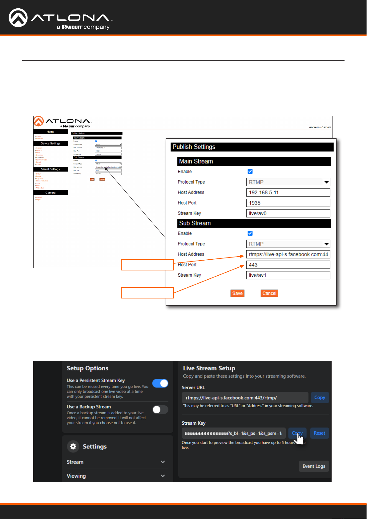
5. Go to the Publishing page of the AT-HDVS-CAM-HDBT web server.
6. Paste the contents from the Server URL eld, on Facebook, to the Host Address eld in the camera web
interface. Note that the contents of the Facebook Server URL eld can be placed under the Main Stream or
Sub Stream. Make sure that the contents are pasted into the correct eld.
Server URL
Host Port
7. Enter 443 in the Host Port eld, as shown. This step is required in order for the stream to work properly.
8. Return to the Facebook Stream Setup tab.
9. Click the Copy button, next to the Stream Key eld.
AT-HDVS-CAM-HDBT
61
Page 62
Appendix
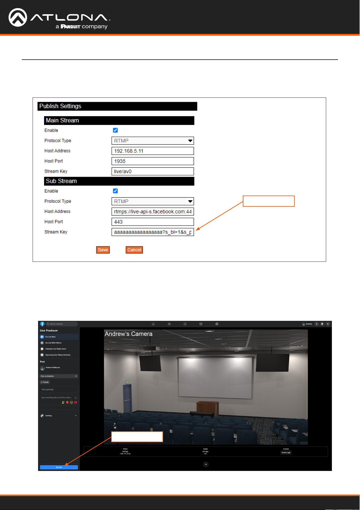
10. Paste the contents from the Stream Key eld, on Facebook, to the Stream Key eld in the camera web
interface. Make sure that the contents are pasted into the correct eld. Refer to the User Manual for the AT-
HDVS-CAM-HDBT for information on Main Stream and Sub Stream conguration.
Stream Key
11. Click the Save button to commit changes.
12. Return to the Facebook Stream Setup tab and scroll up to preview the video stream. Note that it may take a few
moments for the video stream to buer and be displayed.
13. To begin broadcasting the video, click the Go Live button, located in the bottom-left corner of the screen.
Go Live button
AT-HDVS-CAM-HDBT
62
Page 63
Appendix
Using YouTube Live
This section provides step-by-step instructions on how to display a stream using YouTube Live. Before proceeding,
make sure that both the Main Stream and Sub Stream are properly congured. Refer to the User Manual for more
information.
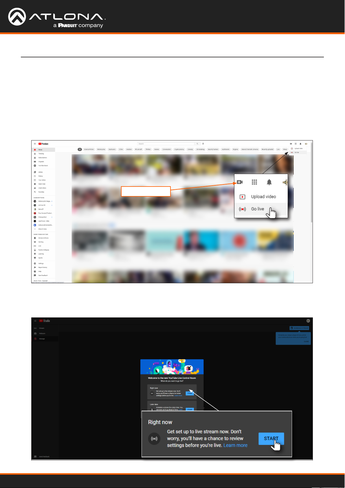
1. Launch a web browser and login to your YouTube account.
2. In the upper-right corner of the screen, click the Create icon (camera), then click Go Live.
Create icon
3. Under the YouTube Studio page, click the STAR T button next to either Right now or Later date. In this
example, the Right now option will be selected.
AT-HDVS-CAM-HDBT
63
Page 64

Appendix
4. The next screen will provide the option of selecting a Built-in webcam or Streaming software. Click the Go
button next to Streaming software.
5. Set the desired settings in the Edit stream dialog box.
6. Click the SAVE button to commit changes.
AT-HDVS-CAM-HDBT
64
Page 65
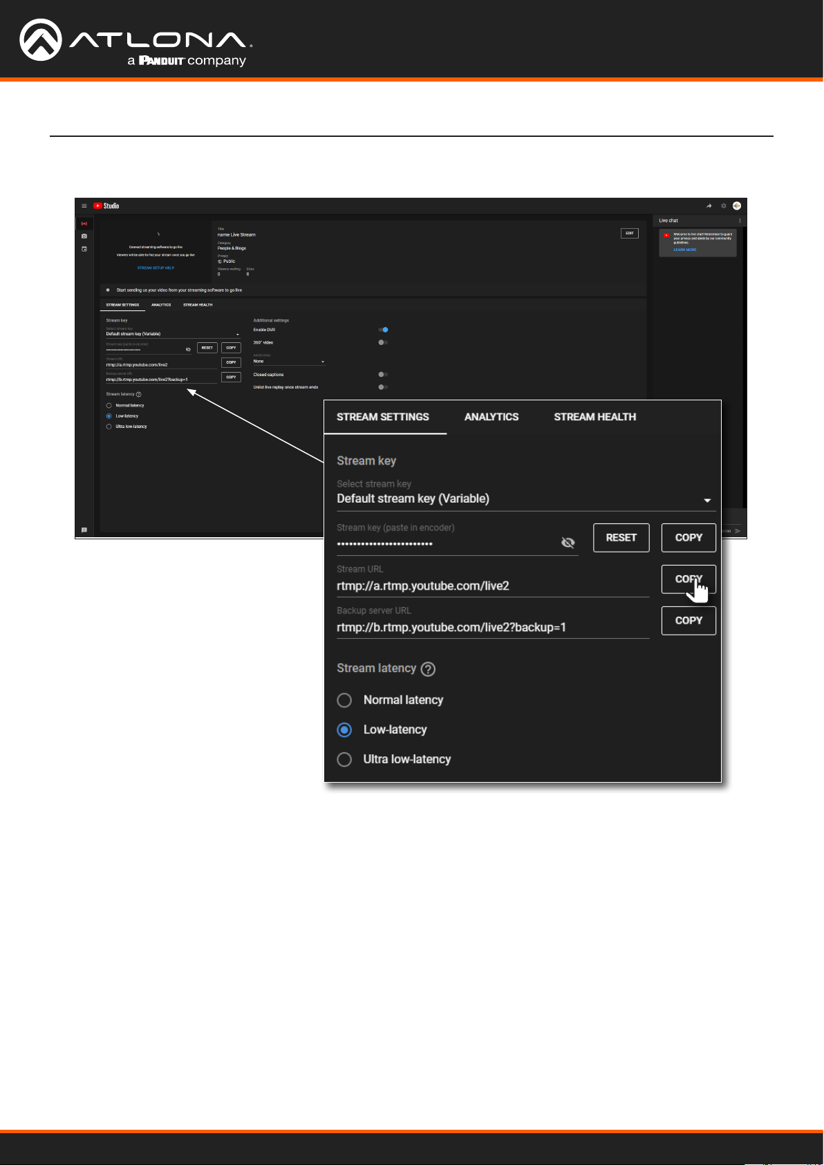
7. Click the COPY button, next to the Stream URL eld.
Appendix
8. Go to the Publishing page of the AT-HDVS-CAM-HDBT web server.
AT-HDVS-CAM-HDBT
65
Page 66

Appendix
9. Paste the contents from the Stream URL eld, on YouTube Live, to the Host Address eld in the camera web
interface. Note that the contents of the YouTube Live Stream URL eld can be placed under the Main Stream
or Sub Stream. Make sure that the contents are pasted into the correct eld. Refer to the User Manual for the
AT-HDVS-CAM-HDBT for information on Main Stream and Sub Stream conguration.
Stream URL
Host Port
10. Leave the Host Port eld set to 1935.
11. Return to the YouTube Live Stream Settings tab and click the COPY button, next to the Stream key eld.
AT-HDVS-CAM-HDBT
66
Page 67
Appendix
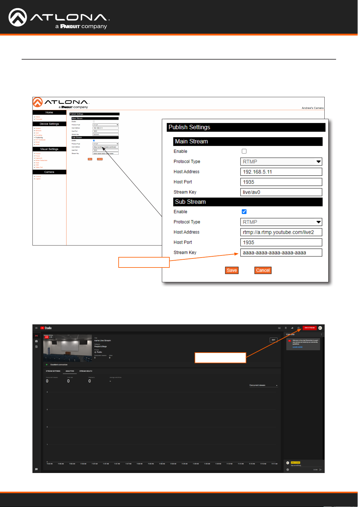
12. Paste the contents from the Stream key eld, on YouTube Live, to the Stream Key eld in the camera web
interface. Make sure that the contents are pasted into the correct eld. Refer to the User Manual for the AT-
HDVS-CAM-HDBT for information on Main Stream and Sub Stream conguration.
Stream Key
13. Click the Save button to commit changes.
14. Return to YouTube Live. The live stream preview will be displayed in the upper-left corner of the screen.
15. To stop the live stream, click the END STREAM button in the upper-right corner of the screen.
END STREAM
AT-HDVS-CAM-HDBT
67
Page 68

Specications
Video
Signal HDBaseT
HD 1920x1080p@60/59.97/50/30/29.97/25 Hz
1920x1080i@60/59.94/50 Hz
1280x720p@60/59.94/50 Hz
Color Space YUV, RGB
Chroma Subsampling 4:4:4, 4:2:2, 4:2:0
Audio
Audio Compression AAC, MP3
Sample Rate 16 kHz, 32 kHz, 44.1 kHz, 48 kHz
Sample Bits 16
Bit Rate 32 kbps - 128 kbps
Channels Mono, Stereo
Streaming
Video Compression H.264 / H.265
Protocol TCP, UDP, RTMP, RTSP
Bitrate 46 kbps - 40960 kbps
Compression Proles BP, MP, HP
Bitrate Control VBR
Multi-Stream Main Stream / Sub Stream (simultaneous stream output)
Latency 175 ms
Appendix
(1)
Camera
Sensor 1/2.8” HD CMOS
Eective Pixels 16:9, 2.07 MP
Optical Zoom f = 4.7 ~ 47 mm
View Angle 6.43° (telephoto), 60.9° (wide-angle)
Av f/1.6 - f/3.0
Digital Zoom 10X
Minimum Illumination 0.5 lm (f/1.8 with AGC On)
DNR 2D / 3D
White Balance Auto / Manual / One Push / 3000 K / 4000 K / 5000 K / 6500 K
Focus Auto / Manual
Aperture Auto / Manual
Electronic Shutter Auto / Manual
BLC ON / OFF
WDR O / Dynamic Level Adjustment
Camera
Video Adjustment Brightness, Color, Saturation, Contrast, Sharpness, B/W Mode, Gamma Curve
SNR > 55 dB
AT-HDVS-CAM-HDBT
68
Page 69
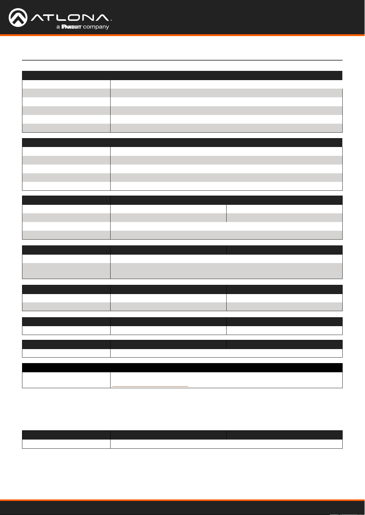
PTZ
Pan Rotation ± 170°
Tilt Rotation -30° ~ +90°
Pan Control Speed 0.1 - 180° / sec
Tilt Control Speed 0.1 - 80° / sec
Preset Speed Pan: 60° / sec, Tilt: 30° / sec
Preset Number 255 (10 presets using the included IR remote control)
Connectors
HDBaseT OUT 1 x RJ45
LAN 1 x RJ45, 100Base-T
AUDIO IN 1 x 3.5 mm, stereo
RS-232 1 x 9-pin DIN
12VDC 1 x HEC3800
Temperature Fahrenheit Celsius
Operating 14 to 122 -10 to 50
Storage -14 to 140 -10 to 60
Operating Humidity (RH) 20% to 80%, non-condensing
Storage Humidity (RH) 20% to 95%, non-condensing
Appendix
Power
Consumption 12 W
Supply Input: 110 - 220 V AC, 50/60 Hz
Output: 12 V DC, 1 A
Dimensions (H x W x D) Inches Millimeters
Unit 6.59 x 5.90 x 5.90 167.5 x 150 x 150
Power Supply (AT-PS-122-NL) 1.26 x 1.97 x 3.7 32.05 x 50 x 94
Weight Pounds Kilograms
Device 3.08 1.4
Certication
Device CE, FCC
Warranty
Device To view the product warranty, use the following link:
https://atlona.com/warranty
Accessories
SKU Title
AT-HDVS-CAM-CMNT Ceiling Mount Kit for AT-HDVS-CAM
Footnotes
(1) Tested using VLC media player connected to the camera.
AT-HDVS-CAM-HDBT
69
Page 70

atlona.com • 408.962.0515 • 41.43.508.4321
US International
35286-R5
 Loading...