

Page 1
Installation Guide
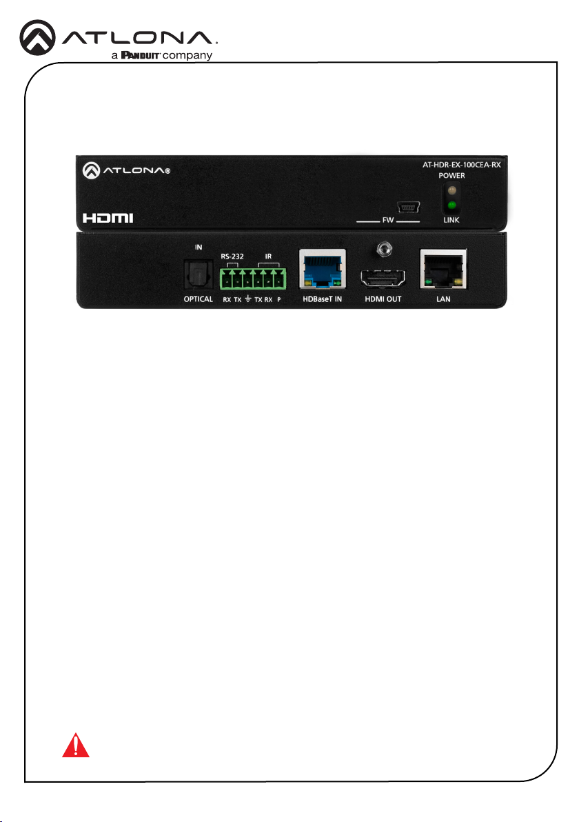
AT-HDR-EX-100CEA-RX
4K HDR HDMI over 100 M HDBaseT™ RX
with Ethernet, Control, PoE, and Return Audio
AT-HDR-EX-100CEA-RX
The Atlona AT-HDR-EX-100CEA-RX is a HDBaseT™ receiver for 4K and high dynamic range
(HDR) content. It supports extension of 4K/UHD video @ 60 Hz with 4:4:4 chroma sampling
plus HDR data, multi-channel audio, Ethernet, control signals, and power up to 330 ft. (100 m)
over Category 6/6A cable. The HDR-EX-100CEA-RX is ideal for use with the AT-HDR-CAT-4ED
distribution amplier for passing 4K HDR signals to a display. A compact enclosure and remote
power supplied by the transmitter means the receiver can be conveniently mounted in furniture,
behind a display, or above a projector.
Package Contents
1 x AT-HDR-EX-100CEA-RX
2 x Mounting brackets
4 x Mounting screws
IMPORTANT: Visit https://atlona.com/product/at-hdr-ex-100cea-rx for the latest
rmware updates and Installation Guide.
1 x 6-pin captive screw connector
1 x Installation Guide
1
Page 2
POWER
LINK
AT-HDR-EX-100CEA-RX
FW
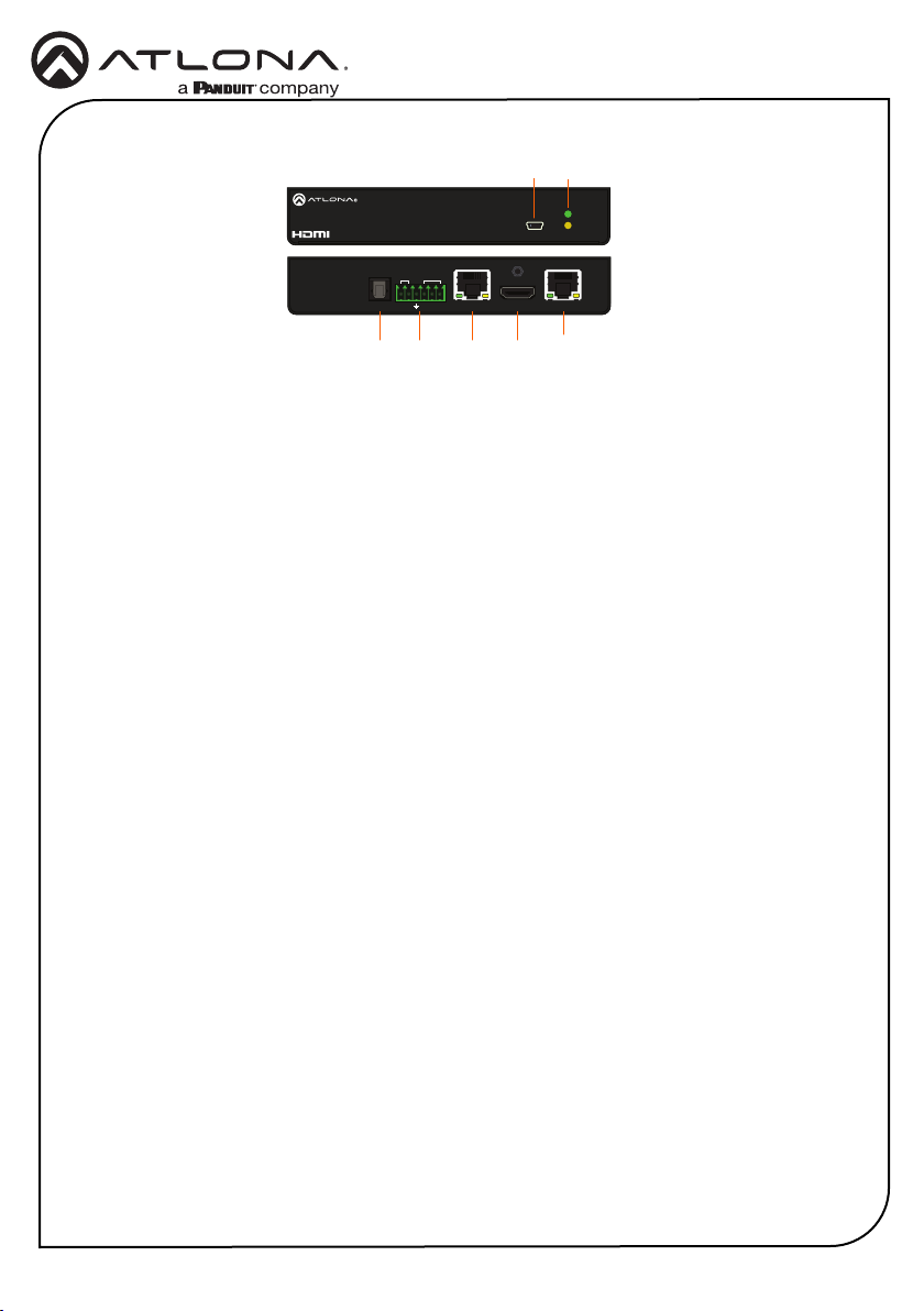
Panel Descriptions
OPTICAL
Installation Guide
AT-HDR-EX-100CEA-RX
21
AT-HDR-EX-100CEA-RX
POWER
FW
LINK
IN
IRRS-232
TX TX RXRX P
HDMI OUTHDBaseT IN
LAN
1 FW
Connect a mini-USB cable from this port
to update the rmware.
2 POWER and LINK LEDs
The power LED will illuminate green when
receiving power. The link LED will glow
yellow when signal is being sent/received
between the transmitter and the receiver.
3 OPTICAL IN
Not used at this time.
4 RS-232 / IR
Connect the included 6-pin captive screw
block to this receptacle.
4 5 6 7
5 HDBaseT IN
6 HDMI OUT
7 LAN
8
Connect an Ethernet cable from this port
to the HDBaseT OUT port on the AT-HDRCAT-4ED.
Connect an HDMI cable from this port to
an HDMI display.
Connect an Ethernet cable from this
port, on either the AT-HDR-CAT-4ED or
receiver, to the network or a display. Do
not connect both LAN ports to the same
network.
2
Page 3
Installation Guide
AT-HDR-EX-100CEA-RX
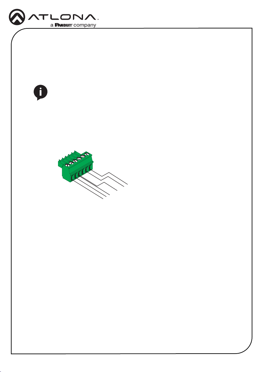
RS-232 / IR Wiring
The AT-HDR-EX-100CEA-RX provides both an RS-232 and IR port. RS-232 pass-through
is supported, allowing a control system to be connected to either the transmitter or receiver.
Connect the included IR emitter to the transmitter and an IR extender (not included) to the
receiver. Both IR and RS-232 connections are optional.
NOTE: Typical DB9 connectors use pin 2 for TX, pin 3 for RX, and pin 5 for
ground. On some devices functions of pins 2 and 3 are reversed. Also note, that
IR is bidirectional, allowing the IR emitter or IR receiver to be connected to either
the transmitter or receiver.
1. Use wire strippers to remove at least 3/16” (5 mm) of the cable jacket for both the RS-232
and IR emitter.
2. Insert the wires as shown into the included 6-pin captive screw connector.
P
RxD
TxD
GND
TxD
RxD
AT-HDR-EX-100CEA-RX
P
S
GND
GND
RxD
TxD
IR Receiver
Display
3
Page 4
Installation Guide
AT-HDR-EX-100CEA-RX
Mounting Instructions
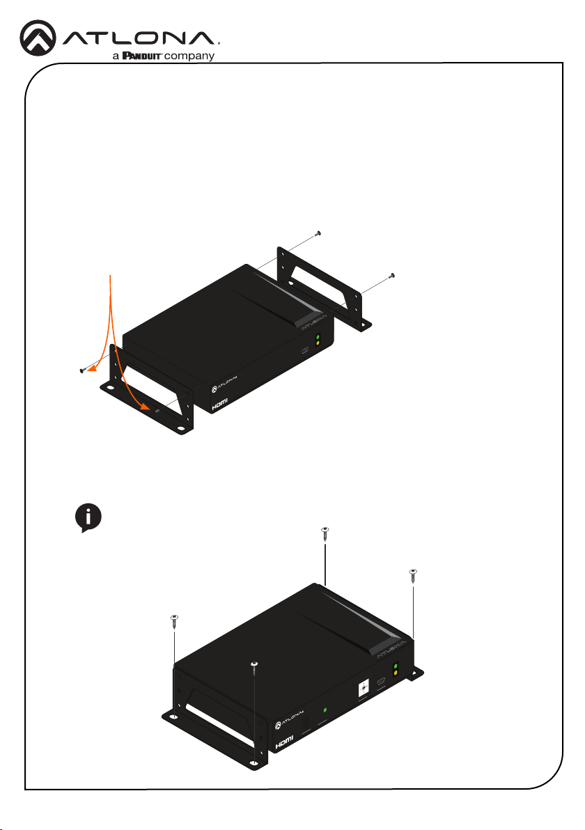
The AT-HDR-EX-100CEA-RX includes two mounting brackets and four mounting screws, which
can be used to attach the units to any at surface.
1. Position one of the mounting brackets, as shown below, aligning the holes on the side of the
enclosure with one set of holes on the mounting bracket.
2. Use the enclosure screws to secure the mounting bracket to the enclosure.
3. Repeat the above steps to attach the second mounting bracket to the opposite side of the
unit.
Included screws
AT-HDR-EX-100CEA-RX
POWER
LINK
FW
4. Mount the unit using the oval-shaped holes, on each mounting bracket. If using a drywall
surface, a #6 drywall screw is recommended.
NOTE: Mounting brackets can also be inverted to mount the unit under a table
or other at surface.
AT-HDR-EX-100CEA-TX
POWER
1. LINK
2. FW
3. TEST
4. 5V LOCK
LINKTEST
UTILITY
4
Page 5
Installation Guide
AT-HDR-EX-100CEA-RX
Installation
1. Connect an HDMI display to the HDMI OUT port on the receiver.
2. Connect an Ethernet cable from the LAN port, on either the transmitter or receiver, to the
Local Area Network.
3. *OPTIONAL* Connect a control system to the transmitter. Connect the device being
controlled to the receiver.
4. *OPTIONAL* Connect an IR receiver to the receiver.
5. Connect an Ethernet cable, from the HDBaseT OUT port on the AT-HDR-CAT-4ED, to the
HDBaseT IN port on the receiver.
6. Connect the power supply to an available AC outlet.
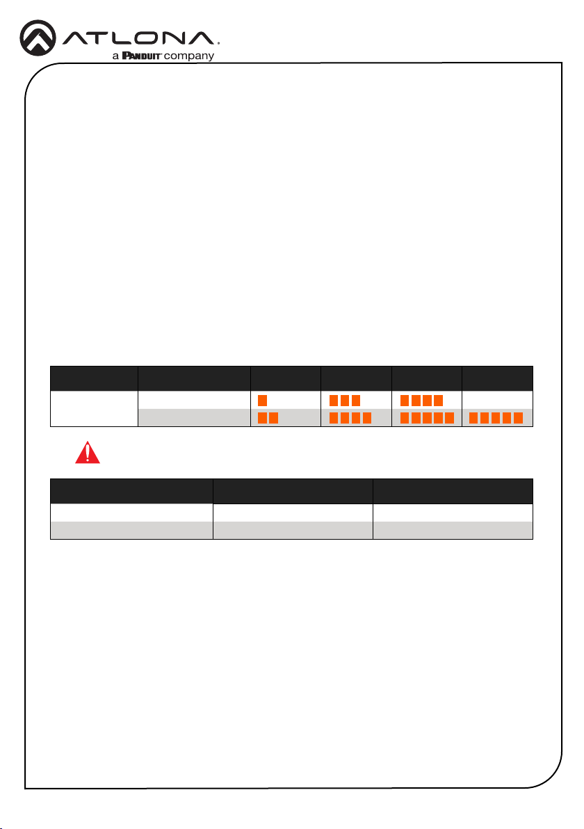
Cable Recommendation Guidelines
Refer to the tables below for recommended cabling when using Altona products with HDBaseT.
The green bars indicate the signal quality when using each type of cable. Higher-quality signals
are represented by more bars.
Core Shielding CAT5e CAT 6 CAT6a CAT 7
Solid UTP (unshielded) N/A
STP (shielded)
IMPORTANT: Stranded or patch cables are not recommended due to
performance issues.
Cable* Max. Distance @ 4K Max. Distance @ 1080p
CAT5e 295 feet (90 meters) 330 feet (100 meters)
CAT6 / CAT6a / CAT7 330 feet (100 meters) 330 feet (100 meters)
*Atlona recommends TIA/EIA 568-B termination for optimal performance.
5
Page 6
Installation Guide
AT-HDR-EX-100CEA-RX
Updating the Firmware
1. Download the rmware le from the Firmware tab located at https://atlona.com/at-hdr-ex-
100cea-rx.
2. Extract the rmware, from the archive le, to the Windows desktop or other folder.
3. Disconnect the Ethernet cable from the HDBaseT IN port on the receiver.
4. Connect a mini-USB to USB-A cable from the FW port on the receiver, to the computer with
the rmware le.
5. Reconnect the Ethernet cable to the HDBaseT IN port on the receiver. The USB Drive
folder should be displayed after a few seconds. If the folder is not displayed select the USB
drive from Windows Explorer.
4. Delete all les from the USB Drive folder, if any are present.
5. Drag and drop the rmware le to the drive. While the rmware loads to the unit, the green
power LED on the front panel will ash.
6. Once the LED is solid green, disconnect the unit from the computer.
The rmware update process is complete.
6
Page 7
Notes
Installation Guide
AT-HDR-EX-100CEA-RX
7
Page 8
Installation Guide
AT-HDR-EX-100CEA-RX
Warranty
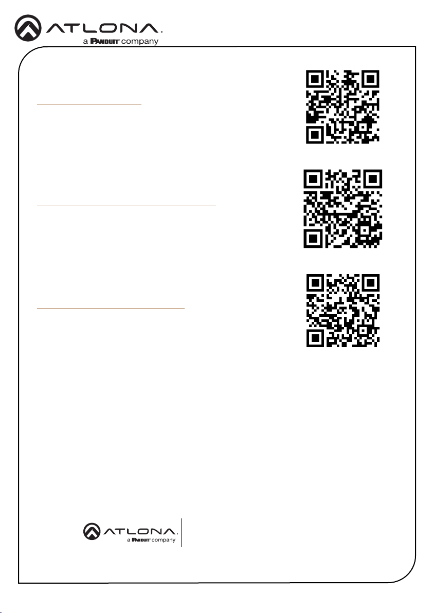
To view the product warranty, use the following link or QR code:
https://atlona.com/warranty/.
English Declaration of Conformity
The English version can be found under the resources tab at:
https://atlona.com/product/at-hdr-ex-100cea-rx/.
Chinese Declaration of Conformity 中国RoHS合格声明
由SKU列出於:
https://atlona.com/about-us/china-rohs/.
Version 1
atlona.com • 408.962.0515 • 41.43.508.4321
US International
© 2023 Atlona Inc. All rights reserved. “Atlona” and the Atlona logo are registered trademarks of Atlona Inc. All other brand names and trademarks or registered
trademarks are the property of their respective owners. Pricing, specications and availability subject to change without notice. Actual products, product images, and
online product images may vary from images shown here.
8
25320-R1
 Loading...