

Page 1
FROST TOP - WF SERIES
Service and Installation Manual
Please read this manual completely before attempting to install or operate this equipment!
Notify carrier of damage! Inspect all components immediately. See page 1.
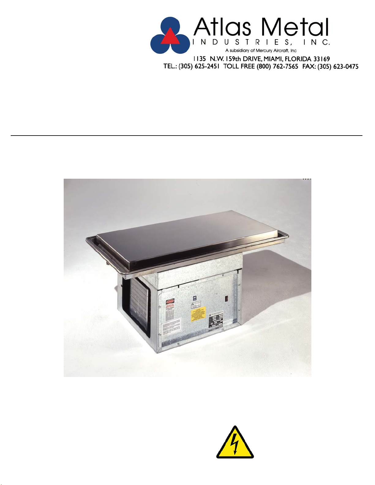
DROP-IN FROST TOP
REFRIGERATED, SELF-CONTAINED
OR REMOTE
Effective Date: 2011
IMPORTANT INFORMATION
READ BEFORE USE
Page 2

CONTENTS
RECEIVING & INSPECTING EQUIPMENT....................................................................................................................................................................................1
SERIAL AND MODEL # LOCATION..............................................................................................................................................................................................1
WF SPECIFICATIONS, FEATURES AND ACCESSORIES..........................................................................................................................................................2
ELECTRICAL CHARACTERISTICS AND CUT-OUT REQUIREMEMENTS AND REFRIGERATION CHART.................................................3
INSTALLATION, OPERATION AND S/S MAINTENANCE......................................................................................................................................4
IMPORTANT INFORMATION-PLEASE READ OPERATING INSTRUCTIION......................................................................................................................5
PARTS LIST..............................................................................................................................................................................................................................6
TROUBLE SHOOTING GUIDE.............................................................................................................................................................................................7
ELECTRICAL SCHEMATICS.................................................................................................................................................................................................8
LIMITED WARRANTY............................................................................................................................................................................................................9
WARRANTY INFORMATION..............................................................................................................................................................................................10
RECEIVING AND INSPECTING THE EQUIPMENT
1. VISUALLY INSPECT THE SHIPPING CRATE. DAMAGE SHOULD BE NOTED AND REPORTED TO THE DELIVERING CARRIER.
2. IF DAMAGED, OPEN AND INSPECT CONTENTS WITH CARRIER.
3. IF CRATE IS NOT DAMAGED AND THERE IS CONCEALED DAMAGE TO THE EQUIPMENT, NOTIFY THE CARRIER. NOTIFICATION MUST BE
MADE VERBALLY AND IN WRITING.
4. REQUEST AN INSPECTION BY THE SHIPPING COMPANY FOR THE DAMAGED EQUIPMENT WITHIN 10 DAYS FROM RECEIPT OF THE
EQUIPMENT
5. FREIGHT CARRIERS CAN SUPPLY THE NECESSARY FORMS ON REQUEST.
6. SAVE ALL CRATING MATERIALS UNTIL INSPECTION HAS BEEN MADE OR WAIVED.
SERIAL NUMBER LOCATION
THE SERIAL AND MODEL# CAN BE FOUND ON THE CONDENSING UNIT ENCLOSURE - SEE OPERATORS SIDE CONTROL PANEL WHEN
CALLING ATLAS FOR PARTS AND SERVICE. ALWAYS HAVE THIS INFORMATION AVAILABLE.
SERIAL #: _______________________________________________________
MODEL #:_______________________________________________________
INSTALLATION DATE: _____________________________________________
Page 3

Project: ___________
Item No.: ___________
Quantity: ___________
DROP-IN SERVING EQUIPMENT
WF-2
FROST TOP
Refrigerated,
Self-Contained
SPECIFICATIONS
TOP: Constructed of 14 gauge, type 304 stainless steel, die
stamped with a raised perimeter bead. There shall be a solid
vinyl gasket under the beaded edge to form a seal to the
counter top, thus preventing seepage or marring of the
counter top.
FROST TOP: Constructed of 14 gauge, type 304 stainless
steel, one piece construction, all welded, ground and polished to a uniform finish. The top is formed to stand 1" above
the counter top and is provided with a 1/2" full perimeter gutter to collect condensation; a 1" I.P.S. drain is provided. The
frost top has copper tubing firmly soldered to the exterior
bottom.
INSULATION: The pan is fully insulated with high density
fiberglass and polystyrene, 1-1/2" thick, and enclosed with
an 18 gauge galvanized steel outer case.
REFRIGERATION SYSTEM: The compressor housing shall
be fabricated from 14 gauge galvanized steel and bolted to
the base of the unit. A fully self-contained condensing unit is
provided with a hermetically sealed compressor. The system
is fully charged with CFC free refrigerant and ready to operate.
WF-3
WF-4
WF-5
WF-6
STANDARD FEATURES
“Quick” frost top, stands 1” above counter for attractive
display - ideal for pre-plated cold food
Fully insulated for maximum efficiency and energy
savings
Factory applied gasket - makes installation a snap and
seals units to the counter top, thus eliminating
seepage
1-Year Parts & Labor Warranty
NSF Certified and UL Recognized
ACCESSORIES
5YW - 5-Year Compressor Warranty
WFFT - Flush recessed top for frost top units
RS - Remote on/off switch for counter mounting
RDVE - Rear Drain Valve Extension
* 220 Volt - 50 Cycle Compressor
NOTE: Proper ventilation must be provided in counter.
ELECTRICAL: The unit will be wired for 15 amps., 120 volt,
single phase operation with an on/off switch and pilot light. A
6' long 3-wire cord and plug (NEMA 5-15P) will be provided.
Specifications subject to change without notice.
* Units with these accessories are not currently UL listed.
DI-37
Page 4
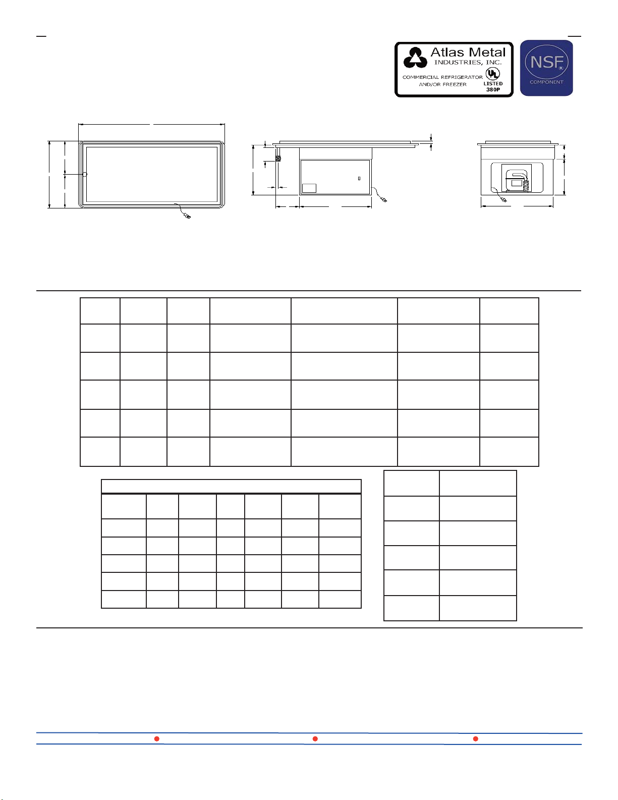
A
24”
12”
12”
PLAN VIEW
MODEL “A” “B”
WF-2
WF-3
WF-4
WF-5
WF-6
29-3/4”
(75.5cm)6”(15.2cm)
43-1/2”
(110.4cm)7”(17.7cm)
57-1/4”
(145.4cm)7”(17.7cm)
71”
(180.3cm)7”(17.7cm)
84-3/4”
(215.2cm)7”(17.7cm)
3”
18”
3/4”
FROST TOP
SIZE
19-1/2” X 25-1/4”
(49.5 X 64.1cm)
19-1/2” X 39”
(49.5 X 99cm)
19-1/2” X 52-3/4”
(49.5 X 133.9cm)
19-1/2” X 66-1/2”
(49.5 X 168.9cm)
19-1/2” X 80-1/4”
(49.5 X 203.8cm)
B
21-1/2”
ELEVATION
ELECTRICAL
CHARACTERISTICS
3.9amps. - 120V 1/5HP
6.8amps. - 120V 1/4HP
9.8amps. - 120V 1/3HP
9.8amps. - 120V 1/3HP
10.7amps. - 120V 1/2HP
1”
CUT-OUT
REQUIRED
22-1/4” X 28”
(56.5 X 71.1cm)
22-1/4” X 41-3/4”
(56.5 X 106cm)
22-1/4” X 55-1/2”
(56.5 X 140.9cm)
22-1/4” X 69-1/4”
(56.5 X 175.8cm)
22-1/4” X 83”
(56.5 X 210.8cm)
5”
13”
21-1/2”
END VIEW
SHIP WT.
(LBS.)
171
(77.6kg)
207
(93.9kg)
236
(107kg)
263
(119.3kg)
328
(148.8kg)
REFRIGERATION CHART
MODEL HP REF. OZ.
WF-2 1/5 134A 6 8 150 505
WF-3 1/4 134A 8 8 155 1070
WF-4 1/3 134A 10 8 155 1285
WF-5 1/3 134A 12 8 155 1285
WF-6 1/2 134A 16 8 160 2140
WFX - REFRIGERATED FROST TOP WITHOUT
LOW
PSIG.
HIGH
PSIG.
MODEL
BTU
M10 90A
WFX-2
WFX-3
WFX-4
WFX-5
WFX-6
COMPRESSORS FOR REMOTE INSTALLATIONS
WT. LESS
COMP. (LBS.)
130
(59kg)
160
(72.6kg)
190
(86.2kg)
217
(98.4kg)
252
(114.3kg)
COMPRESSOR
Units include Refrigerated Frost Top,
Cap Tube & Drier (for hook up in field by others)
2029 - 1/5 HP for WFX-2
2029-1 - 1/4 HP for WFX-3
2029-2 - 1/3 HP for WFX-4 & 5
2001-4 - 1/2 HP for WFX-6
Atlas Metal Industries 1135 NW 159th Dr. Miami, Fl 33169 (800) 762-7565 Fax: (305) 623-0475 atlasfoodserv.com
DI-38
8/13-sc
Page 5

FROST TOP
WF SERIES
----------------------------------------------------------------------------------------------------------------------------------------------------------
INSTALLATION
Provide the correct counter cut-out opening (see chart below) and drop in. The vinyl gasket assures complete
seating. A non-toxic silicone seal may be used between the gasket and counter top (not required).
Note: Units are supplied with a nipple and gate valve to be connected for draining.
MODEL NUMBER CUT-OUT SIZE
WF-2 22 1/4 X 28
WF-3 22 1/4 X 41 3/4
WF-4 22 1/4 X 55 1/2
WF-5 22 1/4 X 69 1/4
WF-6 22 1/4 X 83
The unit should be level for draining purposes. When installing unit in a counter, it is recommended that the
operator side of the counter be completely open for air circulation. When this is not possible, such as in an
island counter, it is recommended that two grill openings are provided approximately 18” x 18” of free air for
intake and exhaust at the opposite ends of the counter.
The unit is supplied with a power cord and NEMA plug. Refer to the data plate on the compressor housing for
the amperage and voltage information. Use a licensed electrician when installing power source.
---------------------------------------------------------------------------------------------------------------------------------------------------------------
OPERATION
This unit should be turned on one hour before serving and turned off after completing the serving period.
There is an on/off switch located on the compressor housing. It may take a while for the frost to cover the
entire surface (depending on the humidity). The compressor runs continuously to maintain a layer of frost.
The unit should not operate 24/7.
---------------------------------------------------------------------------------------------------------------------------------------------------------------
MAINTENANCE
NEVER CLEAN PANS WITH A CHLORIDE BASED PRODUCT. CHLORIDES OR IMPROPER
CLEANING COULD SCAR, MARK AND/OR CORRODE SURFACE. DO NOT USE STEEL WOOL OR
ABRASIVE PRODUCTS. TO CLEAN USE SOAPY WARM WATER, RINSE THOROUGHLY TO
REMOVE ALL RESIDUES. FAILURE TO MEET THESE CONDITIONS WILL VOID WARRANTY.
CLEAN CONDENSER COIL REGULARLY.
Page 6

IMPORTANT INFORMATION PLEASE READ
WF-SERIES
FROST TOP OPERATING INSTRUCTIONS
The unit requires proper ventilation for the refrigeration system, which must be provided for
during installation. The compressor unit required regular cleaning to keep the unit free of
dust and dirt building up on the condenser coils.
This unit must be placed in an environment with minimal air flow over the stainless steel
surface plate. Air currents directly over the frost plate created by ceiling fans, air
conditioning vents, doorways and the alike, will prevent the unit from frosting properly.
Check first for air currents in the room if frost patterns are not optimal.
This WF unit has been inspected at room temperature for frost plate flatness. During the
refrigeration/frosting process, the stainless surface can contrast and bow. If there is a layer of
frost across the surface area of the plate, the WF unit is operating to specification and does
not require service.
The factory must be contacted to receive authorization to perform in-field service on the WF
unit. This must be done prior to the work being done. If service is requested, the factory will
ask you to confirm that the checks for air circulation and frost patterns on the stainless plate
have been conducted. If the service agency finds the unit to be deficient, the factory will
assume responsibility for the cost of the repair. If the factory determines that the WF unit is
within the established dimensional and performance standards, the service agency will be
instructed to bill you directly.
Page 7

Subsidiary of Mercury Aircraft, Inc.
1135 N.W. 159th DR., MIAMI, FL 33169
PHONE (305) 625-2451, (800) 762-7565, FAX (305) 623-0475, E-mail: sales@atlasfoodserv.com
PARTS LIST FROST TOP
WF SERIES
1
2
3
6
WF-4 SHOWN
ITEM NUMBER PART NUMBER DESCRIPTION
1 7002-0+Model # Vinyl Bead Gasket (Not Shown)
2 1012-02902 3/4" x 4 PVC Nipple
3 1012-0906 Ball Valve
4 1003-0 Power Cord with Plug.
5 1069-1 14 Amps. Toggle Switch
2029-0 1/5 H.P. Compressor (WF-2).
6
7 2027-0 0.031 Cap Tube for 1/5 Compressor Only. (Not Shown)
8
9 2025-0 Drier
2029-1 1/4 H.P. Compressor (WF-3).
2029-2 1/3 H.P. Compressor (WF-4 & 5).
2001-4 1/2 H.P. Compressor (WF-6).
2026-0 0.042 Cap Tube for 1/4, 1/3 & 1/2 Compressor. (Not Shown)
4
5
Page 8

Page 9

Page 10

LIMITED WARRANTY
Atlas Metal Industries, Inc. warrants to the Purchaser of this product that the
same shall be free from defects in the workmanship and material for a period of
one year from the date of original installation of the equipment, but not to exceed
eighteen (18) months after date of shipment from factory. During this period of
time Atlas Metal Industries, Inc. will replace all defective parts and will pay for
authorized replacement labor. Replacement and installation of such parts and
labor shall be provided only upon prior written authority of Atlas Metal Industries,
Inc.
The Refrigeration warranty is for a twenty (20) month time period and includes
supplying the compressor at a no charge basis provided the damage to the
compressor was not caused by the customer or end user. Authorized
replacement labor will be paid for a period of one year from date of installation.
Freight costs for defective unit to and from Atlas Metal Industries, Inc. are not
included, and all defective parts must be returned to the factory freight prepaid
for evaluation. ALL WARRANTY LABOR MUST BE AUTHORIZED BY ATLAS
METAL INDUSTRIES, INC. PRIOR TO THE ACTUAL WORK BEING DONE.
This warranty does not apply to any equipment or any part thereof, which has
been subjected to shipping damage, improper voltage, alteration, abuse or
misuses, and does not cover loss of food, other products, or damage to property
due to mechanical or electrical malfunction.
THERE ARE NO WARRANTIES WHICH EXTEND BEYOND THE
DESCRIPTION OF THE FACE HEREOF. SELLER DISCLAIMS ANY IMPLIED
WARRANTY OF MERCHANTABILITY OF THE GOODS OR THE FITNESS OF
THE GOODS FOR ANY PURPOSE AND BUYER AGREES THAT THE GOODS
ARE SOLD “AS IS.”
Page 11

WARRANTY INFORMATION
In order to have your invoice approved for payment by the factory, please note the following:
_______________________________________________
An authorization number must be obtained from the factory prior to performing any warranty service.
_______________________________________________
Atlas Metal
will not approve excessive labor due to poor
access to the unit being serviced. If design does
not
allow reasonable access, contact the factory.
_______________________________________________
All travel time that exceeds 100 miles round trip must be authorized by the factory.
_____________________________________________________________________________________
Thank You:
Warranty service Dept.
 Loading...