

Page 1
WCM/WCMD/WCMDC/WCML/WCMDL/WCMDCL
& WCMHP SERIES
Service and Installation Manual
Please read this manual completely before attempting to install or operate this equipment!
Notify carrier of damage! Inspect all components immediately. See page 1.
DROP-IN COLD PAN
REFRIGERATED STANDARD DEPTH,
FULL DEPTH, SIDE COILS & SLIM-LINE
SELF CONTAINED OR REMOTE
DROP-IN HOT/COLD PAN
DUAL SERVICE HOT OR COLD
(HOT MODE-WATER MUST BE USED)
Effective Date: 2011
IMPORTANT INFORMATION
READ BEFORE USE
Page 2

CONTENTS
RECEIVING & INSPECTING EQUIPMENT....................................................................................................................................................................................1
SERIAL AND MODEL # LOCATION..............................................................................................................................................................................................1
WCM SPECIFICATIONS, FEATURES ACCESSORIES................................................................................................................................................................2
ELECTRICAL CHARACTERISTICS AND CUT-OUT REQUIREMEMENTS............................................................................................................3
INSTALLATION, OPERATION AND S/S MAINTENANCE......................................................................................................................................4
PARTS LIST.........................................................................................................................................................................................................................5
WCM-HP SPECIFICATIONS FEATURES AND ACCESSORIES................................................................................................................................................6
ELECTRICAL CHARACTERISTICS AND CUT-OUT REQUIRMENTS.....................................................................................................................7
INSTALLATION, OPERATION AND S/S MAINTENANCE.......................................................................................................................................8
PARTS LIST..........................................................................................................................................................................................................................9
AUTOMATIC WATER FILL INSTALLATION, OPERATION & PARTS LIST............................................................................................................................10
TROUBLE SHOOTING GUIDE.........................................................................................................................................................................................................11
ELECTRICAL & REFRIGERATION CHART.....................................................................................................................................................................................12
ELECTRICAL SCHEMATICS..................................................................................................................................................................................................13,14,15
LIMITED WARRANTY.........................................................................................................................................................................................................................16
WARRANTY INFORMATION............................................................................................................................................................................................................17
RECEIVING AND INSPECTING THE EQUIPMENT
1. VISUALLY INSPECT THE SHIPPING CRATE. DAMAGE SHOULD BE NOTED AND REPORTED TO THE DELIVERING CARRIER.
2. IF DAMAGED, OPEN AND INSPECT CONTENTS WITH CARRIER.
3. IF CRATE IS NOT DAMAGED AND THERE IS CONCEALED DAMAGE TO THE EQUIPMENT, NOTIFY THE CARRIER. NOTIFICATION MUST BE
MADE VERBALLY AND IN WRITING.
4. REQUEST AN INSPECTION BY THE SHIPPING COMPANY FOR THE DAMAGED EQUIPMENT WITHIN 10 DAYS FROM RECEIPT OF THE
EQUIPMENT
5. FREIGHT CARRIERS CAN SUPPLY THE NECESSARY FORMS ON REQUEST.
6. SAVE ALL CRATING MATERIALS UNTIL INSPECTION HAS BEEN MADE OR WAIVED.
RECEIVING AND INSPECTING THE EQUIPMENT
THE SERIAL AND MODEL# CAN BE FOUND ON THE CONDENSING UNIT ENCLOSURE - SEE OPERATORS SIDE CONTROL PANEL WHEN
CALLING ATLAS FOR PARTS AND SERVICE. ALWAYS HAVE THIS INFORMATION AVAILABLE.
SERIAL #: _______________________________________________________
MODEL #:_______________________________________________________
INSTALLATION DATE: _____________________________________________
1
Page 3
Project: ___________
Item No.: ___________
Quantity: ___________
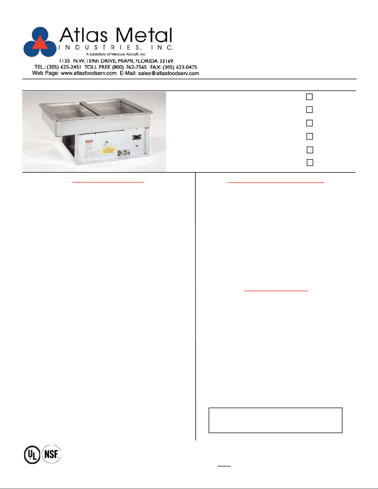
DROP-IN SERVING EQUIPMENT
WCM-1
COLD PAN
Refrigerated
4-5/8” Standard Depth
Self-Contained
WCM-2
SPECIFICATIONS
TOP: Constructed of 18 gauge, type 304 stainless steel, die
stamped with a raised perimeter bead. There shall be a solid
vinyl gasket under the beaded edge to form a seal to the
counter top, thus preventing seepage or marring of the
counter top. Embossed mounting lugs are provided along the
inner surface of the top to hold the removable separator
channels in place.
LINER: The inner liner shall be 18 gauge, type 304 stainless
steel, one piece construction, all welded, ground and polished to a uniform finish. All corners are coved with a minimum 1/4" radius. The liner has copper tubing firmly soldered
to the exterior bottom. A 3/4" dia. drain with strainer, 4" PVC
nipple, and valve is provided.
WCM-2
WCM-3
WCM-4
WCM-5
WCM-6
STANDARD FEATURES
Fully insulated for maximum efficiency and energy
savings
Factory applied gasket - makes installation a snap and
seals units to the counter top, thus eliminating
seepage
Accommodates standard 12” X 20” pans with the use
of separator channel(s), or fractional size pans with
the use of optional adapter bars
1-Year Parts & Labor Warranty
NSF Certified; UL Recognized
ACCESSORIES
INSULATION: The pan is fully insulated with high density
polystyrene, 1" thick on all sides, 1-1/2" thick on the bottom
and enclosed with a 22 gauge galvanized steel outer case.
REFRIGERATION SYSTEM: The compressor housing shall
be fabricated from 14 gauge galvanized and bolted to the
base of the unit. A fully self-contained condensing unit is provided with a hermetically sealed compressor and a thermostat control. The system is fully charged with CFC free
refrigerant and ready to operate.
NOTE: Proper ventilation must be provided in counter.
ELECTRICAL: The unit will be wired for 15 amps., 120 volt,
single phase, with an on/off thermostat switch and pilot light.
A 6' long, 3-wire cord and plug (NEMA 5-15P) will be provided.
Specifications subject to change without notice.
* Units with these accessories are not currently UL listed.
5YW - 5-Year Compressor Warranty
WFB - Stainless steel perforated false bottom
Stainless Steel adapter bars (pg DI-51-52)
Stainless Steel adapter plates (pg DI-51-52)
CP - Cover Plate with handles, S/S
2060-1 - Condensate Evaporator
RS - Remote on/off switch for counter mounting
* RDVE - Rear Drain Valve Extension
* 220 Volt - 50 Cycle Compressor
These units have not been performance
tested for use with potentially hazardous foods,
and must be used with ice.
DI-23
2
Page 4
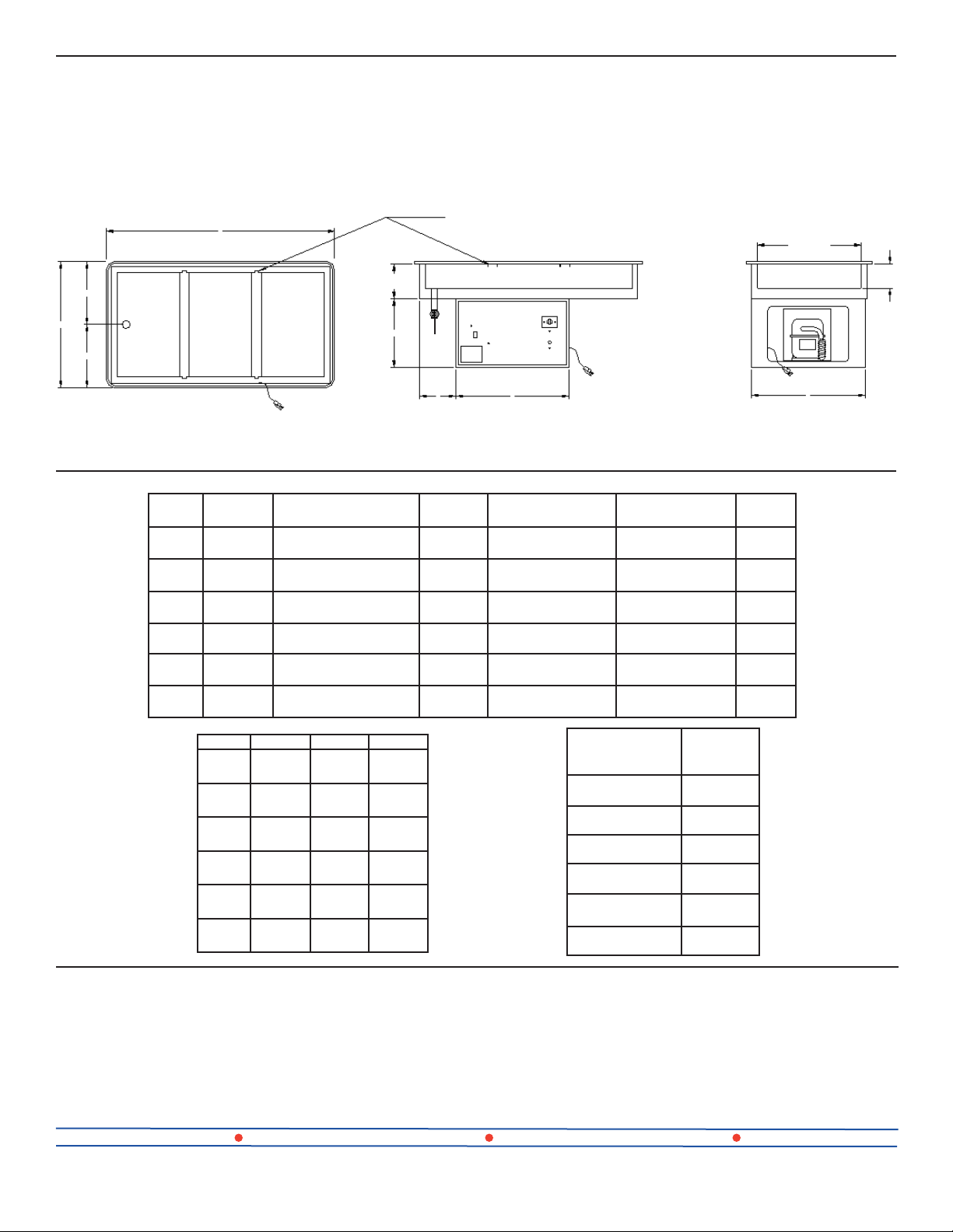
REMOVABLE SEPARATOR
A
CHANNEL
19-7/8”
24”
12”
12”
PLAN VIEW
*Drain Location on 16” Dimension
MODEL
*WCM-1 1
WCM-2 2
WCM-3 3
WCM-4 4
WCM-5 5
WCM-6 6
PAN
OPENINGS
PAN SIZE “A”
19-7/8” X 11-3/4” X 4-5/8”
(50.4 X 29.8 X 11.7cm)
19-7/8” X 25-1/2” X 4-5/8”
(50.4 X 64.7 X 11.7cm)
19-7/8” X 39-1/4” X 4-5/8”
(50.4 X 99.6 X 11.7cm)
19-7/8” X 53” X 4-5/8”
(50.4 X 134.6 X 11.7cm)
19-7/8” X 66-3/4” X 4-5/8”
(50.4 X 169.5 X 11.7cm)
19-7/8” X 80-1/2” X 4-5/8”
(50.4 X 204.4 X 11.7cm)
6-5/8”
13”
2-3/4”
B
16”
(40.6cm)
29-3/4”
(75.2cm)
43-1/2”
(110.4cm)
57-1/4”
(145.4cm)
71”
(180.3cm)
84-3/4”
(215.2cm)
C
ELEVATION
ELECTRICAL
CHARACTERISTICS
2.4 amps. - 120V -
3.9 amps. - 120V -
3.9 amps. - 120V -
6.8 amps. - 120V -
9.8 amps. - 120V -
9.8 amps. - 120V -
1/5HP
1/5HP
1/5HP
1/4HP
1/3HP
1/3HP
CUT-OUT
REQUIRED
22-1/4” X 14-1/4”
(56.5 X 36.1cm)
22-1/4” X 28”
(56.5 X 71.1cm)
22-1/4” X 41-3/4”
(56.5 X 106cm)
22-1/4” X 55-1/2”
(56.5 X 140.9cm)
22-1/4” X 69-1/4”
(56.5 X 175.8cm)
22-1/4” X 83”
(56.5 X 210.8cm)
4-5/8”
D
END VIEW
SHIP WT.
(LBS.)
116
(52.6kg)
164
(74.4kg)
198
(89.8kg)
226
(102.5kg)
262
(118.8kg)
316
(143.3kg)
B C D
WCM-1
WCM-2
WCM-3
WCM-4
WCM-5
WCM-6
3-7/8”
(9.8cm)
5-5/8”
(15.2cm)
7”
(17.7cm)
7”
(17.7cm)
7”
(17.7cm)
7”
(17.7cm)
18”
(45.7cm)
21-1/2”
(54.6cm)
21-1/2”
(54.6cm)
21-1/2”
(54.6cm)
21-1/2”
(54.6cm)
21-1/2”
(54.6cm)
13-3/4”
(34.9cm)
21-5/8”
(54.9cm)
21-5/8”
(54.9cm)
21-5/8”
(54.9cm)
21-5/8”
(54.9cm)
21-5/8”
(54.9cm)
WCMX - REFRIGERATED COLD PAN WITHOUT
REMOTE
REFRIGERATION
MODEL
WCMX-1
WCMX-2
WCMX-3
WCMX-4
WCMX-5
WCMX-6
COMPRESSORS FOR REMOTE INSTALLATIONS
LESS COMP.
SHIP WT.
(LBS.)
74
(33.5kg)
120
(54.4kg)
153
(69.3kg)
168
(76.2kg)
209
(94.8kg)
264
(119.7kg)
COMPRESSOR
Units include Refrigerated Cold Pan,
Thermostat, Cap Tube & Drier (for hook up in field
by others)
Atlas Metal Industries 1135 NW 159th Dr. Miami, FL 33169 (800) 762-7565 Fax: (305) 623-0475 atlasfoodserv.com
2029 - 1/5 HP for WCMX-1, 2, & 3
2029-1 - 1/4 HP for WCMX-4
2029-2 - 1/3 HP for WCMX-5 & 6
DI-24
02/11-sc
3
Page 5

MECHANICAL COLD PANS
WCM/WCMD/WCMDC/WCML/WCMDL & WCMDCL SERIES
-----------------------------------------------------------------------------------------------------------------------------------------------------------------------
INSTALLATION
Provide the correct counter cut-out opening (see chart below) and drop in. The vinyl gasket assures complete
seating. A non-toxic silicone seal may be used between the gasket and counter top (not required).
Note: Units are supplied with a nipple and stop valve to be connected for draining.
MODEL NUMBER
WCM/ WCMD & WCMDC-1 22 1/4 X 14 1/4
WCM/ WCMD & WCMDC-2 22 1/4 X 28
WCM/ WCMD & WCMDC-3 22 1/4 X 41 3/4
WCM/ WCMD & WCMDC-4 22 1/4 X 55 1/2
WCM/ WCMD & WCMDC-5 22 1/4 X 69 1/4
WCM/ WCMD & WCMDC-6 22 1/4 X 83
WCML/ WCMDL & WCMDCL-2 14 1/4 X 44 1/4
WCML/ WCMDL & WCMDCL-3 14 1/4 X 66
WCML/ WCMDL & WCMDCL-4 14 1/4 X 87 3/4
------------------------------------------------------------------------------------------------------------------------------------------The unit should be level for draining purposes. When installing unit in a counter, it is recommended that the
operator side of the counter be completely open for air circulation. When this is not possible, such as in an island
counter, it is recommended that two grill openings are provided approximately 18” x 18” of free air for intake and
exhaust at the opposite ends of the counter.
The unit is supplied with a power cord and NEMA plug. Refer to the data plate on the compressor housing for the
amperage and voltage information. Use a licensed electrician when installing power source.
-----------------------------------------------------------------------------------------------------------------------------------------------------------------------
CUT-OUT SIZE
OPERATION
This unit should be turned on one hour before serving and turned off after completing the serving period. The
thermostat has an off position and numbers from 1 through 7, (number 7 is the coldest). Note: The unit should not
operate 24/7.
----------------------------------------------------------------------------------------------------------------------------------------------------------------------
MAINTENANCE
NEVER CLEAN PANS WITH A CHLORIDE BASED PRODUCT. CHLORIDES OR IMPROPER CLEANING
COULD SCAR, MARK AND/OR CORRODE PANS. DO NOT USE STEEL WOOL OR ABRASIVE
PRODUCTS. TO CLEAN USE SOAPY WARM WATER, RINSE THOROUGHLY TO REMOVE ALL
RESIDUES. FAILURE TO MEET THESE CONDITIONS WILL VOID WARRANTY.
CLEAN CONDENSER COIL REGULARLY.
4
Page 6
Subsidiary of Mercury Aircraft, Inc.
R
1135 N.W. 159th DR., MIAMI, FL 33169
PHONE (305) 625-2451, (800) 762-7565, FAX (305) 623-0475, E-mail: sales@atlasfoodserv.com
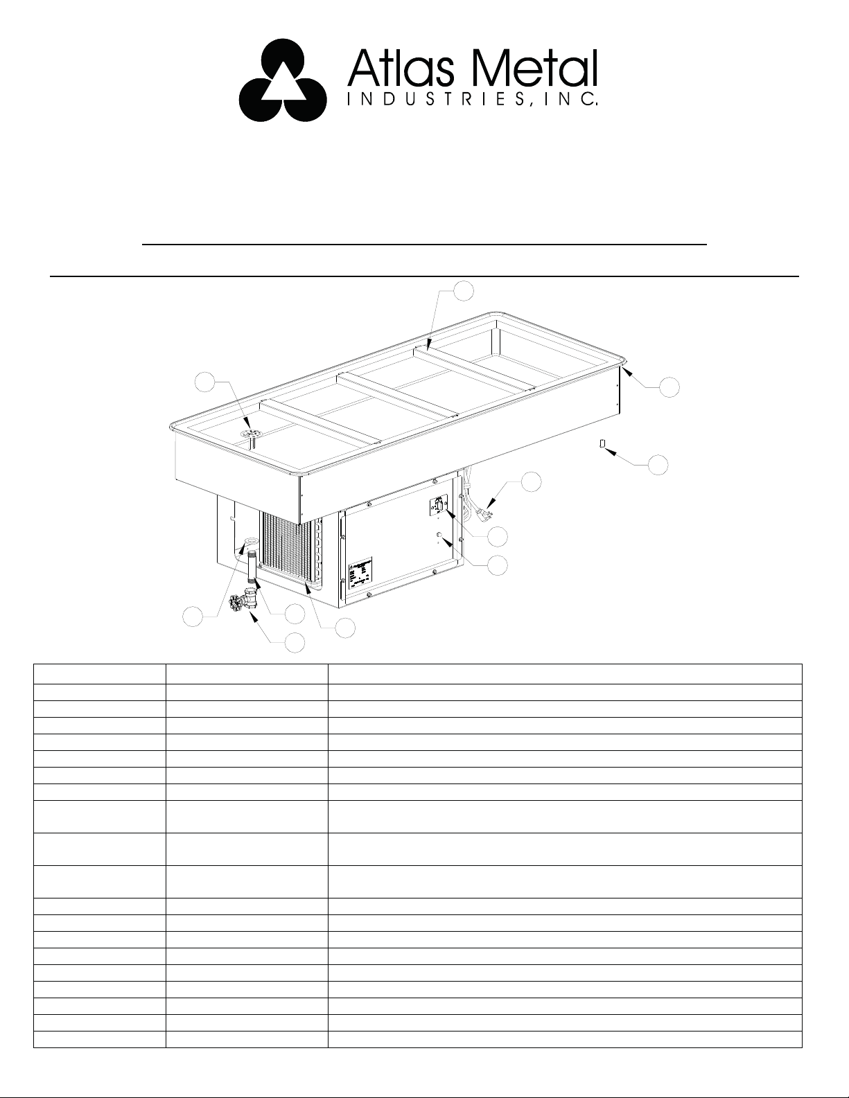
PARTS LIST FOR MECHANICAL COLD PANS
WCM/WCMD/WCMDC/WCML/WCMDL & WCMDCL SERIES
1
ITEM NUMBE
1 S80103-0 Separator Channel (WCM & WCMD)
1 S85008-0 Separator Channel (WCML & WCMDL)
2 86-3202 Perforated Snap- In Drain
3 7020-0 Nylon Spacer
4 7002-0+Model # Vinyl Bead Gasket
5 2044-0 Thermostat
6 1099-0 Pilot Light
7 2029-0 1/5 H.P. Compressor
7 2029-1 1/4 H.P. Compressor
7 2029-2 1/3 H.P. Compressor
8 49-1028 Grommet
9 30-3130 3/4 “ x 4” PVC Nipple
10 3016-2 Stop Valve
11 7041-0 Power Cord Bushing (Not Shown)
12 1003-0 Power Cord
13 2025 Drier (Not Shown)
14 2026 0.042 Cap Tube for 1/4, 1/3 & 1/2 Compressor (Not Shown)
15 2027 0.031 Cap Tube for 1/5 Compressor only (Not Shown)
16 600008 Thermostat Knob
2
12
5
6
10
9
7
WCM-4 SHOWN
8
PART NUMBER DESCRIPTION
(WCM-WCMD-WCMDC-1-2-3-WCML-WCMDL-WCMDCL-2-3)
(WCM-WCMD-WCMDC-WCMDL-WCMDCL-4)
(WCM-WCMD-WCMDC-5-6)
4
3
5
Page 7

Project: ___________
Item No.: ___________
Quantity: ___________
DROP-IN SERVING EQUIPMENT
HOT/COLD PAN
Dual Temp.
Hot or Cold Service
(For Hot Mode)
Water Must Be Used
WCM-HP-3
SPECIFICATIONS
TOP: Constructed of 18 gauge, type 304 stainless steel, die
stamped with a raised perimeter bead. There shall be a solid vinyl
gasket under the beaded edge to form a seal to the counter top,
thus preventing seepage or marring of the counter top. Embossed
mounting lugs are provided along the inner surface of the top to hold
a full set of removable separator channels in place.
LINER: The inner liner shall be 18 gauge, type 304 stainless steel,
one piece construction, all welded, ground and polished to a uniform
finish. All corners are coved with a minimum 1/4" radius. The liner
has copper tubing firmly soldered to the exterior sides. A 3/4" dia.
drain with strainer, 4” brass nipple, and valve is provided.
INSULATION: The pan is fully insulated with high density fiberglass,
1-3/8" thick on all sides, 1-1/2" thick on the bottom and enclosed
with a 22 gauge galvanized steel outer case.
HEATING ELEMENT: An immersion type heating element is provided in the bottom of the pan along with a perforated stainless steel
sheath cover. A thermostat control is included. Please note: the
element must
REFRIGERATION SYSTEM: The compressor housing shall be fab-
ricated from 14 gauge galvanized angles and bolted to the base of
the unit. A fully self-contained condensing unit is provided with a hermetically sealed compressor and a thermostat control. The system is
fully charged with CFC free refrigerant and ready to operate.
be submerged in water to operate properly.
WCM-HP-2
WCM-HP-3
WCM-HP-4
WCM-HP-5
WCM-HP-6
STANDARD FEATURES
Dual Temp. - a hot serving unit becomes a refrigerated cold
pan at the flip of a switch
Fully insulated for energy savings
Factory applied gasket - makes installation a snap and seals
units to the counter top, thus eliminating seepage
Accommodates standard 12” X 20” pans with the use of
separator channel(s), or fractional size pans with the use of
optional adapter bars.
1-Year Parts & Labor Warranty
NSF Certified; ULRecognized
ACCESSORIES
5YW - 5-Year Compressor Warranty
Stainless Steel adapter bars (pg DI-51-52)
Stainless Steel adapter plates (pg DI-51-52)
CP - Cover Plate with handles, S/S
RSHP - Remote Switch for counter mounting
* RDVE - Rear Drain Valve Extension
AF - Automatic water fill
* 220 Volt - 50 Cycle Compressor
NOTE: Proper ventilation must be provided in counter.
ELECTRICAL: The unit is pre-wired with a hot/cold selector switch
that prevents dual operation, with the required thermostat controls
and pilot light. The unit is provided with a 6’ long, 3-wire cord and a
twist lock plug.
Specifications subject to change without notice.
* Units with these accessories are not currently UL listed.
6
DI-35
Page 8

A
19-7/8”
12”
11”
24”
12”
13”
2-3/4”
B
PLAN VIEW
MODEL “A” PAN SIZE
WCM-HP-2
WCM-HP-3
WCM-HP-4
WCM-HP-5
WCM-HP-6
* Units are wired to prevent simultaneous operation in the hot and cold mode. Numeral following the model letters denotes the
12” x 20” pan capacity.
29-3/4”
(75.5cm)
43-1/2”
(110.4cm)
57-1/4”
(145.4cm)
(180.3cm)
84-3/4”
(215.2cm)
19-7/8” X 25-1/2” X 9-1/2”
(50.4 X 64.7 X 24.1cm)
19-7/8” X 39-1/4” X 9-1/2”
(50.4 X 99.6 X 24.1cm)
19-7/8” X 53” X 9-1/2”
(50.4 X 134.6 X 24.1cm)
71”
19-7/8” X 66-3/4” X 9-1/2”
(50.4 X 169.5 X 24.1cm)
19-7/8” X 80-1/2” X 9-1/2”
(50.4 X 204.4 X 24.1cm)
16.7 amps. - 2KW - 120V 2.4 amps. - 120V - 1/5 HP L5-30P
16.7 amps. - 2KW - 120V 2.4 amps. - 120V - 1/5 HP L5-30P
14.4 amps. - 3KW - 208V
12.5 amps. - 3KW - 240V
19.3 amps. - 4KW - 208V
16.7 amps. - 4KW - 240V
19.3 amps. - 4KW - 208V
16.7 amps. - 4KW - 240V
COUNTER
CUT-OUT REQUIRED
23-1/4” X 28-3/4”
2
(59 X 73cm)
23-1/4” X 42-1/2”
3
(59 X 107.9cm)
23-1/4” X 56-1/4”
4
(59 X 142.8cm)
23-1/4” X 70”
5
(59 X 177.8cm)
23-1/4” X 83-3/4”
6
(59 X 212.7cm)
WCM-HP-2
WCM-HP-3
WCM-HP-4
WCM-HP-5
WCM-HP-6
ELECTRICAL CHARACTERISTICS
HOT OPERATION COLD OPERATION
B C
4-3/8”
(11cm)
6-1/2”
(16.5cm)
6-1/2”
(16.5cm)
6-1/2”
(16.5cm)
6-1/2”
(16.5cm)
C
ELEVATION
7.5 amps. - 120V - 1/4 HP
7.5 amps. - 120V - 1/4 HP
9.8 amps. - 120V - 1/3 HP
9.8 amps. - 120V - 1/3 HP
9.8 amps. - 120V - 1/3 HP
9.8 amps. - 120V - 1/3 HP
REFRIGERATION
14”
(35.5cm)
21-1/2”
(54.6cm)
21-1/2”
(54.6cm)
21-1/2”
(54.6cm)
21-1/2”
(54.6cm)
NEMA
CONFIGURA-
TION
L14-30P
L14-30P
L14-30P
L14-30P
L14-30P
L14-30P
REMOTE
MODEL
WCM-HPX-2
WCM-HPX-3
WCM-HPX-4
WCM-HPX-5
WCM-HPX-6
9-1/2”
21-1/2”
END VIEW
SHIP WT.
(LBS.)
189
(85.7kg)
219
(99.3kg)
255
(115.7kg)
268
(121.6kg)
336
(152.4kg)
LESS COMP.
SHIP WT.
(LBS.)
148
(67.1kg)
178
(80.7kg)
208
(94.3kg)
222
(100.7kg)
290
(131.5kg)
WCM-HPX - HOT/COLD PAN WITHOUT
COMPRESSORS FOR REMOTE INSTALLATIONS
COMPRESSOR
Units include Hot/Cold Pan,
Thermostat, Cap Tube & Drier (for hook up in
field by others)
2029 - 1/5 HP for WCM-HPX-2, & 3
2029-1 - 1/4 HP for WCM-HPX-4
2029-2 - 1/3 HP for WCM-HPX-5 & 6
RSHP - Remote Control Panel is required to operate unit.
Atlas Metal Industries 1135 NW 159th Dr. Miami, FL 33169 (800) 762-7565 Fax: (305) 623-0475 atlasfoodserv.com
DI-36
7
02/11-sc
Page 9

HOT OR REFRIGERATED COLD PAN
WCM-HP SERIES
----------------------------------------------------------------------------------------------------------------------------------------------------------------------------
INSTALLATION
Provide the correct counter cut-out opening (see chart below, a 1” radius is required for each corner) and drop in. The
vinyl gasket assures complete seating. A non-toxic silicone seal may be used between the gasket and counter top (not
required).
Note: Units are supplied with a nipple and stop valve to be connected for draining.
MODEL
WCM-HP-2 23 1/4 X 28 3/4
WCM-HP-3 23 1/4 X 42 1/2
WCM-HP-4 23 1/4 X 56 1/4
WCM-HP-5 23 1/4 X 70
WCM-HP-6 23 1/4 X 83 3/4
CUT-OUT SIZE
The unit should be level for draining purposes. When installing unit in a counter, it is recommended that the operator
side of the counter be completely open for air circulation. When this is not possible, such as in an island counter, it is
recommended that two grill openings are provided, approximately 18” x 18” of free air for intake and exhaust, at the
opposite ends of the counter.
The unit is supplied with a power cord and NEMA plug. Refer to the data plate on the compressor housing for the
amperage and voltage information. Use a licensed electrician when installing power source.
“Waste water connections are to conform to the International Plumbing Code 2003, International Code Council (ICC) or
the Uniform Plumbing Code 2003, International Association of Plumbing and Mechanical Officials (IAPMO)” or
the equivalent.
----------------------------------------------------------------------------------------------------------------------------------------------------------------------------
OPERATION
HEATING CYCLE HEATING TO COOLING
1-Turn master switch to “OFF” position. 1-Turn master switch to “OFF” position.
2-Close drain valve. 2-Remove serving pans.
3-Fill unit, preferably with “HOT” water until heating 3-Drain hot water completely.
element is completely submerged (water must be level or above 4-Turn selector switch to “COLD”.
the water fill line). “ WARNING ”: HEATING 5-Turn master switch to “ON”.
ELEMENT WILL BE DAMAGED IF NOT SUBMERGED “CAUTION”: Unit is equipped with a safety
AT ALL TIMES DURING HEATING CYCLE. Check device. Cold cycle will not energize until the stainless
water level before heating operation and approximately liner temperature is at 120 degrees or below.
every 4 hours of continuous operation. Failure to do so 6-Select desired cooling thermostat setting, (1 cool, 7 coldest).
will void warranty. 7-Cover unit with serving pans. Unit will cool down
4-Turn selector switch to “HOT”. and be ready for serving in approximately 30 minutes
5-Turn master switch to “ON”. *Unit is not intended to operate 24/7.
6-Select desired setting on heating thermostat dial
(1-Warm, 10-Hot). COOL TO HEAT
7-Cover unit with serving pans. Unit will be ready for serving Follow same steps shown for heat cycle.
in approximately 30 minutes.
----------------------------------------------------------------------------------------------------------------------------------------------------------------------------
MAINTENANCE
NEVER CLEAN PANS WITH A CHLORIDE BASED PRODUCT. CHLORIDES OR IMPROPER CLEANING
COULD SCAR, MARK AND/OR CORRODE PANS. DO NOT
TO CLEAN USE SOAPY WARM WATER, RINSE THOROUGHLY TO REMOVE ALL RESIDUES.
CLEAN CONDENSER COIL REGULARLY.
HEATER SHEATH SHOULD BE PERIODICALLY CLEANED OF LIME OR OTHER BUILT-UP MATERIAL TO
PREVENT ELEMENT OVER HEATING.
FAILURE TO MEET THESE CONDITIONS WILL VOID WARRANTY.
8
USE STEEL WOOL OR ABRASIVE PRODUCTS.
Page 10

Subsidiary of Mercury Aircraft, Inc.
1135 N.W. 159th DR., MIAMI, FL 33169
PHONE (305) 625-2451, (800) 762-7565, FAX (305) 623-0475, E-mail: sales@atlasfoodserv.com
PARTS LIST HOT OR COLD COMBINATION UNIT
WCM-HP SERIES
1
3
2
4
5
13
14
15
16
ITEM
NUMBER
1 S80103-0 Separator Channel
2 86-3202 Perforated Snap-In Drain
3
4 7002-0+Model # Vinyl Bead Gasket
5 1099-0 Master Pilot Light (Red)
6
7 12-202 Master Switch PS30AC2-I
8 22-1402 Heating Thermostat
9 112-1252 Manuel Control P&S 1228
10 112-1101 Cooling Pilot Light (Blue)
11 1099-0 Heating Pilot Light (Red)
12 2044-0 Cooling Thermostat
13
14 49-1028 Grommet
15 3006-2 3/4 “ x 4” Brass Nipple
16 3016-1 Brass Stop Valve
PART
NUMBER
S80608-0 Element Cover (Units 4, 5, 6)
S80607-0 Element Cover (Units 2, 3)
1004-0 12/3 S.O. Power Cord with Plug
1004-4 10/3 Power Cord with Plug
2029-0
2029-1
2029-2
12
DESCRIPTION
1/5 H.P. Compressor
(WCMHP-2 & 3)
1/4 H.P. Compressor
(WCMHP-4)
1/3 H.P. Compressor
(WCMHP-5 & 6)
11
6
7
8
9
10
WCM-HP-4
SHOWN
ITEM
NUMBER
17 22-99 Safety Switch (Not Shown)
18
19
20 2025-0 Drier (Not Shown)
21 2026-0
22 2027-0
23 S80609 Thermostat Cover w/Wire Nuts
PART
NUMBER
111-1069
111-1062
111-1063
111-1060
111-1061
2691-3
12-256
DESCRIPTION
Heating Elem. 120V 2000W
(WCMHP-2 & 3) (Not Shown)
Heating Elem. 208V 3000W
(WCMHP-4) (Not Shown)
Heating Elem. 208V 4000W
(WCMHP-5 & 6) (Not Shown)
Heating Elem. 240V 3000W
(WCMHP-4) (Not Shown)
Heating Elem. 240V 4000W
(WCMHP-5 & 6) (Not Shown)
30 Amps. 120/250 Volt Plug;
WCMHP-4, 5, 6, RMHP-4, 5, 6
(Not Shown)
30 Amps. 120 Volt Plug; WCMHP-
2, 3; RMHP-2, 3 (Not Shown)
0.042 Cap Tube for 1/4, 1/3 & 1/2
Compressor (Not Shown)
0.031 Cap Tube for 1/5
Compressor only (Not Shown)
9
Page 11

AUTOMATIC WATER FILL UNITS
WIH, WH AND WCMHP/RMHP SERIES
INSTALLATION
When installing water supply to the unit, the supply lines must be purged to remove particles
from damaging the solenoid valve operation.. A factory supplied in-line water strainer is installed.
However, it is recommended the customer supply a primary water filtering system for protection..
*Note-Atlas Metal Industries Inc. is not responsible for the routine maintenance of the
strainer or customer supplied water filter system.
Any attempt to change or modify the Auto Fill system will void the warranty.
INSTALLATION
To operate the Auto Fill system, turn the Auto-fill On/Off switch, located in the control panel, to the On position. Allow water to complete
filling the pan to the water level mark before energizing the heating cycle.
*Note - Factory water depth settings for A/F units are 1/4" for WIH, 1/2" for WH & WCMHP/RMHP are 1/2" above the heating element
cover.
DO NOT manually add water to Auto-fill units above water level mark, damage and leakage to the Automatic sensor could result. As the
water evaporates the pans will fill automatically. It is recommended that the Auto Fill be in the off position when not in use.
10
Page 12

Subsidiary of Mercury Aircraft, Inc.
1135 N.W. 159th DR., MIAMI, FL 33169
PHONE (305) 625-2451, (800) 762-7565, FAX (305) 623-0475, E-mail: sales@atlasfoodserv.com
Refrigerated Drop-In Trouble Shooting Guide
Symptom Probable Cause
Unit not plugged in.
No power at receptacle.
Unit will not run
Condenser runs but
short cycles
Thermostat and or switch not in the on position.
Unit may be in a defrost cycle (if supplied) wait approximately 20 min.
Call factory for service at 1-800-762-7565
Condenser coil dirty
Inadequate ventilation.
Call factory for service at 1-800-762-7565
Condenser runs
constantly.
Food product not
cold enough.
Condenser coil dirty.
Inadequate ventilation.
Unit installed in a hot location
Call factory for service at 1-800-762-7565
NOTE: WF series runs constantly.
Food product must be chilled to 33-35 deg. when placed in unit.
Air movement over food product.
Food product not being stirred or rotated.
Call factory for service at 1-800-762-7565
11
Page 13

ELECTRICAL & REFRIGERATION CHART
Low High BTU@
Model Volts Amps. Watts HP Ref. Oz. psig. psig. M10 90A
WCM-1 120 2.4 1/5 134A 4 5 150 505
WCM-2 120 3.9 1/5 134A 5.5 5 150 505
WCM-3 120 3.9 1/5 134A 7 10 155 505
WCM-4 120 6.8 1/4 134A 9 8 155 1070
WCM-5 120 9.8 1/3 134A 11 9 150 1285
WCM-6 120 9.8 1/3 134A 12 8 155 1285
WCMC-1 120 2.4 1/5 134A 4 7 150 505
WCMC-2 120 3.9 1/5 134A 5 8 155 505
WCMC-3 120 3.9 1/5 134A 6 8 155 505
WCMC-4 120 6.8 1/4 134A 8 10 155 1070
WCMC-5 120 9.8 1/3 134A 10 9 155 1285
WCMC-6 120 9.8 1/3 134A 11 10 155 1285
WCMD-1 120 2.4 1/5 134A 4 7 150 505
WCMD-2 120 3.9 1/5 134A 5 8 155 505
WCMD-3 120 3.9 1/5 134A 6 8 155 505
WCMD-4 120 6.8 1/4 134A 8 10 155 1070
WCMD-5 120 9.8 1/3 134A 10 9 155 1285
WCMD-6 120 9.8 1/3 134A 11 10 155 1285
WCMDC-1 120 2.4 1/5 134A 4 8 155 505
WCMDC-2 120 3.9 1/5 134A 5 13 160 505
WCMDC-3 120 3.9 1/5 134A 6 10 159 505
WCMDC-4 120 6.8 1/4 134A 8 10 156 1070
WCMDC-5 120 9.8 1/3 134A 10 10 156 1285
WCMDC-5 120 9.8 1/3 134A 11 9 155 1285
WCML-2 120 3.9 1/5 134A 5 8 150 505
WCML-3 120 3.9 1/5 134A 9 8 155 505
WCML-4 120 6.8 1/4 134A 8 7 180 1070
WCMDL-2 120 3.9 1/5 134A 5 8 155 505
WCMDL-3 120 3.9 1/5 134A 9 8 155 505
WCMDL-4 120 6.8 1/4 134A 8 10 155 1070
WCMHP-2 120 2.3/16.7 2000 1/5 134A 5 8 155 505
WCMHP-3 120 2.3/16.7 2000 1/5 134A 6 8 157 505
WCMHP-4 120/208 9.8/14.5 3000 1/4 134A 10 10 159 1070
WCMHP-4 120/240 9.8/13 3000 1/3 134A 10 10 160 1070
WCMHP-5 120/208 9.8/19.3 4000 1/2 134A 10 10 160 1285
WCMHP-5 120/240 9.8/16.7 4000 1/2 134A 10 10 160 1285
WCMHP-6 120/208 9.8/19.3 4000 1/2 134A 11 10 160 1285
WCMHP-6 120/240 9.8/16.7 4000 1/2 134A 11 10 160 1285
12
Page 14

13
Page 15

14
Page 16

15
Page 17

LIMITED WARRANTY
Atlas Metal Industries, Inc. warrants to the Purchaser of this product that the
same shall be free from defects in the workmanship and material for a period of
one year from the date of original installation of the equipment, but not to exceed
eighteen (18) months after date of shipment from factory. During this period of
time Atlas Metal Industries, Inc. will replace all defective parts and will pay for
authorized replacement labor. Replacement and installation of such parts and
labor shall be provided only upon prior written authority of Atlas Meta
Inc.
The Refrigeration warranty is for a twenty (20) month time period and includes
supplying the compressor at a no charge basis provided the damage to the
compressor was not caused by the customer or end user. Authorized
replacement labor will be paid
Freight costs for defective unit to and from Atlas Metal Industries, Inc. are not
included, and all defective parts must be returned to the factory freight prepaid
for evaluation. ALL WARRANTY LABOR MUST BE AUTHORIZED
METAL INDUSTRIES, INC. PRIOR TO THE ACTUAL WORK BEING DONE.
This warranty does not apply to any equipment or any part thereof, which has
been subjected to shipping damage, improper voltage, alteration, abuse or
misuses, and does not cover loss of food, other
due to mechanical or electrical malfunction.
for a period of one year from date of installation.
products, or damage to property
l Industries,
BY ATLAS
THERE ARE NO WARRANTIES WHICH EXTEND BEYOND THE
DESCRIPTION OF THE FACE HEREOF. SELLER DISCLAIMS ANY IMPLIED
WARRANTY OF MERCHANTABILITY OF THE GOODS OR THE FITNESS OF
THE
GOODS FOR ANY PURPOSE AND BUYER AGREES THAT THE GOODS
ARE SOLD “AS IS.”
16
Page 18

WARRANTY INFORMATION
In order to have your invoice approved for
payment by the factory, please note the following:
_______________________________________________
An authorization number must
be obtained from
the factory prior to performing any warranty
service.
_______________________________________________
Atlas Metal will not approve excessive labor
due to poor
access to the unit being serviced. If design does not
allow reasonable access, contact the factory.
_______________________________________________
All travel time that exceeds 100 miles round trip
must
_____________________________________________________________________________________
Thank You:
Warranty service Dept.
be authorized by the factory.
17
 Loading...