

Atlas IED Dante HPA-DAC4 Owner's Manual
Owner’s Manual
HPA-DAC4
Dante
®
Accessory Card
AtlasIED.com – 1 –
Specifications are subject to change without notice.
1601 Jack McKay Blvd. • Ennis, Texas 75119 U.S.A.
Telephone: 800.876.3333 • Fax: 800.765.3435
HPA-DAC4
Dante® Accessory Card

Owner’s Manual
HPA-DAC4
Dante
®
Accessory Card
AtlasIED.com – 2 –
Specifications are subject to change without notice.
1601 Jack McKay Blvd. • Ennis, Texas 75119 U.S.A.
Telephone: 800.876.3333 • Fax: 800.765.3435
Description
The HPA-DAC4 accessory card is designed to work in conjunction with HPA Series 4-channel
ampliers. The HPA-DAC4 is a 4-input Dante® receiver that features digital audio transportation over
standard IP networks. The HPA Series 4-channel ampliers come standard with four balanced line
inputs and an accessory card slot to add an additional 4-inputs, giving the amplier a total of 8-inputs.
Analog Input 1, Dante® Input 1, and the analog balanced input levels are isolated from each other and
are electronically summed together forming a mixed output. Both the Dante® input and the analog
balanced input levels to the amplier channel are controlled by the Ch-1 level control. Channel 2
inputs are congured the same as Channel 1.
Features
• Dante® Digital Audio Platform
• 4-Channel Receiver
• Integrates with 4-Channel HPA Series Amplifiers
Dante® Overview
Audinate® created Dante®, an uncompressed, multi-channel digital media networking technology,
with near-zero latency and synchronization. Hundreds of Dante® enabled products are available from
many manufacturers, enabling you to mix devices from multiple manufacturers.
One cable does it all. Dante® does away with heavy, expensive analog or multicore cabling, replacing
it with low-cost, easily-available CAT5e, CAT6, or fiber optic cable for a simple, lightweight, and
economical solution. Dante® integrates media and control for your entire system over a single,
standard IP network.
Dante® systems can easily scale from a simple pairing of a console to a computer, to large capacity
networks running thousands of audio channels. Because Dante® uses logical routes instead of
physical point-to-point connections, the network can be expanded and reconfigured at any time with
just a few mouse clicks.
Since the signal audio is transmitted digitally, common analog challenges like interference from other
electrical equipment, crosstalk between cables, or signal degradation over long cable runs is not a
problem. Setting up Dante® networks is easy, even the most complex networks can be set up and
configured quickly and easily with Dante®, making system integration simple. Dante® automatically
handles the technical complexities.
Signal routing and system configuration with Dante® is fast, simple, and incredibly flexible. Dante®
Controller is a powerful software application that manages devices on the network. Setting up a
Dante® network is typically just a matter of plugging devices into an Ethernet switch and connecting
a computer to the network. All Dante® devices are automatically discovered and displayed in Dante®
Controller, so a system can be up and running in seconds.
Visit www.audinate.com for details or to learn more on using Dante®. There are many Dante® guides
available in the industry. AtlasIED offers one in the BlueBridge® DSP section of atlasied.com.
Owner’s Manual
HPA-DAC4
Dante
®
Accessory Card
AtlasIED.com – 3 –
Specifications are subject to change without notice.
1601 Jack McKay Blvd. • Ennis, Texas 75119 U.S.A.
Telephone: 800.876.3333 • Fax: 800.765.3435
Audio Applications
When installed, the HPA-DAC4 converts the HPA Series amplier into a digital audio network
amplier and makes the HPA Series amplier the “go to” solution for a variety of applications
including:
• Restaurants
• Government facilities
• Schools
• Industrial facilities
• House of worship
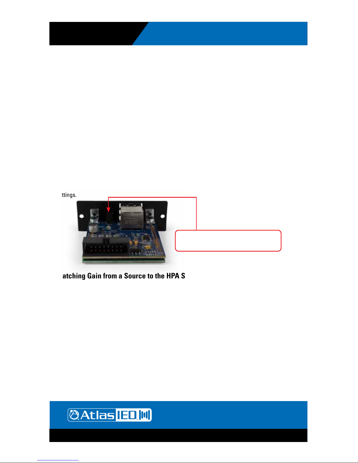
Selecting the dBFS Reference on the HPA-DAC4
The HPA-DAC4 comes with a choice of dBFS (Decibels Full Scale) gain selections of 0dBFS = 10dBu
and 0dBFS = 20dBu. Factory default for the card is 0dBFS = 20dBu. There is a 2-pin header on the
card that is the OdBFS gain selection. When a shunt is applied to the header, the 0dBFS = 20dBu
setting is engaged. When the shunt is removed the setting is 0dBFS = 10dBu. Most pro audio
equipment gains are in the range of 20dBu – 24dBu. Read the entire manual to understand these
settings.
Matching Gain from a Source to the HPA Series Amplier In a Dante® Network
Understanding the gain structure is very important to avoid clipping the audio signal or amplier
output. There are three potential ways to clip the signal chain.
1. Amplier Input Clipping - This occurs when the applied input signal exceeds the maximum input
level of the amplier input stage.
2. Amplier Output Clipping - Driving the amplier to maximum output level using the factory default
requires 0dBu or .775V of signal when the channel level control is set to maximum or the all up fully
clockwise. Note: AtlasIED recommends the level to be set with the level being controlled from
the source. Exceeding .775V or 0dBu level will cause the amplier output stage to clip.
3. Digital Clipping - This occurs when the 0dBFS levels are exceeded. This is very important to
understand. Several examples are provided to help understand digital to analog gain structure.
Note: AtlasIED recommends to always place a limiter set for 0dB in the signal path prior to the
Network Output of the transmitting device. This is the best way to prevent clipping the HPA-DAC4.
Shunt on 0dBFS = 20dBu, factory default
Shunt off 0dBFS = 10dBu
Owner’s Manual
HPA-DAC4
Dante
®
Accessory Card
AtlasIED.com – 4 –
Specifications are subject to change without notice.
1601 Jack McKay Blvd. • Ennis, Texas 75119 U.S.A.
Telephone: 800.876.3333 • Fax: 800.765.3435
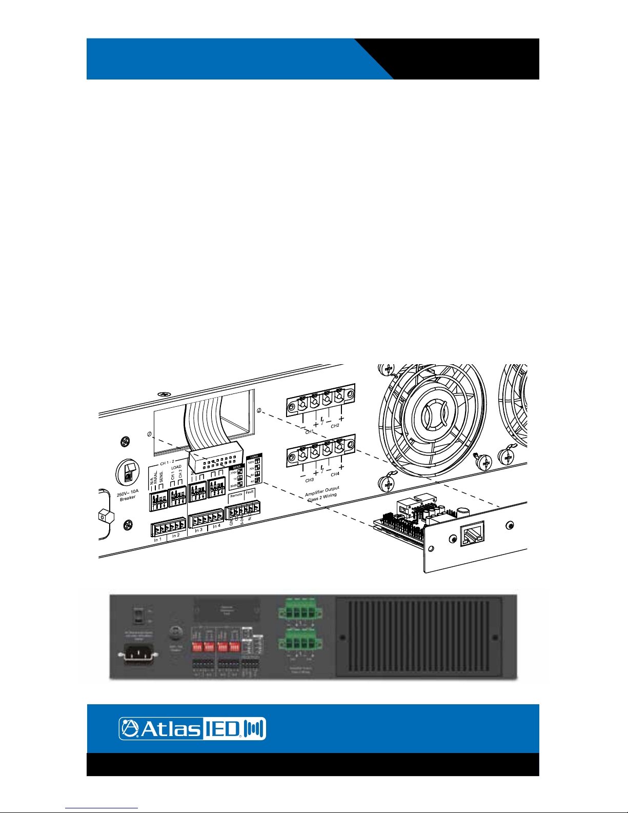
HPA-DAC4 Card Installation
Note: Accessory card installation must be done by a qualied technician.
1. Remove the HPA amplier from the AC mains source. Note: In standby mode there are DC voltages
present. The HPA amp must be removed from the AC Mains source in order to prevent damage to
the card or amplier.
2. Remove the two screws (M3 x 8mm Pan Head Black) holding the HPA Accessory blank panel.
3. Remove the ribbon cable from the cover plate.
4. Connect the accessory card to the ribbon cable by carefully aligning the ribbon cable connector to
the mating PCB connector. Do not force. If aligned correctly the cable will mate easily.
5. Carefully guide the accessory card into the slot without forcing the PCB or cable.
6. After the card is inserted and the accessory panel is ush to the chassis, align the two screw
holes and secure them together by inserting two M3 x 8mm screws.
 Loading...