

1/8
BlueBridge BBWP-TOUCH7
7" Touch Panel DSP Wall Controller Installation Guide
Thank you for purchasing the Atlas Sound BBWP-TOUCH7. The BBWP-TOUCH7 is part of the BlueBridge Wall Control (BBWP) family. All BBWP’s are
available with either a White (W) or Black (B) faceplate and the installation is the same for either version. This installation guide illustrates the different
mounting options available and the steps to properly install them. For operation of the BBWP-TOUCH7 refer to the BlueBridge Wall Controller Guide
located at www.atlassound.com/bluebridge.
All BlueBridge BBWP’s incorporate Ethernet communication protocol. They can be placed anywhere within a sound system as long as they are on the
same network and connected using a CAT5e cable to a switch. If the switch is a PoE type no external power to the BBWP is required. Each BBWP
requires 5VDC to power it and the external 5VDC power supply is included with each model if no PoE switch is available.
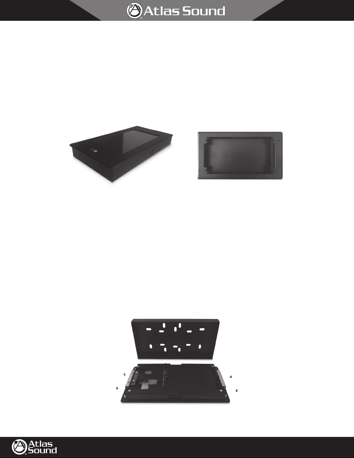
The BBWP-TOUCH7 comes with a surface mount back can (no flange) as show in Figure 01. Also included is an in-wall (flanged) back can and dress
bezel panel as shown in Figure 02.
Figure 01
There are four common ways to mount the BBWP-TOUCH7 described in this installation guide.
• Surface Mount
• Pre-Existing Construction In-Wall Mount
• New Construction In-Wall Mount
• Rack Mount
Figure 02
Surface Mount
The BBWP-TOUCH7 comes with a back can (no flange) pre-installed. This combination is designed to be secured to any flat surface. The back can has
several mounting holes and knock outs allowing for connection of the external DC power and CATe5 cables.
Follow these steps:
1. Remove the back can from the panel. On each side of the back can there are two M3 X 6 mm screws to be removed and set aside.
Note: Retain the screws for later use.
©2013 Atlas Sound L.P. All rights reserved. Atlas Sound is a trademark of Atlas Sound L.P. All other trademarks are the property of their respective owners. All specs are subject to change without notice. P/N 493857 ATS004748 RevA 10/13
1601 JACK MCKAY BLVD.
ENNIS, TEXAS 75119 U.S.A.
Figure 03
TELEPHONE: (800) 876-3333
FAX (800) 765-3435
AtlasSound.com

BlueBridge BBWP-TOUCH7
7" Touch Panel DSP Wall Controller Installation Guide
2. The BBWP-TOUCH7 can be powered by two methods.
A. External 5V DC external power supply (included)
B. PoE network switch. Using a PoE switch is recommended as it will supply both power and network connectivity.
1
3. Choose the best location for the DC power cable and/or CATe5 cable to access the back can. There are
can to facilitate wire feeding.
Figure 04
4. Be sure the PoE or external power supply is disconnected on the opposite end of the cable ensuring no DC power is present in the cables.
5. Run the cable(s) through the back can.
6. Secure the back can to the surface using one of the screw slots provided.
7. Connect the DC power and/or Ethernet CAT5e cable to the TOUCH7 as shown in Figure 05.
⁄2" knock outs on each side of the back
2/8
Power
Ethernet
Figure 05
8. Carefully place assembly into back can, making sure no cables are pinched or kinked.
9. Continue to the "Powering Up" section on page 8.
In-Wall Mount
The BBWP-TOUCH7 can be flush mounted in a wall surface. There are two methods described below, Pre-Existing Construction and New
Construction. Each method has different requirements and steps for completion. In-wall mounting requires cutting a hole in the wall and running
CAT5e cable inside the wall from a PoE enabled Ethernet switch to the desired location of the TOUCH7. The BBWP-TOUCH7 comes with a bezel
dress ring plate and a separate back can for in-wall installation. In-wall installation will require the included bezel ring to cover any wall cutout
imperfections.
©2013 Atlas Sound L.P. All rights reserved. Atlas Sound is a trademark of Atlas Sound L.P. All other trademarks are the property of their respective owners. All specs are subject to change without notice. P/N 493857 ATS004748 RevA 10/13
1601 JACK MCKAY BLVD.
ENNIS, TEXAS 75119 U.S.A.
Figure 06
TELEPHONE: (800) 876-3333
FAX (800) 765-3435
AtlasSound.com
3/8
BlueBridge BBWP-TOUCH7
7" Touch Panel DSP Wall Controller Installation Guide
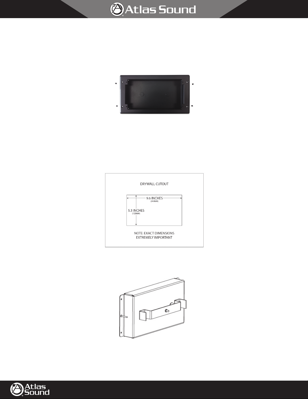
Pre-Existing Construction In-Wall Mounting
Follow these steps:
1. Separate the in-wall (flanged) back can from the bezel. Retain the four screws. See Figure 07.
Figure 07
2. Prepare the location where the BBWP-TOUCH7 will be installed.
A. Choose a location void of studs or conduit and where there is at least a 3.5" clearance behind the wall surface.
B. Ensure the CAT5e cable can be routed to the chosen location.
C. The cutout area required to install the TOUCH7 is 9.6" W x 5.3" H x 3.5" D (from the outside wall surface). Note: Make sure the cutout is
accurate or the cover bezel may not cover any cutting imperfections, see Figure 08.
Figure 08
10
3. Assemble the back can support bracket to the back can by inserting the
over tighten, leave finger loose. Refer to Figure 09.
4. Pull the cable through a back can cutout opening. Remember to include a good service loop in the cable to avoid having to disassemble and
remount later.
©2013 Atlas Sound L.P. All rights reserved. Atlas Sound is a trademark of Atlas Sound L.P. All other trademarks are the property of their respective owners. All specs are subject to change without notice. P/N 493857 ATS004748 RevA 10/13
1601 JACK MCKAY BLVD.
ENNIS, TEXAS 75119 U.S.A.
⁄32 x 1.5" screw through the can and thread it onto the bracket. Do not
Figure 09
TELEPHONE: (800) 876-3333
FAX (800) 765-3435
AtlasSound.com

4/8
BlueBridge BBWP-TOUCH7
7" Touch Panel DSP Wall Controller Installation Guide
5. Insert the back can into the wall and from the inside of the can rotate the screw until the bracket rotates vertically and straddles the back can. Pull
on the screw and finger tighten until the can is semi-snug to the wall.
Figure 10
6. There are two middle holes in the back can flanges to secure and align the can for visual straightness. Note: Be very careful because these holes
are very close to the drywall edge and if miss aligned drywall edge damage may occur. See Figure 11.
Figure 11
7. After the two front alignment screws are in place, tighten the inside center rear bracket screw until the box is snug and secure. Note: Do not over
tighten or the bracket will bend.
8. Remove the back can from the TOUCH7 panel. On each side of the back can there are two M3 X 6 mm screws to be removed and set them
aside, for later use.
Figure 12
9. Carefully set the TOUCH7 screen down on to a table with a protective cloth to prevent screen damage from occurring.
©2013 Atlas Sound L.P. All rights reserved. Atlas Sound is a trademark of Atlas Sound L.P. All other trademarks are the property of their respective owners. All specs are subject to change without notice. P/N 493857 ATS004748 RevA 10/13
1601 JACK MCKAY BLVD.
ENNIS, TEXAS 75119 U.S.A.
TELEPHONE: (800) 876-3333
FAX (800) 765-3435
AtlasSound.com

BlueBridge BBWP-TOUCH7
7" Touch Panel DSP Wall Controller Installation Guide
10. Align the bezel over the TOUCH7 rear threaded bolts on the rear side as shown in Figure 14.
5/8
Figure 13
11. Insert and tighten the four lock washers and M3 nuts as shown in Figure 15.
Figure 15
12. Chose the method to power the TOUCH7
A. External 5V DC external power supply (included).
B. PoE network switch. Using a PoE switch is recommended as it will supply both power and network connectivity.
13. Choose the best location for the DC power cable and/or CAT5e cable to access the in-wall (flanged) back can. There are
side of the back can to facilitate wire feeding.
Figure 14
1
⁄2" knock outs on each
Figure 16
14. Note: Make sure the PoE or external power supply is disconnected on the opposite end of the cable assuring no DC power is present in the
cables.
15. Run the cables through the back can.
©2013 Atlas Sound L.P. All rights reserved. Atlas Sound is a trademark of Atlas Sound L.P. All other trademarks are the property of their respective owners. All specs are subject to change without notice. P/N 493857 ATS004748 RevA 10/13
1601 JACK MCKAY BLVD.
ENNIS, TEXAS 75119 U.S.A.
TELEPHONE: (800) 876-3333
FAX (800) 765-3435
AtlasSound.com

BlueBridge BBWP-TOUCH7
7" Touch Panel DSP Wall Controller Installation Guide
16. Connect the DC power and/or Ethernet CAT5e cable to the TOUCH7 as shown in Figure 17.
Power
Ethernet
Figure 17
17. Place BBWP-TOUCH7 assembly into back can, carefully, making sure no cables are pinched or kinked.
18. Secure the assembly into the wall as shown in Figure 18.
6/8
19. Continue to the "Powering Up" section on page 8.
Figure 18
New Construction
For new construction that has exposed wall studs, the BBWP-TOUCH7 can be mounted to the studs using a universal telescoping box bracket that
must be purchased separately from one of several manufacturers that make them. Models will only work that mount between two studs as shown in
Figure 21.
Follow these steps:
1. Separate the in-wall (flanged) back can from the bezel. Retain the four screws. See Figure 19.
Figure 19
2. Prepare the location where the BBWP-TOUCH7 will be installed.
A. Choose a location void of studs or conduit and where there is at least 3.5" clearance behind the wall surface.
B. Ensure the CAT5e cable can be routed to the chosen location.
C. Place the universal telescoping box bracket between the studs. Make sure the depth of the bracket is set so the back can front flange will be
flush to the drywall.
©2013 Atlas Sound L.P. All rights reserved. Atlas Sound is a trademark of Atlas Sound L.P. All other trademarks are the property of their respective owners. All specs are subject to change without notice. P/N 493857 ATS004748 RevA 10/13
1601 JACK MCKAY BLVD.
ENNIS, TEXAS 75119 U.S.A.
TELEPHONE: (800) 876-3333
FAX (800) 765-3435
AtlasSound.com

7/8
BlueBridge BBWP-TOUCH7
7" Touch Panel DSP Wall Controller Installation Guide
D. The cutout area for the drywall required to install the TOUCH7 is 9.6" W x 5.3" H x 3.5" D (from the outside wall surface). Note: Make sure
the cutout is accurate or the cover bezel may not cover any cutting imperfections, see Figure 20.
E. After the drywall is cutout to fit the in-wall (flanged) back can, secure the back can to the universal telescoping box bracket by inserting two
screws through the back can into the bracket as shown in Figure 21. Additional screws can be applied to the back can flange if needed. See
page 6, steps 17, 18, and 19 to complete the mount of the BBWP-TOUCH7 into an in-wall (flanged) back can.
Figure 20
Figure 21
Rack Mount
Many installations require the audio system controls to be placed in an equipment rack. Atlas Sound offers an optional rack panel
(BB-TOUCH7-RP) that supports the BBWP-TOUCH7. It is designed to fit into a standard 19" rack and requires 4RU spacing. Follow the steps for
installation.
©2013 Atlas Sound L.P. All rights reserved. Atlas Sound is a trademark of Atlas Sound L.P. All other trademarks are the property of their respective owners. All specs are subject to change without notice. P/N 493857 ATS004748 RevA 10/13
1601 JACK MCKAY BLVD.
ENNIS, TEXAS 75119 U.S.A.
Figure 22
TELEPHONE: (800) 876-3333
FAX (800) 765-3435
AtlasSound.com

8/8
BlueBridge BBWP-TOUCH7
7" Touch Panel DSP Wall Controller Installation Guide
1. Remove the surface mount back can from the TOUCH7 panel. On each side of the back can there are two M3 X 6 mm screws that must also be
removed.
2. Align the four studs of the TOUCH7 panel to the rack panel and secure to the panel using the four washers and nuts as shown in Figure 23.
Figure 23
3. Chose the method to power the BBWP-TOUCH7. External 5V DC external power supply (included) or PoE switch.
4. Make sure the PoE or external power supply is disconnected on the opposite end of the cable assuring NO DC power is present in the cables.
5. Connect the DC Power and/or Ethernet CAT5e cable to the TOUCH7 as shown in Figure 24.
Figure 24
6. Place the assembly into the rack, carefully. Making sure no cables are pinched or kinked.
7. Continue on to the "Powering Up" section.
Powering Up the BBWP-TOUCH7
1. Apply power to the cables whether using PoE or external DCV.
2. Push the Power button and hold for 4 seconds. The screen will appear as in Figure 25. Note: The boot up home screen appearance may vary,
but a lit up screen indicates that the BBWP-TOUCH7 is ready to associate or "map" to a BlueBridge system design.
Figure 25
3. Refer to the BlueBridge Wall Controller Guide for mapping the device and associating a BlueBridge control panel program. Refer to the BlueBridge
Wall Control Reference Guide located at www.atlassound.com/bluebridge.
©2013 Atlas Sound L.P. All rights reserved. Atlas Sound is a trademark of Atlas Sound L.P. All other trademarks are the property of their respective owners. All specs are subject to change without notice. P/N 493857 ATS004748 RevA 10/13
1601 JACK MCKAY BLVD.
ENNIS, TEXAS 75119 U.S.A.
TELEPHONE: (800) 876-3333
FAX (800) 765-3435
AtlasSound.com
 Loading...