

Page 1
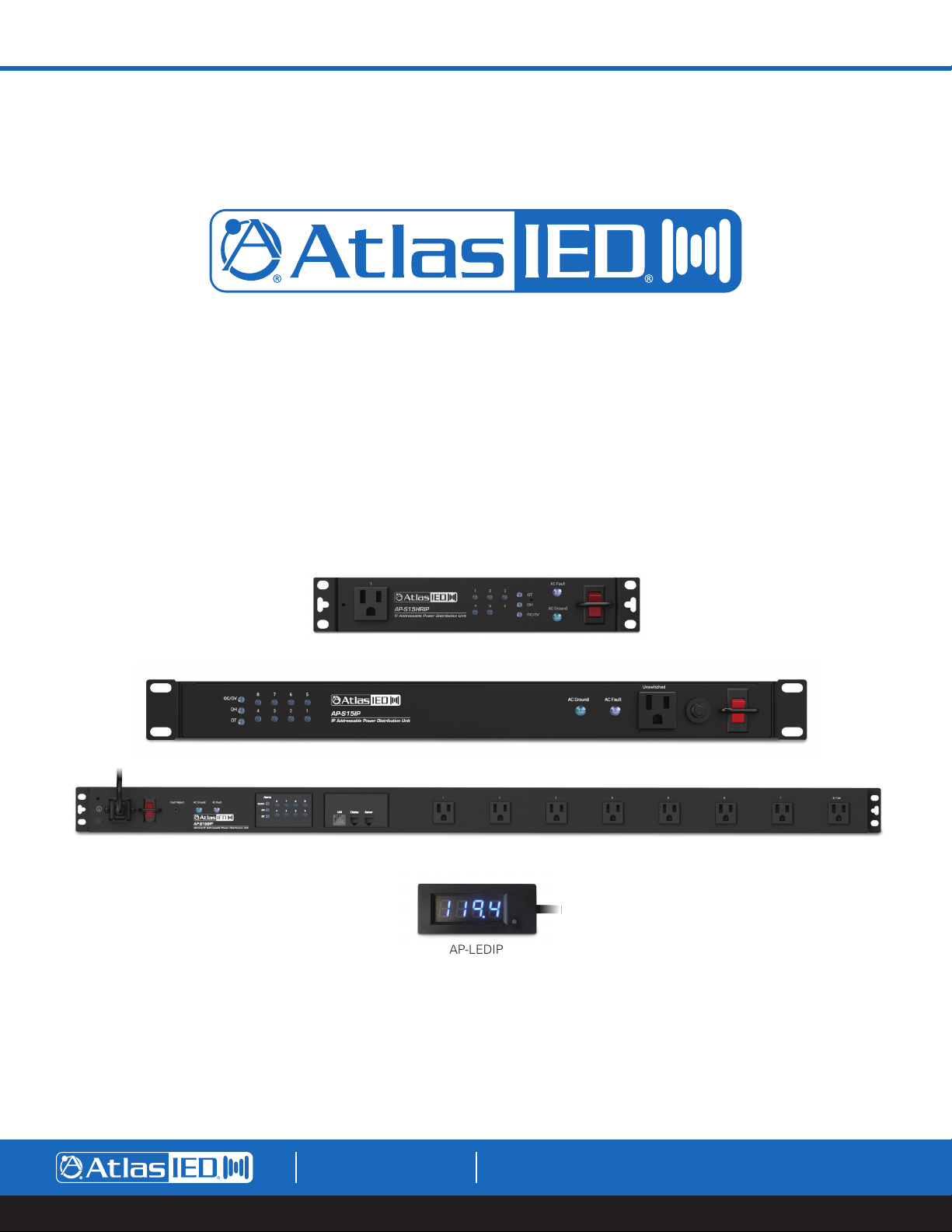
AP-S15HRIP / AP-S15IP / AP-S158IP
IP Power Distribution Systems
AP-S15HRIP
AP-S15IP
AP-S158IP
AP-LEDIP
1601 JACK MCKAY BLVD.
ENNIS, TEXAS 75119 U.S.A.
TELEPHONE: (800) 876-3333
SUPPORT@ATLASIED.COM
– 1 –
AtlasIED.com
Page 2

AP-S15HRIP / AP-S15IP / AP-S158IP
Owner’s Manual
Table of Contents
Important Safety Instructions ................................................................................................................................................................................. 3
Introduction ............................................................................................................................................................................................................ 5
Key Features and Applications ............................................................................................................................................................................... 6
Opening the Carton ................................................................................................................................................................................................ 6
System Overview ................................................................................................................................................................................................... 7
Features .................................................................................................................................................................................................................10
Installing the AP-IP Power Distribution System ................................................................................................................................................... 12
Accessing the WEB GUI Interface ....................................................................................................................................................................... 16
Finding the IP Address Using the LED Display .................................................................................................................................................... 16
Using the IP Discovery Software ......................................................................................................................................................................... 16
Logging Into the Unit ........................................................................................................................................................................................... 18
Status Settings WEB Page ................................................................................................................................................................................... 20
Alarm Settings WEB Page .................................................................................................................................................................................... 23
Scheduler Settings WEB Page.............................................................................................................................................................................. 26
Network Settings WEB Page................................................................................................................................................................................ 28
Configuration Settings WEB Page ........................................................................................................................................................................ 30
Updating the Firmware ......................................................................................................................................................................................... 31
3rd Party API Commands ..................................................................................................................................................................................... 31
Specifications ....................................................................................................................................................................................................... 32
Dimensional Drawings ......................................................................................................................................................................................... 34
Warranty ............................................................................................................................................................................................................... 40
1601 JACK MCKAY BLVD.
ENNIS, TEXAS 75119 U.S.A.
TELEPHONE: (800) 876-3333
SUPPORT@ATLASIED.COM
– 2 –
AtlasIED.com
Page 3
AP-S15HRIP / AP-S15IP / AP-S158IP
Owner’s Manual
Important Safety Instructions
The lightning flash with arrowhead symbol within an equilateral triangle,
is intended to alert the user to the presence of uninsulated “dangerous
voltage “ within the product’s enclosure that may be of sufficient
magnitude to constitute a risk of electric shock to persons.
WARNING: SHOCK HAZARD - DO NOT OPEN
AVIS: RISQUE DE CHOC ELÉCTRIQUE - NE PAS OUVRIR
WARNING: TO REDUCE THE RISK OF FIRE OR ELECTRIC SHOCK
DO NOT EXPOSE THIS EQUIPMENT TO RAIN OR MOISTURE
AVIS: NE PAS EXPOSER CE MATÉRIEL À LA PLUIE OU L’HUMIDITE
AFIN DE REDUIRE LE RISQUE D’INFLAMMATION OU DE CHOC ELÉCTRIQUE
1. Read these instructions.
2. Keep these instructions.
3. Heed all warnings.
4. Follow all instructions.
5. Do not use this device near water.
6. Clean only with dry cloth.
7. Do not block any ventilation openings. Install in accordance with the manufacturer’s instructions.
8. Do not install near any heat sources such as radiators, heat registers, stoves, or other device that produce heat.
9. Do not defeat the safety purpose of the polarized or grounding-type plug. A polarized plug has two blades with one wider than the other. A
grounding type plug has two blades and a third grounding prong. The wide blade or the third prong are provided for your safety. If the provided
plug does not fit into your outlet, consult an electrician for replacement of the obsolete outlet.
10. Protect the power cord from being walked on or pinched particularly at plugs, convenience receptacles, and the point where they exit from the
device.
11. Only use attachments / accessories specified by the manufacturer.
12. Use only with the cart, stand, tripod, bracket, or table specified by the manufacturer, or sold with the device. When a cart is used, use caution
when moving the cart / device combination to avoid injury from tip-over.
The exclamation point within an equilateral triangle is intended to
alert the user to the presence of important operating and maintenance
(servicing) instructions in the literature accompanying the product.
13. Unplug this device during lightning storms or when unused for long periods of time.
14. Refer all servicing to qualified service personnel. Servicing is required when the device has been damaged in any way, such as power-supply cord
or plug is damaged, liquid has been spilled, or objects have fallen into the device, the device has been exposed to rain or moisture, does not
operate normally, or has been dropped.
15. This product is equipped with a three-wire grounding-type plug, a plug having a third (grounding) pin. This plug will only fit into a grounding-type
power outlet. This is a safety feature. If you are unable to insert the plug into the outlet, contact your electrician to replace your obsolete outlet. Do
not defeat the safety purpose of the grounding-type plug.
16. WARNING: To reduce the risk of fire or electric shock, this device should not be exposed to rain or moisture and objects filled with liquids, such as
a vase, should not be placed on this device.
17. To completely disconnect this equipment from the mains, disconnect the power supply cord plug from the receptacle.
18. The mains plug of the power supply cord shall remain readily operable.
19. Protective earthing terminal. The apparatus should be connected to a mains socket with a protective earthing connection.
1601 JACK MCKAY BLVD.
ENNIS, TEXAS 75119 U.S.A.
TELEPHONE: (800) 876-3333
SUPPORT@ATLASIED.COM
AtlasIED.com
– 3 –
Page 4
AP-S15HRIP / AP-S15IP / AP-S158IP
Owner’s Manual
WARNING - When The Device Is In Use
• WARNING: For the terminals marked with symbol of may be of sufficient magnitude to constitute a risk of electric shock. The external wiring
connected to the terminals requires installation by an instructed person or the used of ready-made leads or cords.
• WARNING: The apparatus shall not be exposed to dripping or splashing and that objects filled with liquids, such as vases, shall not be placed on
apparatus.
• WARNING: The mains plug is used as disconnect device, the disconnect device shall remain readily operable.
• To prevent electric shock, do not remove the product cover as there are high voltage components inside. Refer all servicing to
AtlasIED.
• Should any of the following irregularities occur during use, immediately switch off the power, disconnect the power cord from the AC outlet and
contact AtlasIED. Do not to attempt to continue operation with the product as this may cause fire or electric shock:
• Smoke or strange smell coming from the unit.
• If the product falls or the case is damaged.
• If water or any metallic objects falls into the product.
• If the power supply cord is damaged in any way.
• If the unit is malfunctioning.
• Do not insert or drop metallic objects or flammable materials into the ventilation holes of the product's cover, as this may result in electric shock or
fire.
• Do not place any containers with liquid or metallic objects on the top of the product. If any liquid spills into the unit, fire or electric shock may result.
• Never operate this product or touch the power supply cord during an electrical storm, electric shock may result.
• Never exceed the power rating on the product when connecting equipment. Fire and/or property damage may result.
• Operate the product only with the voltage specified on the unit. Fire and/or electric shock may result if a higher voltage is used.
• Do not modify, kink, or cut the power cord. Do not place the power cord in close proximity to heaters and do not place heavy objects on the power
cord, including the product itself, doing so may result in fire or electrical shock.
• Ensure that the safety ground terminal is connected to a proper ground. Never connect the ground to a gas pipe as a catastrophic disaster may
result.
• Be sure the installation of the product is stable, avoid slanted surfaces as the product may fall and cause injury or property damage.
CAUTION - When Installing The Product
• Plugging in or unplugging the power cord with wet hands may result in electric shock.
• Never move the unit with the power cord plugged into the wall, as damage to the power cord may result.
• When unplugging the cord from the wall, grasp the plug, NOT the cord.
• Never install this product in humid or dusty locations, nor in direct sunlight, near sources of heat, or in areas where sooty smoke or steam are
present. Fire and electric shock may result.
• Keep all sides of the unit at least 31/2" away from objects that may obstruct air flow to prevent the unit's internal temperature rise.
CAUTION - When The Product Is In Use
• Never place heavy objects on the product, causing it to fall and/or break, resulting in personal injury and property damage. In addition, the product
itself may fall and cause injury and property damage.
• Contact AtlasIED for instructions on cleaning the inside of the unit. Large accumulations of dust inside the unit may result in heat buildup and fire.
• Ensure that the power supply plug is securely plugged into the wall outlet. Never allow dust to accumulate on the power plug or inside the wall
outlet.
• When cleaning the unit or the unit is not to be operated for an extended period, unplug the power cord from the wall.
1601 JACK MCKAY BLVD.
ENNIS, TEXAS 75119 U.S.A.
TELEPHONE: (800) 876-3333
SUPPORT@ATLASIED.COM
– 4 –
AtlasIED.com
Page 5

AP-S15HRIP / AP-S15IP / AP-S158IP
Owner’s Manual
Introduction
Thank you for purchasing this AtlasIED Network IP Power Distribution system. This document is designed to provide a high-level overview of the
network IP power distribution system product family, including common features to all models. AtlasIED recommends visiting
www.atlasied.com/ip-enabled-power-distribution and downloading the AP-IP discovery software to a computer running the Windows® operating
system. Other related guides for the AtlasIED AP-IP Power Distribution systems can also be downloaded there.
The AP-IP power distribution systems are remote or locally controlled AC power distribution management systems with power conditioning, surge
protection and LAN monitoring. Each AP-IP features a local display and a web-based user interface (UI) that can monitor voltage, current, temperature
and humidity. Through the UI, alarms can be set to alert users when a fault condition has occurred via the network UI or fault contacts. Models
AP-S15IP and AP-S15HRIP include rear outlets that are programmable and can be scheduled to sequence On / Off individually or in groups on a
24-hour / 7-day schedule. Each AC outlet has a front panel LED status indicator that can also be used to manually turn the outlet On or Off. This feature
can be disabled via the UI for increased security. A front panel unswitched AC outlet is also included.
The AP-IP power distribution systems can be automatically identified when connected to a LAN using the AP-IP discovery software running on a
connected computer running Windows
temperature and humidity data within the rack in real time. The AP-LEDIP can also be used to read the IP address of the unit, eliminating the need to
use the discovery software. The external temperature / humidity probe can be used to monitor rack climate conditions to activate a cooling system if
needed. Programable alarm settings are easily configured with fault logs and fault reporting via the UI. The unit or individual outlets can be tested or
monitored for active status via the Auto Ping Reset feature.
The AP-IP power distribution systems feature filtering for unwanted Radio Frequency Interference (RFI) that is commonly introduced into AC lines by
nearby radio transmitters or wireless products that commonly deteriorate video signals and that can be heard as static in audio signals.
A removable 2m, 14-gauge IEC power cord with a retainer bracket is supplied with each unit to allow the installer to use a longer or shorter power cord
length based on installation requirements (sold separately).
Key Features
®
. The AtlasIED model AP-LEDIP, LED display, is included to provide a visual reference of the voltage, current,
• 15A Rack Mount Power Conditioner with LAN Network Monitoring & Control
• On-board IP Address Display
• IP Discovery PC Software
• Circuit Breaker Protection @ 15A
• Individual Outlet On / Off Manual Switch and LED Indicator (Enable / Disable)
• Removable 15A IEC Power Cord with Retainer Bracket
• AC Mains RFI Noise Filtering & Surge Protection
• Earth Ground Fault Connection Indicator
• Web User Interface
• DHCP or Static IP Addressable
• Voltage, Current, Temperature and Humidity Monitoring Capability
• Over Voltage, Current, Temperature and Humidity Alarm Setting
• Each Outlet Can be Individually Managed Remotely
• User Definable Names for Each Outlet
• User Definable Delay Time and Sequence
• Temperature Setting for AC Fan Activation
• Fault Log with Reporting
• Fault Reporting GPIO Port
• Password Protection
• Individual Outlet Auto Ping Reset
• User Definable 24 / 7 Schedules of Individual Outlets to Switch Devices On or Off
• 3-Meter Humidity / Temperature Probe
• AP-LEDIP Display Panel Shows Voltage, Current, Temperature, Humidity and IP Address
1601 JACK MCKAY BLVD.
ENNIS, TEXAS 75119 U.S.A.
TELEPHONE: (800) 876-3333
SUPPORT@ATLASIED.COM
– 5 –
AtlasIED.com
Page 6
AP-S15HRIP / AP-S15IP / AP-S158IP
Owner’s Manual
Applications
The flexible AP-IP power distribution system family was designed with features enabling them to be used in a variety of applications. They can be used
for AC distribution or for system power and protection against voltage surges or dropouts. They are ideal for systems that need to be powered On or
Off at specific times to conserve energy or to monitor the system for faults and operability. The AP-IP power distribution systems also feature power
conditioning and surge protection. The following are examples of applications where the AP-IP power distribution systems can be used:
• IT Facilities
• Office Buildings
• Restaurants
• Houses of Worships
• Educational Facilities
• Industrial Applications
Opening the Carton
Each unit carton contains an AP-IP power distribution system, power cord, power cord retainer clip & screws, temperature / humidity sensor probe,
fault cable and LED data display. DO NOT plug the unit into an AC mains source until the following steps have been completed.
1. Install and secure the unit into the equipment rack.
2. Ensure the power switch is in the Off or down position.
3. Install the temperature / humidity probe in the rear port marked Sensor. Note: This is very important, or the unit will not function, and the front
panel alarm LEDs will flash.
4. Install the remote LED Data display into the rear port marked Display.
5. Fault Report Port & Cable - This 3.5mm port mates with the supplied Fault cable. The 3-meter cable is 2-conductor with the wire ends bare
allowing it to interface with an external device that supports contact closure GPIO. The port state is normal closed (NC) when the unit is active and
opens when the AC power is Off or an alarm fault is detected such as voltage, current, temperature or humidity.
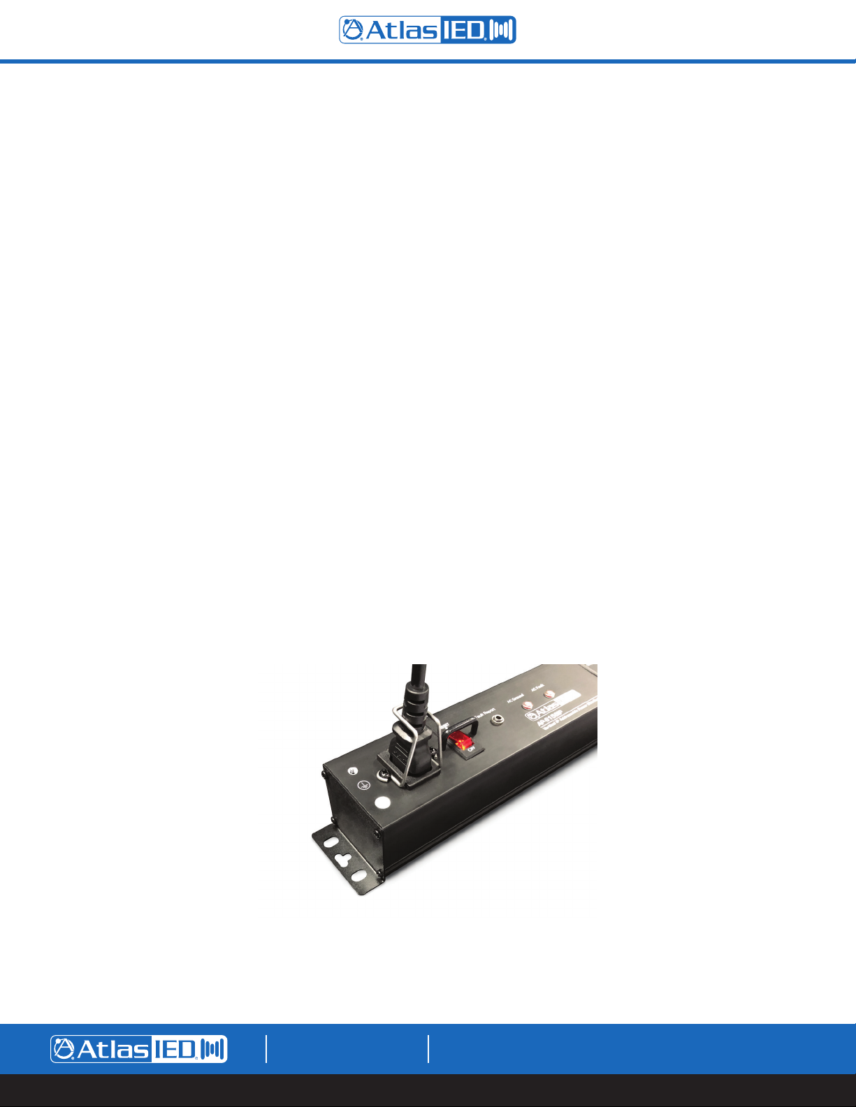
6. Install the power cord and retainer clip. The retainer clip mounts over the power cord IEC end and is secured by two screws. Below is an
illustration showing how the power cord bracket mounts to the chassis.
1601 JACK MCKAY BLVD.
ENNIS, TEXAS 75119 U.S.A.
TELEPHONE: (800) 876-3333
SUPPORT@ATLASIED.COM
– 6 –
AtlasIED.com
Page 7
AP-S15HRIP / AP-S15IP / AP-S158IP
Owner’s Manual
AP-IP Power Distribution System Family Overview
The AP-IP power distribution system series all have the same features with the only differences between models being the rack mounting type. The
AP-S158IP is a vertical mount power strip with eight programable outlets. The AP-S15IP is a 19" rack mount power strip with eight programable rear
outlets and 1 front panel unswitched outlet. The AP-S15HRIP is half rack, rack mount power strip with five programable rear outlets and 1 front panel
switched outlet.
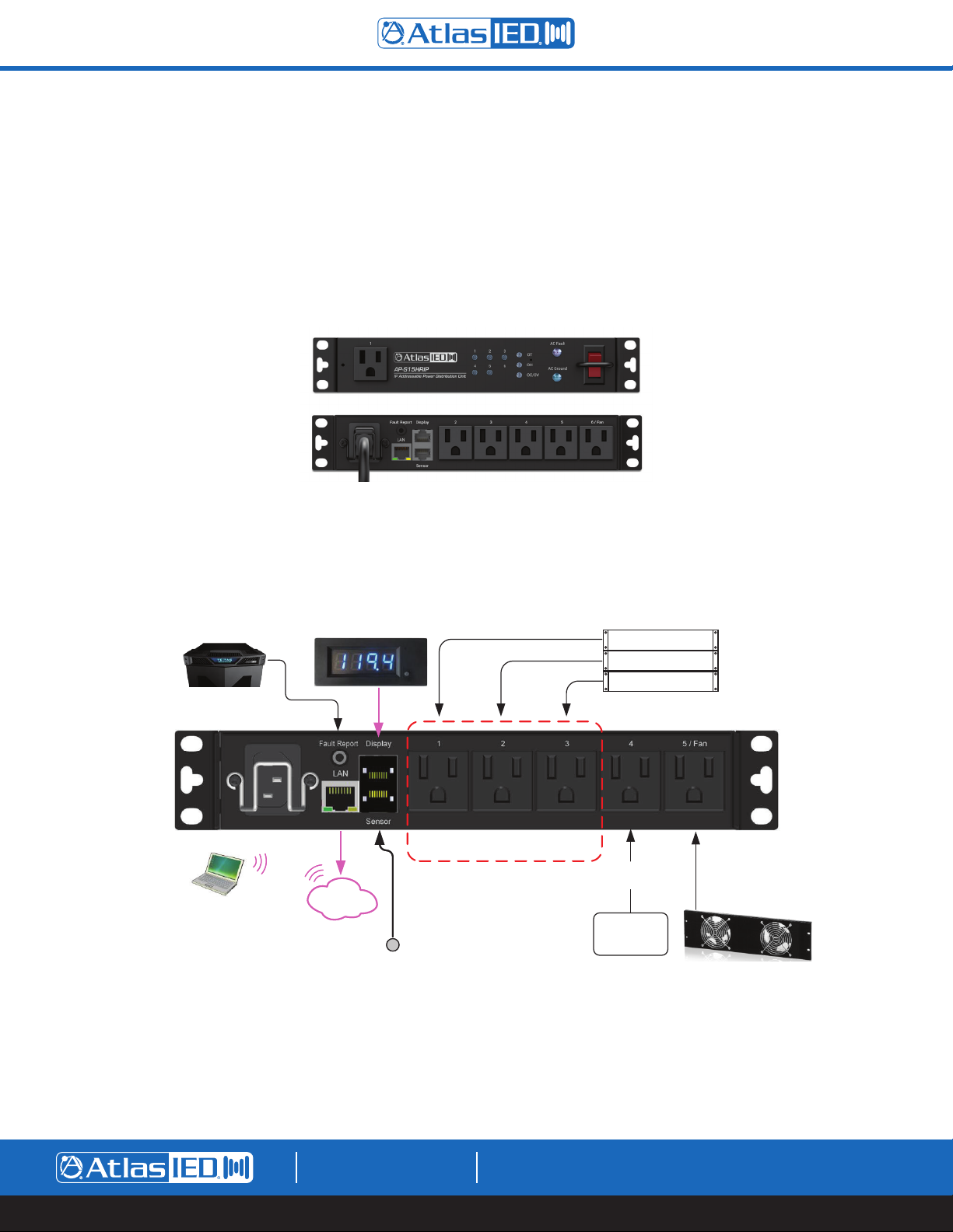
AP-S15HRIP
The AP-S15HRIP is half rack width rack mount power distribution system with five programable rear outlets and 1 front panel switched outlet.
Fault Repor t co nnecte d to
Texas Tough Rack will
Change Logo Colo r when
Fault is detected
AP-LEDIP
Included Display
Local Lan
Local Lan
Router
Router
Outle ts 1 thru 3 - Group Sequ enced
Progr ammed
Temperature ProbeTemperature Probe
EQUI PMEN T RAC K
WIRELE SS MIC
RECEI VER
SOURC E MEDIA
PLAYER
POWER AM P-1
Progr ammed
for Alway s O N
Contr ol
Syste m
Progr ammed
for Fan using
Temp Pr obe
AtlasIED EFP3 -2
Dual Fan Rack Mount
1601 JACK MCKAY BLVD.
ENNIS, TEXAS 75119 U.S.A.
TELEPHONE: (800) 876-3333
SUPPORT@ATLASIED.COM
– 7 –
AtlasIED.com
Page 8
AP-S15HRIP / AP-S15IP / AP-S158IP
Owner’s Manual
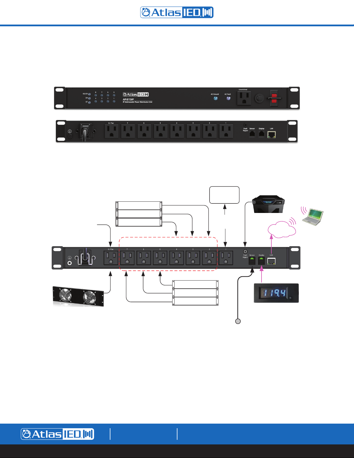
AP-S15IP
The AP-S15IP is a 19" rack mount power distribution system with eight programable rear outlets and 1 front panel unswitched outlet.
Fault Repor t co nnected to
Texas Tough Rack will
Change Logo Colo r when
Fault is detected
Local Lan
Local Lan
Router
Router
Progr ammed
for Fan using
Temp Pr obe
EQUI PMEN T RAC K
WIRE LESS MI C
RECEI VER
SOURC E MEDI A
PLAYER
SIGNAL PROCESSOR
Outle ts 2 thru 7 - Group Sequenc ed Progra mmed
Contr ol
System
Progr ammed
for Always
ON
AtlasIED EFP3-2
Dual Fan Rack Mount
1601 JACK MCKAY BLVD.
ENNIS, TEXAS 75119 U.S.A.
EQUI PMEN T RAC K
POWER AMP-1
POWER AMP-2
POWER AMP-3
Temperature ProbeTemperature Probe
TELEPHONE: (800) 876-3333
SUPPORT@ATLASIED.COM
AP-LEDIP
Included Display
AtlasIED.com
– 8 –
Page 9
AP-S15HRIP / AP-S15IP / AP-S158IP
Owner’s Manual
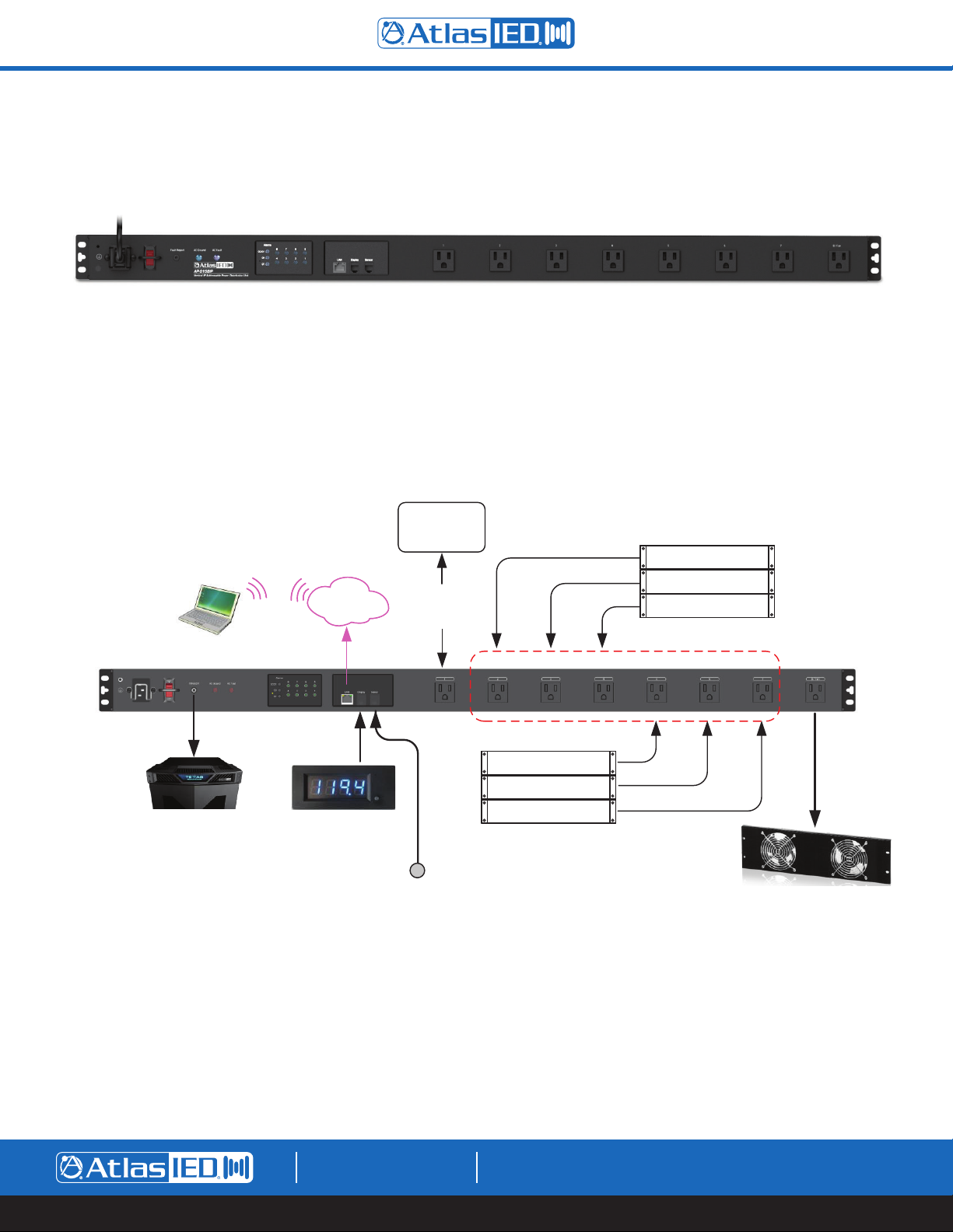
AP-S158IP
The AP-S158IP is a vertical mount power distribution system with eight programable outlets.
Fault Report connected to
Texas Toug h Rack wil l
Change Logo Color when
Fault is detected
Local Lan
Local Lan
Router
Router
AP-LEDIP
Included Display
Contr ol
System
Programmed
for Always
ON
Temperature Pr obe
EQUI PMEN T RACK
WIRE LESS MI C
RECEI VER
SOURC E MEDI A
PLAYER
SIGNAL PROCESSOR
Outle ts 2 thru 7 - Group Sequenced Programmed
EQUI PMEN T RACK
POWER AMP-1
POWER AMP-2
POWER AMP-3
Dual Fan Rack Mount
Progr ammed
for Fan using
Temp Probe
AtlasIED EF P3-2
1601 JACK MCKAY BLVD.
ENNIS, TEXAS 75119 U.S.A.
TELEPHONE: (800) 876-3333
SUPPORT@ATLASIED.COM
– 9 –
AtlasIED.com
Page 10
AP-S15HRIP / AP-S15IP / AP-S158IP
Owner’s Manual
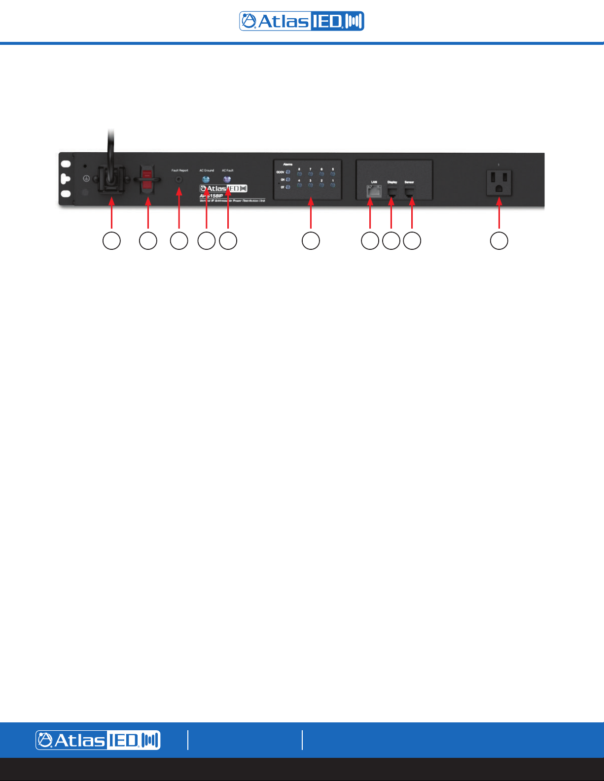
Unit Features
AP-S158IP Shown
1 2 10 97865 4 3
1. AC Mains Input - Connect the IEC 14-Gauge 6' (2m) power cord to a 15A 120VAC outlet to provide power to the unit. An IEC power cord retainer
clip is included to prevent accidental removal of the power cord from the unit.
2. AC Mains Power Switch and Breaker - To turn the power strip ON or OFF, press the switch up to the ON position or down to the OFF position.
When in the ON position, AC voltage is present, and the power switch will illuminate red. Note: This does not mean the switched AC outlets are
active. For the switched AC outlets to be active, each outlet needs to be configured in the web interface. Factory default configuration is that all
outlets will sequence ON when the power switch is turned ON. The AP-IP power distribution systems incorporate a power switch protection bar
to prevent an accidental pressing of the power switch.
This AC Mains Power switch also serves as the AC Mains breaker. The 15A rated breaker will open if the combined draw of all AC outlets exceeds
15 amps. Note: The breaker is designed to exceed its rating for a short period of time. If the breaker is tripped, you must first remove the load
from the power strip and then turn the switch OFF and then to ON to reset.
3. AC Fault Indicator - Although the clamping suppression circuit virtually assures protection from most transient voltage spikes and surges, nature
has a way of occasionally creating electrical forces that are beyond the capabilities of any device to absorb without some degree of damage. In
the rare instance that this occurs, and the circuit has been damaged, the “AC Fault” LED indicator will illuminate red. The unit disables all AC
outlets until it is repaired. Be advised that activation of this fault condition, the associated repair is not covered under warranty. Note: If the AC
Fault LED is illuminated, it is important to have all equipment that was connected to that AC mains line inspected for proper operation.
4. Ground Status Indicator - This LED will illuminate red when the power strip has no Earth Ground Connection on the Earth Ground Pin of the
AC mains power cord. Note: If there is no Earth ground connection the LED will illuminate and the AC wall outlet must be repaired by an
electrician before continuing. Note: Using a good quality power cord is essential to getting a solid ground connection. There are many cheap power
cords that do not have a good ground connection that may cause the Ground LED to illuminate.
5. Fault Report Port - This 3.5mm port mates with the supplied Fault cable. The cable is a 3-meter, 2-conductor with the wire ends bare allowing to
interface with an external device that supports contact closure GPIO. The port state is normal closed (NC) when the unit is active and opens when
the AC Power is OFF or an alarm fault is detected such as voltage, current, temperature or humidity. This port is also ideally suited to interface with
the AtlasIED Texas Tough rack series. When a fault is detected, the contacts open up and the LEDs in the crown (Top) of the Texas Tough rack
change color to indicate there is an issue within the rack.
6. LAN (Local Area Network) Ethernet Port - Connect the amplifier to the network, local computer, or router/switch using CAT5 cable to access the
unit’s web interface and control settings.
7. Sensor Probe (Temperature & Humidity) Port - Each unit comes with a temperature/humidity probe that interfaces with the sensor port. This 9ft
(3m) cable MUST be plugged into the sensor port or the unit will not function, and the alarm LEDs will flash ON/OFF. The sensor is located in
the end of the cable and needs to be placed in the rack where the temperature or humidity are to be monitored. In most situations the best
location is near the top of the rack. Both temperature and humidity can be monitored locally when using the AP-LEDIP display or remotely by using
the web interface. The temperature and humidity data can be used to trigger alarms or be programmed to turn on AC Outlet #8 to activate a fan to
cool the rack.
1601 JACK MCKAY BLVD.
ENNIS, TEXAS 75119 U.S.A.
TELEPHONE: (800) 876-3333
SUPPORT@ATLASIED.COM
– 10 –
AtlasIED.com
Page 11
AP-S15HRIP / AP-S15IP / AP-S158IP
Owner’s Manual
Unit Features
8. Remote LED Display Port (Included Accessory) - This display control port mates with the included LED display, model AP-LEDIP. This display will
provide a visual reference for the voltage, current, temperature or humidly data within the rack in real time. The AP-LEDIP can also be used to read
the IP address of the unit eliminating the need to use the discovery software.
9. AC Power Programmable Outlets - The AP-S158IP and the AP-S15IP feature eight programable NEMA 5-15P AC switched outlets and the
AP-S15HRIP has five. These switched AC outlets are “live” when the front panel power switch is in the ON position and the outlet is activated via
the WEB interface or by pressing the AC outlet indicator ON/OFF switch (see AC outlet Switches & indicators) If the AC outlet’s corresponding
outlet indicator is illuminated green, the AC outlet is active and AC voltage will be present.
10. AC Outlet ON/OFF Switches and Indicators - Each unit includes AC Outlet ON/OFF switches that also serve as outlet active indicators. Press
the corresponding outlet switch firmly to manually turn a specific AC Outlet ON or OFF. The switch will illuminate green when the corresponding
AC outlet is on. The AC outlets can also be activated by using the interface. Note: The AC Output ON/OFF function can be programmed to be
disabled in the web interface.
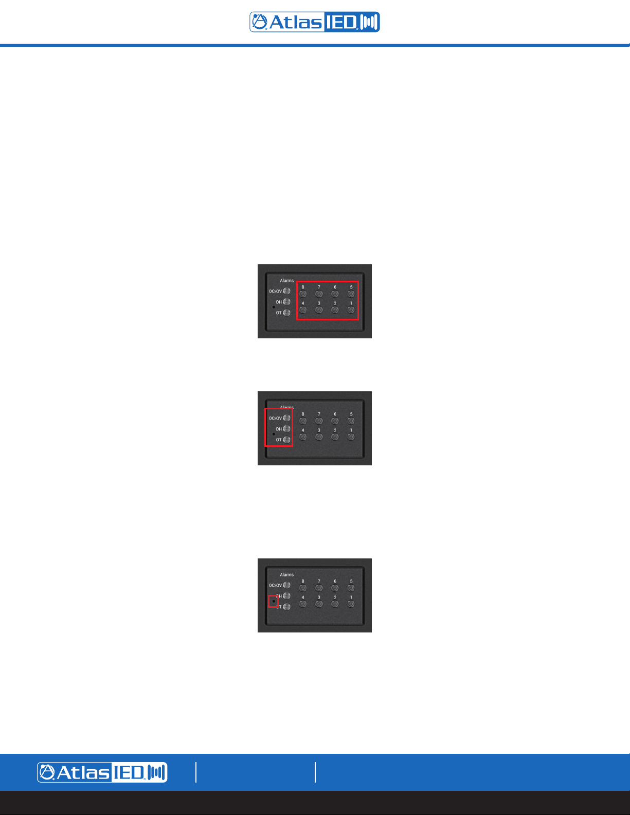
Alarm Indicators - The AP-IP power distribution systems feature alarms for the following: Over & Under Voltage, Over Current, Over Temperature
and Over Humidity. All alarm settings are programmed in the web UI. If an alarm is activated, the associated LED will illuminate and the fault
contacts will open.
Factory Reset Switch - The Factory Reset switch is located in the front panel as indicated in the picture below. Insert a small object like a paper
clip into the hole to access the switch. Gently press and hold the switch inward for 3 seconds, then release. The unit’s outlets and display will shut
off and turn back on indicating the Factory Reset was successful. The Factory Reset switch will reset all functions that were previously
programmed and will also reset the unit to accept DHCP IP address. Note: Any custom passwords will be replaced by the last 4 digits of the MAC
address. Before resetting the unit, it is important to write down any special settings that may have been adjusted. Refer to the section Logging
into the Unit for details.
11. Unswitched Outlet (Not Shown in AP-S158IP)
• A Unswitched AC outlet is not programable
• The AP-S15IP has an unswitched AC outlet that is always live even if the AC mains power switch is in the OFF position. This outlet is protected
by the AC mains breaker, surge protection and by RF filtering.
• The AP-S15HRIP has a switched AC outlet that is turned ON/OFF with the AC mains power switch. This outlet is protected by the AC mains
breaker, surge protection and by RF filtering
1601 JACK MCKAY BLVD.
ENNIS, TEXAS 75119 U.S.A.
TELEPHONE: (800) 876-3333
SUPPORT@ATLASIED.COM
AtlasIED.com
– 11 –
Page 12

AP-S15HRIP / AP-S15IP / AP-S158IP
Owner’s Manual
Installing the AP-IP Power Distribution System
Note: AtlasIED requires that the AP-IP Power Distribution Systems be installed by a qualified electrician or IT technician. Before starting installation,
the manual must be read in its entirety.
Plugging Equipment Into An Outlet
After the unit has been installed in a rack, equipment can be connected to it. There are a few things to consider before starting. Note: The AtlasIED IP
power distribution systems must be installed by qualified technician. Before proceeding, visit atlasied.com to obtain an installation manual. Read the
manual entirely before proceeding with the installation of this product.
1. Total current draw of the power strip cannot exceed 12A continuous signal or 15A IT / Audio applications or the AC Mains 15A Breaker may trip.
Every product should have a current draw rating, add up all the equipment’s total current and make sure it doesn’t exceed 1440W.
Note: Pay special attention to audio amplifiers, they typically consume the most power compared to processors or controllers.
2. Audio amplifiers should turn on last, and off first in a sequence.
3. If a computer or router needs to be on all of the time, an outlet can be programmed to stay on for that operation.
Rack Mounting the AP-S15HRIP
A rack kit is included with the purchase of the AP-S15HRIP. The AP-S15HR width fits most rack cabinets that are classified as half-width. There are no
industry standards for these types of racks and rack widths may vary between manufactures. The AP-S15HRIP can be mounted into an AtlasIED wall
mount half-width rack or a 19” rack. The AP-S15HRIP can be mounted with any AtlasIED 1/2 RU products or mounted alone, but requires a rack mount
kit. For half rack designs there needs to be a minimum distance of 9.25” between rails. AtlasIED recommends checking the distance between the rack
rail opening before proceeding. Note: Two AP-S15HRIP units cannot be mounted side by side.
Kit Contains
• Qty 2 Rack ears
• Qty 8 M4 x 8mm Pan head rack ear screws
• Qty 1 Rack extension plate for single unit mounting
• Qty 2 M4 x 10mm pan head black screws to combine extension plate to rack ear
• Qty 2 M4 hex nuts for screws to secure screw to extension plate and rack ear
• Qty 2 Top joiner plates
3
• Qty 8 4-40 x
• Qty 1 Front panel joiner plate
• Qty 2 4-40 x
/8 flat head black screws to secure top joiner plate
3
/8 flat head black screws to secure front panel joiner plate
1601 JACK MCKAY BLVD.
ENNIS, TEXAS 75119 U.S.A.
TELEPHONE: (800) 876-3333
SUPPORT@ATLASIED.COM
– 12 –
AtlasIED.com
Page 13

AP-S15HRIP / AP-S15IP / AP-S158IP
Owner’s Manual
Configuration 1 - Mounting a Single 1 RU Model
1. Remove amplifier from electrical source.
2. Remove the four feet.
3. Align and secure the chassis extension plate to a rack mount ear with the enclosed screws and nuts.
4. Locate the two open holes on each side of the amp located towards the front panel.
5. Align the enclosed rack mount ear and extension assembly to the chassis holes located in step 4.
6. Use the enclosed chassis screws to attach the rack ears and extension assembly to the chassis. Secure firmly, do not over tighten. Repeat step
for opposite chassis side.
7. Disregard extra pieces.
8. Ready for rack installation. Note: It is important the amplifiers have the proper clearance around it for proper heat dissipation. Always allow at least
1.75" around the amplifier for to assure safe operation. Never mount an amplifier in an enclosed air tight rack. All racks must have air vents on all
sides or forced air cooling to assure proper heat dissipation.
M4 x 10mm Pan Head Screw
M4 x 8mm Pan Head Screw
M4 Hex Nut
M4 x 8mm Pan Head Screw
1601 JACK MCKAY BLVD.
ENNIS, TEXAS 75119 U.S.A.
TELEPHONE: (800) 876-3333
SUPPORT@ATLASIED.COM
– 13 –
AtlasIED.com
Page 14

AP-S15HRIP / AP-S15IP / AP-S158IP
Owner’s Manual
Configuration 2 - Mounting 2 1RU Models
Note: Not all 1RU half rack models can be joined next to each other. The following combinations can be joined: ASP-MG2240, DPA102PM, MA40G,
MA60G, PA40G, PA60G, AP-S15HR, AP-S15RTHR, and AP-S15HRIP are interchangeable. Note: Two AP-S15HR units cannot be rack mounted together
side-by-side. Call AtlasIED for other models not listed.
1. Remove amplifier from electrical source.
2. Remove the four feet.
3. Align and secure two chassis joiner plates with the enclosed screws to the top of units. Note: Must install both plates, one towards the front and
one towards the back.
4. Locate the two open holes on each side of the amp located towards the front panel.
5. Align the enclosed rack mount ear to the chassis holes located in step 2.
6. Use the enclosed chassis screws to attach the rack ears to the chassis. Secure firmly, do not over tighten. Repeat step for opposite chassis side.
3
7. Install the front panel joiner plate using the two 4-40 x
is installed in the rack.
8. Disregard extra pieces.
9. Ready for rack installation. Note: It is important the amplifiers have the proper clearance around it for proper heat dissipation. Always allow at least
1.75" around the amplifier for to assure safe operation. Never mount an amplifier in an enclosed air tight rack. All racks must have air vents on all
sides or forced air cooling to assure proper heat dissipation.
/8 flat head black screws. Note: The front panel joiner plate can be removed after the unit
3
4-40 x
/8 Flat Head Screw
Note: Not all 1RU half rack models
can be joined next to each other.
Refer to the list above or call
AtlasIED Customer Service.
1601 JACK MCKAY BLVD.
ENNIS, TEXAS 75119 U.S.A.
TELEPHONE: (800) 876-3333
SUPPORT@ATLASIED.COM
– 14 –
AtlasIED.com
Page 15

AP-S15HRIP / AP-S15IP / AP-S158IP
Owner’s Manual
Front Panel Joiner Plate
Not used on PA702 or PA1001G
4-40 x 3/8 Flat Head Screw
1601 JACK MCKAY BLVD.
ENNIS, TEXAS 75119 U.S.A.
TELEPHONE: (800) 876-3333
SUPPORT@ATLASIED.COM
– 15 –
AtlasIED.com
Page 16

AP-S15HRIP / AP-S15IP / AP-S158IP
Owner’s Manual
Accessing the Unit’s Web UI Interface
The AtlasIED AP-IP power distribution system’s GUI control panel is designed to be accessed via the LAN (Local Area Network) or local computer.
External software is not required for operation. The Web browser UI control interface software is embedded in the unit. Remote access to the device
can be set up through a VPN connection by working with the client or facility’s IT administrator.
Finding the Unit’s IP Address
There are two methods to find the unit’s IP address in DHCP mode, using the AP-LEDIP display or by using the discovery software. Note: All AtlasIED
AP-IP power distribution systems ship (factory default) in DHCP mode.
1. AP-LEDIP IP Discovery
Using the AP-LEDIP external display is the fastest way to discover the IP Address. Plug the AP-LEDIP display into the unit’s display port. On the
display, press and hold down the viewing selection button until the IP address starts to scroll across the display. An IP address read out example
would be 192.168.1.138.
Magnetic display can be placed
outside of the door when closed.
Press and hold the button to display
the IP Address. Press once to
change the display data.
2. Discovery Software
The user can search the LAN for connected units using a specified range of IP addresses within the LAN. To do so, the router’s range assignment
of IP address must be known. This IP address range must be entered into the AP-IP Discovery Software. An IT technician can provide the IP
address range assigned or, if the computer Network Interface Card (NIC) card is on the same LAN, this IP address can be selected and it will auto
fill the range of IP addresses that are needed to be scanned. The discovery software can be found at
www.atlasied.com/ip-enabled-power-distribution.
1601 JACK MCKAY BLVD.
ENNIS, TEXAS 75119 U.S.A.
TELEPHONE: (800) 876-3333
SUPPORT@ATLASIED.COM
AtlasIED.com
– 16 –
Page 17

AP-S15HRIP / AP-S15IP / AP-S158IP
Owner’s Manual
IP Scan Range
In this section of the discovery software enter the Start and End range of the IP address search. Select the drop-down arrow in the “Select NIC”
window. The number listed in this window is the IP address of the computer’s NIC. Select the IP address and it will auto fill the Start and End
IP fields. Note: The NIC auto fill feature only works with computers running the Windows
running MacOS.
• Click on the “Select NIC” drop down arrow
• After the NIC IP address is selected the Start IP & End IP fields will autofill
®
operating system and not work with Apple® computers
• Select “Start Scan” and the discovery software will search the LAN for AP-IP products within the IP range listed. Units discovered will be listed
by their IP address, unit name, model name & MAC address
1601 JACK MCKAY BLVD.
ENNIS, TEXAS 75119 U.S.A.
TELEPHONE: (800) 876-3333
SUPPORT@ATLASIED.COM
AtlasIED.com
– 17 –
Page 18

AP-S15HRIP / AP-S15IP / AP-S158IP
AP-S15HRIP
IP Addressable Power Distribution Unit
Switched
LAN
Display
Sensor
Fault Report 4 5 / Fan321
AC FaultAlarms
AC Ground
1
OT
OH
OC/OV
425
3
10.4"
(264.1mm)
Owner’s Manual
Logging Into the Unit
Each unit has a unique password assigned to it. Enter the unit’s factory default password as show in the illustration below. The password is the last 4
digits of the MAC address. Find the MAC address label on the chassis. Example: A MAC address looks like (40-D8-55-10-D0-66). Input D066 (No dash)
as the password to access the unit. Note: For “0” equals zero.
Using any internet browser, enter in the units IP address in the address bar to access the unit’s web UI. Enter the unit’s assigned IP address in the
following format (http://192.168.1.138) or click on a device and the AtlasIED Login page will appear if using the discovery software. Enter in the factory
password.
1601 Jack McKay Blvd. • Ennis, TX 75119
800.876.3333 • AtlasIED.com
Model: AP-S15HRIP
Input: 120Vac 50/60Hz 12A
Output: 120Vac 50/60Hz 12A 1440W Maximum
Caution: The socket-outlet shall be installed near
the equipment and shall be easily accessible.ID: T
Last 4 Digits of MAC AddressUnit’s IP Address
WARNING: SHOCK HAZARD - DO NOT OPEN
AVIS: RISQUE DE CHOC ELÉCTRIQUE - NE PAS OUVRIR
WARNING: TO REDUCE THE RISK OF FIRE OR ELECTRIC SHOCK
DO NOT EXPOSE THIS EQUIPMENT TO RAIN OR MOISTURE
AVIS: NE PAS EXPOSER CE MATÉRIEL À LA PLUIE OU L’HUMIDITE
AFIN DE REDUIRE LE RISQUE D’INFLAMMATION OU DE CHOC ELÉCTRIQUE
I.T.E.
E467418
Made in Taiwan
After entering the unit’s password, the unit’s GUI will open to the status page. Once at the Status page the user will have full access to all pages,
programming functions and the factory default password can be changed.
1601 JACK MCKAY BLVD.
ENNIS, TEXAS 75119 U.S.A.
TELEPHONE: (800) 876-3333
SUPPORT@ATLASIED.COM
– 18 –
AtlasIED.com
Page 19

AP-S15HRIP / AP-S15IP / AP-S158IP
Owner’s Manual
Static IP Address
This setting can be found in the web interface under the Network Settings page. Static mode can be selected, and the Static IP address, Subnet Mask
and Gateway can be entered. Note: If the selection is changed to “Static”, the user must select “Save” and the unit’s power must reset the power
switch.
1601 JACK MCKAY BLVD.
ENNIS, TEXAS 75119 U.S.A.
TELEPHONE: (800) 876-3333
SUPPORT@ATLASIED.COM
– 19 –
AtlasIED.com
Page 20

AP-S15HRIP / AP-S15IP / AP-S158IP
Owner’s Manual
Status Settings WEB Page
This section uses the AP-S158IP as an example. UI features are the same for all three models. Note The AP-S15HRIP has 5 programmable outlets and
the AP-S15IP and the AP-S158IP have 8 programmable outlets.
2
1
3
4
5
6
7
1. Status Page is selected.
2. Grouped Outlets Sequence On / Off Switch
• When this box is selected a check symbol will appear and the switch will be On. The unit will begin to sequence On / Off any outlets that
are assigned to the Grouped Outlets in the Configuration page. Outlets will sequence On from the assigned outlet number in sequential order
from lowest to highest.
• When the Grouped Outlets Sequence On / Off switch is turned Off, this box will have no check symbol and the outlets will sequence Off
from the assigned outlet number high to low.
3. Panel Outlet On / Off Switches Enabled Indicator
• If this indicator is green, the front panel individual outlet switches are enabled and will function.
• The front panel individual outlet switches can be disabled on the configuration page by unchecking the Enable box.
• Select SAVE to apply the settings.
• Back on the Status page, the panel outlet On / Off switches enabled indicator will be grayed out, meaning the front panel individual outlet
switches will not work.
4. Temperature, Humidity, Current Alarm Status Enabled Indicator
• The alarm functions are disabled and will not function if this indicator is grayed out.
• Go to the Alarm page and set the parameters for the alarm setting to enable them.
• Select Enabled.
• Select SAVE to apply the settings.
• If the alarms are activated these indicators turn red until the values are within safe operating range.
• The fault reason, day and time will be recorded in the Alarm Activation log section located at the bottom of the alarm page.
• The Fault control port contact relay will be open when any alarm is activated.
1601 JACK MCKAY BLVD.
ENNIS, TEXAS 75119 U.S.A.
TELEPHONE: (800) 876-3333
SUPPORT@ATLASIED.COM
– 20 –
AtlasIED.com
Page 21

AP-S15HRIP / AP-S15IP / AP-S158IP
Owner’s Manual
5. Voltage Alarm Status Indicator
• This indicator is always enabled and cannot be disabled for the protection of the equipment.
• Over Voltage (High) & Under Voltage (Low) trigger voltage settings can be set in the alarm page.
• Factory default is 132V for “HI” voltage and 88V for “LO” voltage settings.
• Voltage Alarm Recovery can be set to Auto Recover or Manual Reset. With Auto Recover, if the alarm is triggered and the AC outlets are shut
Off and the AC mains voltage is within the safe operating parameters, all outlets will turn back On automatically. If set to Manual Reset, the
AC mains need to be within the safe operating parameters and the panel power switch needs to be manually cycled.
• If the alarms are activated these indicators turn red and all switched AC outlets will turn Off at the same time. These outlets will remain Off
and the indicator will remain red until the values are within the safe operating range.
• When the alarm is activated and the Voltage Alarm indicator is red in the GUI, the front panel OC / OV LED will also be illuminated.
• The fault reason, day and time will be recorded in the Alarm Activation log section located at the bottom of the alarm page. See fault log
information section.
6. Incoming AC Mains Surge Protection Indicator
• This indicator is always enabled and cannot be disabled for the protection of the equipment.
• If an AC mains surge or spike occurs damaging the protection circuit, the incoming AC Mains Surge Protection indicator will turn from green to
red indicating the unit is damaged and needs to be repaired.
• When the alarm is activated and the AC Mains Surge Protection indicator is red in the GUI, the front panel AC fault LED will also be
illuminated. Service by a factory technician is required.
• Note: The unit may still function if the indicator is red, but all AC Mains surge protection will not function.
7. Firmware Version - Indicates the operating Firmware revision installed in the unit. Check the AtlasIED web page for the latest firmware. AP-IP
firmware can found at www.atlasied.com/ip-enabled-power-distribution. Firmware updates are done through the AP-IP discovery software.
To update the firmware, refer to Refer to the AP-IP Discovery Software Firmware Update section.
1601 JACK MCKAY BLVD.
ENNIS, TEXAS 75119 U.S.A.
TELEPHONE: (800) 876-3333
SUPPORT@ATLASIED.COM
– 21 –
AtlasIED.com
Page 22

AP-S15HRIP / AP-S15IP / AP-S158IP
Owner’s Manual
8
9
8. Outlet Manual On / Off Switches
• To manually turn an AC outlet On or Off, mouse click on the box - the AC outlet will turn On and a check will appear in the box indicating the
outlet is On.
• The box will be grayed out if the outlet is Off.
• Important - If an outlet box is grayed out and will not turn On, this means the outlet was already assigned to a group assignment in the
configuration page.
• If there is a need to have an AC outlet always On and not part of a sequence, turn it On at this location and make sure it is not part of a
scheduled event on the Schedule page or assigned to a Group Assignment in the configuration page.
9. Outlet 8 - This AC outlet can be programmed for unique functions such as:
• It can be manually turned On.
• It can be part of grouped assignment for sequencing On / Off.
• Or, it can be programmed to act as a thermostat for rack climate control and turn On a rack fan pack plugged into this outlet. Outlet 8 Fan
On / Off temp is programmed in the Configuration page. Note: If this outlet is assigned AC fan control it cannot be manually turn On / Off or
be part of the grouped assignment or a timed scheduled event.
1601 JACK MCKAY BLVD.
ENNIS, TEXAS 75119 U.S.A.
TELEPHONE: (800) 876-3333
SUPPORT@ATLASIED.COM
– 22 –
AtlasIED.com
Page 23

AP-S15HRIP / AP-S15IP / AP-S158IP
Alarm Settings WEB Page
1
Owner’s Manual
2
3
4
5
6
7
8
9
10
11
12
1. Alarm Page is selected.
2. Save Button - Make sure to select this after every change or the new setting will not be applied.
3. Temp Alarm Enabled Button
• When this box is checked the temperature alarm settings are engaged.
• Select Save.
• On the Status Page the indicator will reflect the alarm is enabled.
4. Temp Alarm Settings
• Enter the value for the Temp Alarm to trigger. The operating range is 50° - 176°F, 10° - 80°C
• Select Save.
• If the alarms are activated the GUI and front panel indicators will turn red until the values are within safe operating range.
• The fault reason, day and time will be recorded in the Alarm Activation log section located at the bottom of the Alarm page.
• The fault control port contact relay will be open when any alarm is activated.
5. Humidity Alarm Enabled Button
• When this box is checked the humidity alarm settings are engaged.
• Select Save.
• On the Status page the indicator will reflect the alarm is enabled.
1601 JACK MCKAY BLVD.
ENNIS, TEXAS 75119 U.S.A.
TELEPHONE: (800) 876-3333
SUPPORT@ATLASIED.COM
– 23 –
AtlasIED.com
Page 24

AP-S15HRIP / AP-S15IP / AP-S158IP
Owner’s Manual
6. Humidity Alarm Settings
• Enter the value for the humidity alarm to trigger. The operating range is 15-95%
• Select Save.
• If the alarms are activated the GUI and front panel indicators will turn red until the values are within safe operating range.
• The fault reason, day and time will be recorded in the Alarm Activation log section located at the bottom of the Alarm page.
• The fault control port contact relay will be open when any alarm is activated.
7. Current Alarm Enabled Button
• When this box is checked, the current alarm settings are engaged.
• Select Save.
• On the Status page the indicator will reflect the alarm is enabled.
8. Current Alarm Settings
• Enter the value for the current alarm to trigger. The operating range is 1A–15A
• Select Save.
• If the alarms are activated the GUI and front panel indicators will turn red until the values are within safe operating range.
• The fault reason, day and time will be recorded in the Alarm Activation log section located at the bottom of the Alarm page.
• The fault control port contact relay will be open when any alarm is activated.
9. Over Voltage Alarm Settings
• This feature is always enabled and cannot be disabled for the protection of your equipment.
• Enter the Over Voltage trigger voltage settings. The operating range is 100V–140V.
• Factory default is 132V.
• Select Save.
• If the alarms are activated, these indicators will turn red and all switched AC outlets will turn Off at the same time. These outlets will remain
Off and the indicator will remain red until the values are within safe operating range.
• When the alarm is activated and the voltage alarm indicator is red in the GUI, the front panel OC / OV LED will also be illuminated.
• The fault reason, day and time will be recorded in the Alarm Activation log section located at the bottom of the Alarm page. See fault log
information section.
10. Under Voltage Alarm Settings
• This feature is always enabled and cannot be disabled for the protection of the equipment.
• Enter the Under-Voltage trigger voltage settings. The operating range is 80V–120V.
• Factory default is 88V.
• Select Save.
• If the alarms are activated these indicators will turn red and all switched AC outlets will turn Off at the same time. These outlets will remain
Off and the indicator will remain red until the values are within safe operating range.
• When the alarm is activated and the Voltage Alarm indicator is red in the GUI, the front panel OC / OV LED will also be illuminated.
• The fault reason, day and time will be recorded in the Alarm Activation log section located at the bottom of the Alarm page. See fault log
information section.
1601 JACK MCKAY BLVD.
ENNIS, TEXAS 75119 U.S.A.
TELEPHONE: (800) 876-3333
SUPPORT@ATLASIED.COM
– 24 –
AtlasIED.com
Page 25

AP-S15HRIP / AP-S15IP / AP-S158IP
Owner’s Manual
11. Voltage Alarm Recovery - Manual Reset or Auto Recovery
• Voltage Alarm Recovery can be set to Auto Recover or Manual Reset.
• Auto Recover selection, if the alarm is triggered and the AC outlets are shut Off and the AC mains voltage is within the safe operating
parameters, all outlets will turn back On automatically.
• Manual Reset selection, if the alarm is triggered and the AC outlets are shut Off, and even if the AC mains voltage is within the safe operating
parameters, all outlets will remain Off until the front panel power switch is cycled.
12. Alarm Activity Log
• This log will show any alarm that has been triggered by the date, time and the fault code.
• The log shows the last 10 faults issued.
• The fault codes are:
o Curn = Current
o Temp = Temperature
o Humi = Humidity
o Hvol = High voltage over limit
o Lvol = Low voltage over limit
1601 JACK MCKAY BLVD.
ENNIS, TEXAS 75119 U.S.A.
TELEPHONE: (800) 876-3333
SUPPORT@ATLASIED.COM
– 25 –
AtlasIED.com
Page 26

AP-S15HRIP / AP-S15IP / AP-S158IP
Owner’s Manual
Scheduler Settings WEB Page
2
3
1
5
6
1. Scheduler Page is selected.
2. Save Button - Make sure to select this after every change or the new setting will not be applied.
3. Day / Time NTP (Network Time Protocol) - Reflects the Date and Time of the associated LAN.
4. Time Zone - A drop down selection allows you to select from a variety of North American time zones.
5. Daylight Savings Enabled Button
• Check this box if the equipment is installed in a location where Daylight Savings Time is observed to ensure proper scheduler function.
6. NTP Server
• Enabled Button - This button needs to be enabled to set the unit’s time.
• NTP Server IP Address - IP Address of the server’s Network Time Protocol
4
7
8 9
7. Grouped Outlet Scheduled (Sequence) Enabled Button - When this box is checked all outlets assigned to the Grouped Outlet will be sequenced
On / Off at the time and days entered.
8. 24 Hour Clock Settings - Enter in the time you want the outlets to turn On / Off. Note: 24-hour settings must be used. Example: 1 PM = 13:00
9. Weekday Selection Buttons - Select the days of the week the outlets are scheduled to operate.
1601 JACK MCKAY BLVD.
ENNIS, TEXAS 75119 U.S.A.
TELEPHONE: (800) 876-3333
SUPPORT@ATLASIED.COM
– 26 –
AtlasIED.com
Page 27

AP-S15HRIP / AP-S15IP / AP-S158IP
Owner’s Manual
10
11
12
10. Individual Outlet Scheduled Event - Each outlet can have its own scheduled event.
11. Outlet 8 - This AC outlet can be programmed for the following functions:
• It can be manually turned On.
• It can be part of Grouped Assignment for sequencing On / Off.
• Or, it can be programmed to act as a thermostat for rack climate control and turn On a rack fan pack plugged into this outlet. Outlet 8 Fan
On / Off temp is programmed in the Configuration page. Note: If this outlet is assigned AC Fan control it cannot be manually turned On / Off,
be part of the Grouped Assignment or be part of a timed scheduled event.
12. Message Note
• Note 1: If the Fan control is enabled, outlet 5 (AP-S15HRIP) and outlet 8 (AP-S15IP & AP-S158IP) cannot be assigned to the Group setting.
• Note 2: If an outlet is enabled, it is assigned to the Group Assignment and cannot be assigned to an individual schedule.
1601 JACK MCKAY BLVD.
ENNIS, TEXAS 75119 U.S.A.
TELEPHONE: (800) 876-3333
SUPPORT@ATLASIED.COM
– 27 –
AtlasIED.com
Page 28

AP-S15HRIP / AP-S15IP / AP-S158IP
Owner’s Manual
Network Settings WEB Page - Network Interface Section
2
3
1
1. Network Settings Page is selected.
2. Save Button - Make sure to select this after every change or the new setting will not be applied.
3. IP Host Settings Selection
• DHCP Mode - This setting can be found in the web interface under the Network Settings page. The factory default mode is DHCP. Note: If the
selection is changed, the user must select “Save” for the setting to take effect.
• Static Mode - This setting can be found in the web interface under the Network Settings page. Static mode can be selected, and the Static IP
address, Subnet Mask and Gateway can be entered. Note: If the selection is changed to “Static”, the user must select “Save” and the unit’s
power must be cycled for the static IP address to take effect.
Network Settings WEB Page - Auto Ping Section
5
4
76
8
9
4. Network Settings Page is selected.
5. Save Button - Make sure to select this after every change or the new setting will not be applied.
6. Outlet IP Address - If the piece of equipment that is plugged into an outlet has an Ethernet connection and is on the same LAN as the AP-S158IP,
the IP address can be entered here for an Auto Ping test. This IP address will be sent a ping from the AP-S158IP and if a response is not received
the AC outlet will be cycled. This will reboot only the product that is associated with the specific outlet.
7. Outlet Auto Enable Button - When this box is enabled the Auto Ping test is active.
8. Auto Ping Intervals (Min) - Set how often a ping command is sent to an outlet. The range is 2-60 minutes.
9. Important Message, Please Read - If an outlet is pinged and a response does not happen, the outlet will be cycled once per ping interval.
1601 JACK MCKAY BLVD.
ENNIS, TEXAS 75119 U.S.A.
TELEPHONE: (800) 876-3333
SUPPORT@ATLASIED.COM
– 28 –
AtlasIED.com
Page 29

AP-S15HRIP / AP-S15IP / AP-S158IP
Owner’s Manual
Network Settings WEB Page - Password, Reboot, Factory Default Section
11
10
12
13
10. Password - Enter “Admin” here to change the Factory Default password. If the password is lost, a hard reset is required to reset it back to ’admin”.
If performing a hard reset, all settings will be lost.
11. Save Button - Make sure to select this after every change or the new setting will not be applied.
12. Reboot - Cycles the Ethernet port of the AP-S158IP. This reboot does not affect the AC outlets.
13. Reset - Selecting this button will reset all settings to the Factory Default setting and will clear any programming. The Login Password will be reset
to the four digits of the MAC address.
1601 JACK MCKAY BLVD.
ENNIS, TEXAS 75119 U.S.A.
TELEPHONE: (800) 876-3333
SUPPORT@ATLASIED.COM
– 29 –
AtlasIED.com
Page 30

AP-S15HRIP / AP-S15IP / AP-S158IP
Owner’s Manual
Configuration Settings WEB Page - General Settings Section
2
3
4
1
5
6
7
8
9
1. Configuration Settings Page is selected.
2. Save Button - Make sure to select this after every change or the new setting will not be applied.
3. Panel Outlet On / Off Switches - This button enables or disables the individual front panel On / Off switches.
4. AC Fan Control Settings (Outlet 8) - When Enabled, outlet 8 turns On / Off based on the temperature settings set in the Fan On / Off settings. If
enabled, it cannot be assigned to a schedule or Group Assignment sequence. It is ideal to connect a fan to this outlet to cool a rack.
5. Fan On Temp (°F) - Set the temperature at which the fan should turn On. Temperature must be set above the Fan Off Temp setting.
6. Fan Off Temp (°F) - Set the temperature at which the fan should turn Off. Temperature must be set below the Fan On Temp setting.
7. Sequence Delay Time (sec) - Enter the time in seconds for the delay between outlets turning On or Off in a sequence.
8. External Meter AP-LEDIP Display View - This display can show AC mains Voltage, Current, Temperature Humidity and the IP address. Select the
desired information to display during power up. The selection can also be changed on the LED display directly.
9. Temperature Display View (C/F) - The Status Page display and the AP-LEDIP display can show temperature in either Fahrenheit or Celsius.
Configuration Settings WEB Page - Group Assignment Section
11
10
10. Group Assignment - Each outlet can be assigned to a Group to be sequenced On / Off.
• Note: If an outlet is enabled, it is assigned to the Group Assignment and cannot be assigned to an individual schedule.
• Note: If the Fan control is enabled, outlet 5 (AP-S15HRIP) and outlet 8 (AP-S15IP & AP-S158IP) cannot be assigned to the Group setting.
11. Save Button - Make sure to select this after every change or the new setting will not be applied.
1601 JACK MCKAY BLVD.
ENNIS, TEXAS 75119 U.S.A.
TELEPHONE: (800) 876-3333
SUPPORT@ATLASIED.COM
AtlasIED.com
– 30 –
Page 31

AP-S15HRIP / AP-S15IP / AP-S158IP
Owner’s Manual
Configuration Settings WEB Page - Outlet Naming Section
14
12
13
12. Unit Name - This is the name of the unit. It can be changed to make identifying the AP-S158IP easier when there are more than one on the same
LAN.
13. Outlet Name - Each outlet can have a custom name that can be entered here.
14. Save Button - Make sure to select this after every change or the new setting will not be applied.
Firmware Updates
Firmware updates are done through the AP-IP Discovery Software.
1. Download the AP-IP Discovery Software and guide at www.atlasied.com/ip-enabled-power-distribution.
2. Discover the AP-IP units on the LAN.
3. Compare the firmware on the unit to the firmware listed on the AtlasIED web page at www.atlasied.com/ip-enabled-power-distribution. If the web
page shows a higher revision number, the firmware should be updated. Follow the firmware updating instructions in the AP-IP Discovery Software
guide.
3rd Party API Commands
The AP-IP power distribution systems can be controlled via 3rd party devices by using the API commands. Remote control functions such as outlet
sequence On / Off, system reboot, unit status, environmental status and fault conditions are available. The AP-IP power distribution system 3rd party
API commands is available at www.atlasied.com/ip-enabled-power-distribution for download.
1601 JACK MCKAY BLVD.
ENNIS, TEXAS 75119 U.S.A.
TELEPHONE: (800) 876-3333
SUPPORT@ATLASIED.COM
– 31 –
AtlasIED.com
Page 32

AP-S15HRIP / AP-S15IP / AP-S158IP
Owner’s Manual
System
Type Networked AC Power Distribution Conditioner & Suppressor
Load Rating Max Load 15A (1800W), Rated Load 12A (1440W)
Network Type LAN, WEB User Interface (Note 1)
Panel
Activation Switch Rocker with Security Bar
Circuit Breaker 15A Resettable Power Switch
Outlet On / Off Switches Momentary Manual
AC Outlets
AC Mains IEC Power Socket IEC NEMA 5-15P 15A 1800W with Power Cord Retainer
LAN Port RJ45, Ethernet Port
Temp / Humidity Port RJ14, Temperature, Humidity Probe, 2M, Probe Included
Display Port RJ25, for AP-LEDIP Display for Voltage, Current, Temperature, Humidity, IP Address
Fault Report Port 3.5mm Jack, Fault Reporting Contact Closure, Normally Closed & Opens During Fault State, Cable Included
GPIO Fault Relay Port Fault Relay Interface, Temperature, Humidity, Over & Under Voltage, Over Current, Surge, Cable Included
Indicators
Power On Indicator Power Switch LED, Red
Outlet Status Indicators Green, Qty 8 (AP-S15HRIP Qty 5)
Over Temperature Alarm Indicator Red, Programmable Range 50° - 176°F , 10° - 80°C
Over Humidity Alarm Indicator Red, Programmable Range 15 - 95%
Over Current / Voltage Alarm Indicator Red, Programmable Range High - Voltage 100V - 140V, Under Voltage 80V- 120V
AC Fault Indicator Red, Illuminates When Surge Protection is Damaged
AC Ground Indicator Red, Illuminates When Earth Ground Is Bad
User Interface and Configuration
Web Interface HTTP Protocol, XML Commands Available
Status Voltage, Current, Temperature, Humidity, Spike Protection, Ground Fault, Outlet Status
Alarms Voltage Hi / Lo, Current, System Temperature, Humidity, Fault Log
Scheduler 24 / 7, Group Schedule or Individual Outlet Schedule
Network LAN Base, DHCP or Static IP, Individual Outlet Auto Ping Reset (Note 1)
Configuration Outlet Renaming, Group Assignment, Sequence Delay Timing, Temperature Activated Outlet
Technical Data
Max AC Mains Current 12A, 1440W
Operating Voltage 100VAC - 132VAC
Power Consumption 8-Watts
Noise Attenuation RFI 10dB @ 10kHz / 40dB @ 100kHz / 100dB @ 10MHz
Min. Spike Clamping Voltage 460VRMS @ 3000A
Max. Spike Clamping Voltage 6000V, 1 nanosecond
Spike Clamping Voltage @ 100A 1250Vp for 20µs
Maximum Surge Current 6,500A
Energy Rating @ 2ms 600 Joules
Unit Operating Temperature Range 40º - 105ºF, 5º - 40.5ºC
Humidity Range 5% to 95% Relative Humidity
Fault Reporting Web, GPIO Contact Closure (Closed During Normal Operation, Opens During Fault Condition), API-Commands
NEMA5-15R Switched (Programmable), Qty 8 (AP-S15HRIP Qty 5)
Note: Outlet 8 Can Be Used to Activate a Fan Triggered by Temperature Range of On: 51° - 176°F / Off: 50° - 175°F
1601 JACK MCKAY BLVD.
ENNIS, TEXAS 75119 U.S.A.
TELEPHONE: (800) 876-3333
SUPPORT@ATLASIED.COM
– 32 –
AtlasIED.com
Page 33

AP-S15HRIP / AP-S15IP / AP-S158IP
Owner’s Manual
Mechanical
Chassis Finish Black
Product Dimensions (HxWxD)
Shipping Dimensions (HxWxD)
Unit Weight
Shipping Weight
Package Contents
Agency Approvals
Safety Listing North America UL60950-1, CAN/CSA C22.2 No. 60950-1, UL1449
Note 1: The AP-S15HRIP, AP-S15IP, and AP-S158IP meet the Californian law SB-327. Each unit is shipped with a unique password that can be changed
for accessing the device over the network. They are LAN (Local Area Network) devices and require a firewall or VPN for secure connection outside the
network operation. AtlasIED recommends consulting an IT specialist for best network security practices before installation.
Note 2: The AP-S15HRIP fits most rack cabinets that are classified as half-width. There are no industry standards for these types of racks and rack
widths may vary between manufactures. AtlasIED recommends checking the distance between the rack rail opening before proceeding.
Note 3: The AP-S15HRIP can be mounted into an AtlasIED wall mount half-width rack or a 19" rack. The AP-S15HRIP can be mounted with any
AtlasIED
1
/2 RU products or mounted alone, but requires a rack mount kit. Note: Two AP-S15HRIP units cannot be mounted side by side.
AP-S158IP - 2.24" x 40.5" x 3.33" (57mm x 1029mm x 85mm)
AP-S15IP - 1.75" x 19" x 7.35" (45mm x 481mm x 187mm)
AP-S15HRIP - 1.75" x 8.83" x 8" (45mm x 224mm x 204mm) - Width with Rack Ears 10.4" (267mm) (Note 2)
AP-S158IP - 6.25" x 42" x 5" (159mm x 1066mm x 127mm)
AP-S15IP - 5" x 18.7" x 10.6" (129mm x 475mm x 269mm)
AP-S15HRIP - 3.5" x 12.12" x 11.5" (90mm x 308mm x 290mm)
AP-S158IP - 3.6 lbs. (1.63kg)
AP-S15IP - 5.5 lbs. (2.5kg)
AP-S15HRIP - 3.5 lbs. (1.6kg)
AP-S158IP - 6 lbs. (2.7kg)
AP-S15IP - 7.72 lbs. (3.5kg)
AP-S15HRIP - 5.5 lbs. (2.5kg)
Temperature / Humidity Probe, Fault Interface Probe, 2m 14-Gauge IED Power Cord, IEC Power Cord Retailer Bracket,
AP-LEDIP Display, Qty 1 Each, Rack Mount Kit for
1
/2 Width & 19" Racks (Note 3)
1601 JACK MCKAY BLVD.
ENNIS, TEXAS 75119 U.S.A.
TELEPHONE: (800) 876-3333
SUPPORT@ATLASIED.COM
– 33 –
AtlasIED.com
Page 34

AP-S15HRIP / AP-S15IP / AP-S158IP
Dimensional Drawings - AP-S15HRIP
1.75"
(45mm)
Owner’s Manual
Switched
AP-S15HRIP
IP Addressable Power Distribution Unit
Display
Fault Report 4 5 / Fan321
LAN
Sensor
10.4"
(264.1mm)
1
425
OT
OH
OC/OV
AC FaultAlarms
AC Ground
3
8"
(204mm)
1601 Jack McKay Blvd. • Ennis, TX 75119
800.876.3333 • AtlasIED.com
WARNING: SHOCK HAZARD - DO NOT OPEN
AVIS: RISQUE DE CHOC ELÉCTRIQUE - NE PAS OUVRIR
WARNING: TO REDUCE THE RISK OF FIRE OR ELECTRIC SHOCK
DO NOT EXPOSE THIS EQUIPMENT TO RAIN OR MOISTURE
AVIS: NE PAS EXPOSER CE MATÉRIEL À LA PLUIE OU L’HUMIDITE
AFIN DE REDUIRE LE RISQUE D’INFLAMMATION OU DE CHOC ELÉCTRIQUE
I.T.E.
E467418
Made in Taiwan
(224.3mm)
8.83"
Model: AP-S15HRIP
Input: 120Vac 50/60Hz 12A
Output: 120Vac 50/60Hz 12A 1440W Maximum
Caution: The socket-outlet shall be installed near
the equipment and shall be easily accessible.ID: T
1601 JACK MCKAY BLVD.
ENNIS, TEXAS 75119 U.S.A.
TELEPHONE: (800) 876-3333
SUPPORT@ATLASIED.COM
– 34 –
AtlasIED.com
Page 35

AP-S15HRIP / AP-S15IP / AP-S158IP
Dimensional Drawings - AP-S15IP
1.75"
(45mm)
OC/OV
OH
OT
5678
1234
AP-S15IP
IP Addressable Power Distribution Unit
Owner’s Manual
19"
(480.8mm)
UnswitchedAlarms
AC FaultAC Ground
12345678 / Fan
Report
Reset
Off
LANDisplaySensorFault
7.35"
(186.7mm)
1601 Jack McKay Blvd. • Ennis, TX 75119
800.876.3333 • AtlasIED.com
WARNING: SHOCK HAZARD - DO NOT OPEN
AVIS: RISQUE DE CHOC ELÉCTRIQUE - NE PAS OUVRIR
WARNING: TO REDUCE THE RISK OF FIRE OR ELECTRIC SHOCK
DO NOT EXPOSE THIS EQUIPMENT TO RAIN OR MOISTURE
AVIS: NE PAS EXPOSER CE MATÉRIEL À LA PLUIE OU L’HUMIDITE
AFIN DE REDUIRE LE RISQUE D’INFLAMMATION OU DE CHOC ELÉCTRIQUE
I.T.E.
E467418
Made in Taiwan
Model: AP-S15IP
Input: 125Vac 50/60Hz 12A
Output: 125Vac 50/60Hz 12A 1500W Maximum
Caution: The socket-outlet shall be installed near
ID: T
the equipment and shall be easily accessible.
17"
(432mm)
6"
(153.2mm)
1601 JACK MCKAY BLVD.
ENNIS, TEXAS 75119 U.S.A.
TELEPHONE: (800) 876-3333
SUPPORT@ATLASIED.COM
– 35 –
AtlasIED.com
Page 36

AP-S15HRIP / AP-S15IP / AP-S158IP
Dimensional Drawings - AP-S158IP
2.24"
(57mm)
3.33"
(85mm)
Reset
Off
Fault Report
1601 Jack McKay Blvd. • Ennis, TX 75119
800.876.3333 • AtlasIED.com
WARNING: SHOCK HAZARD - DO NOT OPEN
AVIS: RISQUE DE CHOC ELÉCTRIQUE - NE PAS OUVRIR
WARNING: TO REDUCE THE RISK OF FIRE OR ELECTRIC SHOCK
DO NOT EXPOSE THIS EQUIPMENT TO RAIN OR MOISTURE
AVIS: NE PAS EXPOSER CE MATÉRIEL À LA PLUIE OU L’HUMIDITE
AFIN DE REDUIRE LE RISQUE D’INFLAMMATION OU DE CHOC ELÉCTRIQUE
AC Fault
AC Ground
AP-S158IP
Vertical IP Addressable Power Distribution Unit
I.T.E.
E467418
Made in Taiwan
Alarms
OC/OV
OH
OT
Model: AP-S158IP
Input: 125Vac 50/60Hz 12A
Output: 125Vac 50/60Hz 12A 1500W Maximum
Caution: The socket-outlet shall be installed near
the equipment and shall be easily accessible.ID: T
Owner’s Manual
40.5"
(1028.7mm)
39"
(990.6mm)
5678
1234
LAN Display Sensor
1 2 3 4 5 6 7 8 / Fan
1601 JACK MCKAY BLVD.
ENNIS, TEXAS 75119 U.S.A.
TELEPHONE: (800) 876-3333
SUPPORT@ATLASIED.COM
– 36 –
AtlasIED.com
Page 37

Notes:
AP-S15HRIP / AP-S15IP / AP-S158IP
Owner’s Manual
1601 JACK MCKAY BLVD.
ENNIS, TEXAS 75119 U.S.A.
TELEPHONE: (800) 876-3333
SUPPORT@ATLASIED.COM
– 37 –
AtlasIED.com
Page 38

Notes:
AP-S15HRIP / AP-S15IP / AP-S158IP
Owner’s Manual
1601 JACK MCKAY BLVD.
ENNIS, TEXAS 75119 U.S.A.
TELEPHONE: (800) 876-3333
SUPPORT@ATLASIED.COM
– 38 –
AtlasIED.com
Page 39

Notes:
AP-S15HRIP / AP-S15IP / AP-S158IP
Owner’s Manual
1601 JACK MCKAY BLVD.
ENNIS, TEXAS 75119 U.S.A.
TELEPHONE: (800) 876-3333
SUPPORT@ATLASIED.COM
– 39 –
AtlasIED.com
Page 40

Limited Warranty
All products manufactured by AtlasIED are warranted to the original dealer/installer, industrial or commercial purchaser to be free from defects in
material and workmanship and to be in compliance with our published specifications, if any. This warranty shall extend from the date of purchase for
a period of three years on all AtlasIED products, including SOUNDOLIER brand, and ATLAS SOUND brand products except as follows: one year on
electronics and control systems; one year on replacement parts; and one year on Musician Series stands and related accessories. Additionally, fuses
and lamps carry no warranty. AtlasIED will solely at its discretion, replace at no charge or repair free of charge defective parts or products when the
product has been applied and used in accordance with our published operation and installation instructions. We will not be responsible for defects
caused by improper storage, misuse (including failure to provide reasonable and necessary maintenance), accident, abnormal atmospheres, water
immersion, lightning discharge, or malfunctions when products have been modified or operated in excess of rated power, altered, serviced or installed
in other than a workman like manner. The original sales invoice should be retained as evidence of purchase under the terms of this warranty. All
warranty returns must comply with our returns policy set forth below. When products returned to AtlasIED do not qualify for repair or replacement
under our warranty, repairs may be performed at prevailing costs for material and labor unless there is included with the returned product(s) a written
request for an estimate of repair costs before any nonwarranty work is performed. In the event of replacement or upon completion of repairs, return
shipment will be made with the transportation charges collect.
EXCEPT TO THE EXTENT THAT APPLICABLE LAW PREVENTS THE LIMITATION OF CONSEQUENTIAL DAMAGES FOR PERSONAL INJURY, ATLASIED
SHALL NOT BE LIABLE IN TORT OR CONTRACT FOR ANY DIRECT, CONSEQUENTIAL OR INCIDENTAL LOSS OR DAMAGE ARISING OUT OF THE
INSTALLATION, USE OR INABILITY TO USE THE PRODUCTS. THE ABOVE WARRANTY IS IN LIEU OF ALL OTHER WARRANTIES INCLUDING BUT
NOT LIMITED TO WARRANTIES OF MERCHANTABILITY AND FITNESS FOR A PARTICULAR PURPOSE.
AtlasIED does not assume, or does it authorize any other person to assume or extend on its behalf, any other warranty, obligation, or liability. This
warranty gives you specific legal rights and you may have other rights which vary from state to state.
Service
Should your AP-IP Power Distribution System require service, please contact the AtlasIED warranty department at
1-877-689-8055, ext. 277 or www.atlasied.com/support to obtain an RA number.
AtlasIED Tech Support can be reached at 1-800-876-3333 or www.atlasied.com/support.
Visit our website at www.AtlasIED.com to see other AtlasIED products.
©2020 Atlas Sound L.P. The Atlas “Circle A”, Soundolier, and Atlas Sound are trademarks of Atlas Sound L.P. IED is a registered trademark of Innovative Electronic Designs LLC. All Rights Reserved.
All other trademarks are the property of their respective owners. All specs are subject to change without notice. ATS006127 RevA 5/20
1601 JACK MCKAY BLVD.
ENNIS, TEXAS 75119 U.S.A.
TELEPHONE: (800) 876-3333
SUPPORT@ATLASIED.COM
AtlasIED.com
– 40 –
 Loading...