

Page 1
AP-S15HRIP / AP-S15IP / AP-S158IP
IP Power Distribution Systems
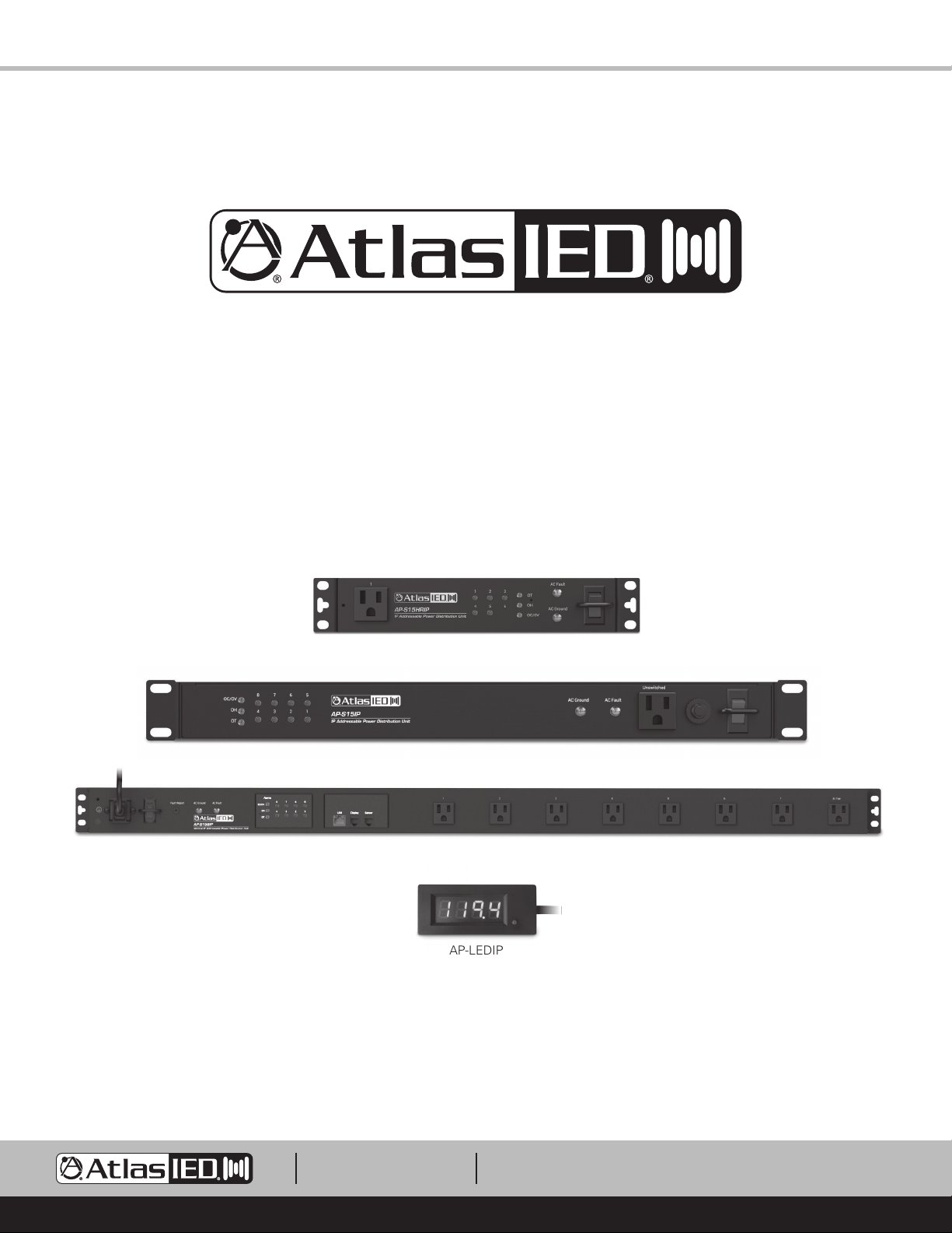
AP-S15HRIP
AP-S15IP
AP-S158IP
AP-LEDIP
1601 JACK MCKAY BLVD.
ENNIS, TEXAS 75119 U.S.A.
TELEPHONE: (800) 876-3333
[email protected]
– 1 –
AtlasIED.com
Page 2
AP-S15HRIP / AP-S15IP / AP-S158IP
Quick Start Guide
Introduction
Thank you for purchasing this AtlasIED IP power distribution system. This document is designed to provide a high-level overview of the IP power
distribution system product family including common features to all models. AtlasIED recommends visiting www.atlasied.com and downloading the full
manual for the model purchased. The AP-IP discovery software and other related guides for the AtlasIED AP-IP power distribution systems can also be
downloaded.
Note: AtlasIED requires that AP-IP power distribution systems be installed by a qualified electrician or IT technician. The manual must be read in
its entirety before starting the installation. The AtlasIED AP-IP power distribution systems meet the Californian law SB-327. Each unit has a unique
password assigned to it for logging into the device. The AP-S15HRIP is a LAN (Local Area Network) device and requires a secured firewall for network
operation. AtlasIED recommends consulting an IT specialist before installation.
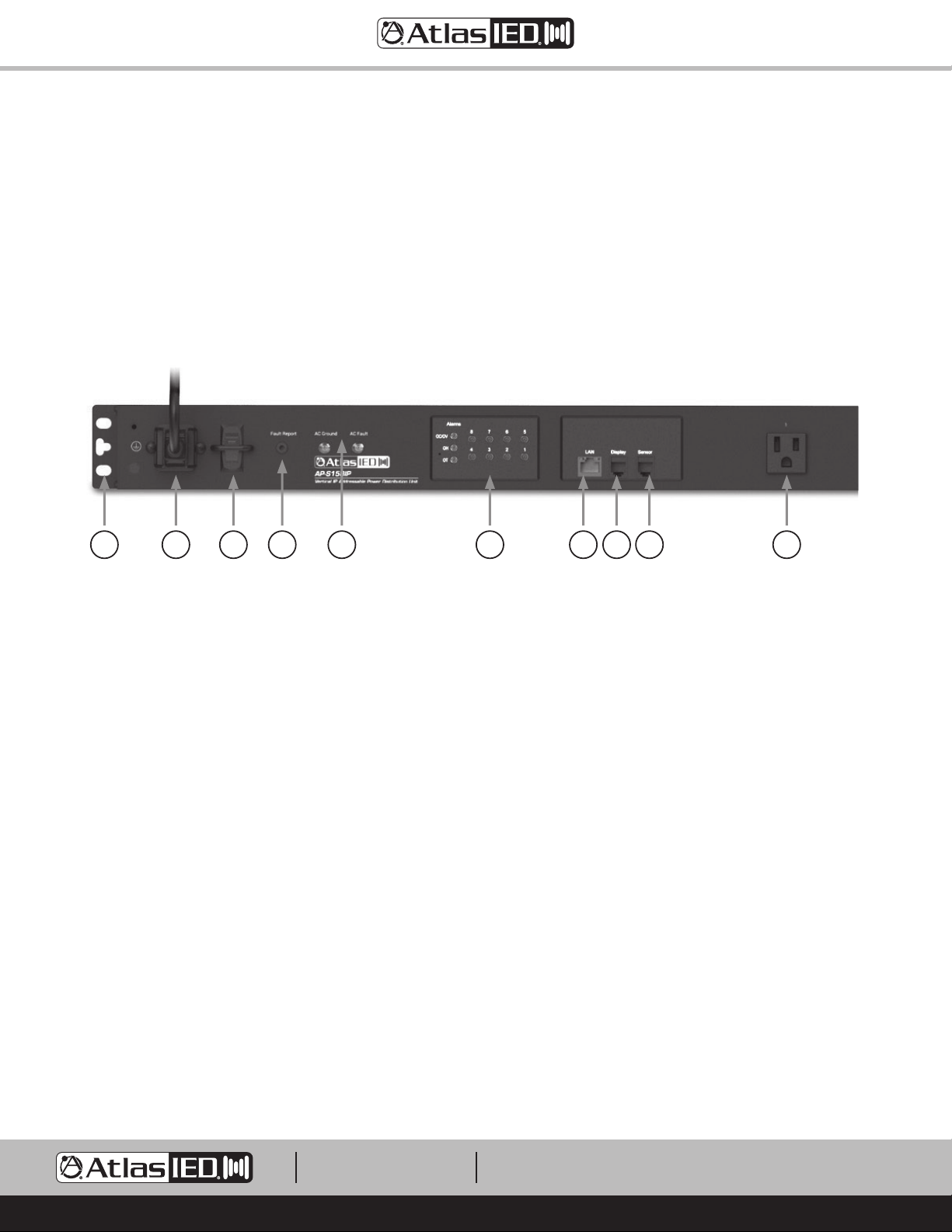
AP-S158IP Shown
1 5 6 9 102374 8
Unit Features and Installing the AP-IP Power Distribution System
1. Rack Mount Ears - Install the power strip rack ears (if applicable) and secure the unit in an equipment rack. Note: The AP-S15HRIP is shipped with
a rack mount kit so it can be rack mounted into an AtlasIED wall mount half rack or a 19" rack. It can be mounted alone or with any AtlasIED half
width products such as the DPA-102PM, PA40G / PA60G, or MA40G / MA60G in a 19" 1RU space. (Notes 2 & 3 on page 11)
2. Temperature / Humidity Probe Port - Install the temperature / humidity probe in the rear port marked “Sensor”. Note: The unit will not function
without the temperature probe installed. The front panel alarm LEDs will flash indicating the probe is not installed.
3. External Display Port - Install the remote LED data display into the rear port marked “Display”. Note: Installation is not required for operation. This
remote AP-LEDIP magnetic data display comes with a 10ft cable so it can be placed on the rack where data viewing is preferred. This display can
show AC mains voltage, current, rack temperature and humidity. The preferred data value to be shown can be set in the WEB interface. The other
readings can be accessed by pressing the data display viewing switch located on the front of the display. One of the main features is the display of
the IP address assigned to the power strip. Press and hold the data display viewing button and the assigned IP address will scroll.
4. Fault Cable - Install the fault report cable in the 3.5mm port marked “Fault Report”. The cable is a 2-conductor 3.5mm wire with bare ends allowing
it to interface with an external device that supports contact closure GPIO. The port is normally closed (NC) when the unit is active and opens when
the AC power goes off or if an alarm fault is detected such as voltage, current, temperature or humidity. Note: Installation is not required for
operation.
5. IEC Power Socket - Install the power cord and retainer clip.
6. Power Switch - When in the On position the switch will illuminate red.
7. Ethernet Cable - Install and connect to LAN (Local Area Network).
8. AC Ground Indicator - When the units power switch is On possition and the AC Ground indicator is illuminating red, it means the power strip
does not have a sufficient earth ground for safe operation. In some cases, we have found that use of a non-factory power cord can cause faults.
We recommend using the power cord that is shipped with the unit. If the factory power cord has been found to be working correctly and the
Ground Fault indicator is still illuminating, the AC mains outlet the power strip is plugged into does not have a sufficient earth ground. This AC
outlet should be checked by an electrician.
9. Status Indicators - Refer to the Alarm Indicators, Front Panel Switches and Turning On the Unit sections.
10. 120V AC Mains Outlet - If the outlet indicator is illuminated green, the outlet has AC power present.
1601 JACK MCKAY BLVD.
ENNIS, TEXAS 75119 U.S.A.
TELEPHONE: (800) 876-3333
[email protected]
– 2 –
AtlasIED.com
Page 3
AP-S15HRIP / AP-S15IP / AP-S158IP
Quick Start Guide
Opening the Carton
Each carton contains:
• AP-IP power distribution system
• Rack ears & screws (Except AP-S158IP)
• Power cord
• Power cord retainer clip & screws
• Temperature / humidity sensor probe
• Fault cable and a data display
Note: Do not plug the unit into an AC mains source until the following steps have been completed:
Connecting to an AC Mains Source
1. Installation must be done by a qualified electrician or IT technician.
2. Connect only to a 15A NEMA5-15 outlet. Any modification of the AC plug will void the warranty.
Alarm Indicators, Front Panel Switches, and Turning On the Unit
1. Ensure no equipment is connected to the power distribution system.
2. Place the power switch in the On / up position. The switch will illuminate red.
3. Both the AC Ground & AC Fault LEDs should be off. If either of these indicators are illuminated, stop the installation and refer to the manual.
4. Factory default on - The power distribution system is programmed from the factory to sequence on all the outlets from 1 to 5 or 8 depending on
the model. Each outlet has an associated indicator located on the front of the unit that is specific to the numbered AC outlet. These indicators will
illuminate green when the associated numbered AC outlet is active and will have AC volts present.
5. Individual AC outlet On / Off indicators can also turn an output on or off. Press the switch firmly to activate. Factory default is set so the switches
are active but can be disabled in the WEB Interface.
6. The AP-IP Power strips do not require a network to operate. It is needed for programing, remote monitoring, to run a scheduled sequence or to
execute the auto ping feature. Each outlet can be turned On / Off manually. The Over / Under Voltage, Over Current, Humidity Warning,
Temperature Warning, Remote Fan Colling and Spike / Surge protection work without a network connection.
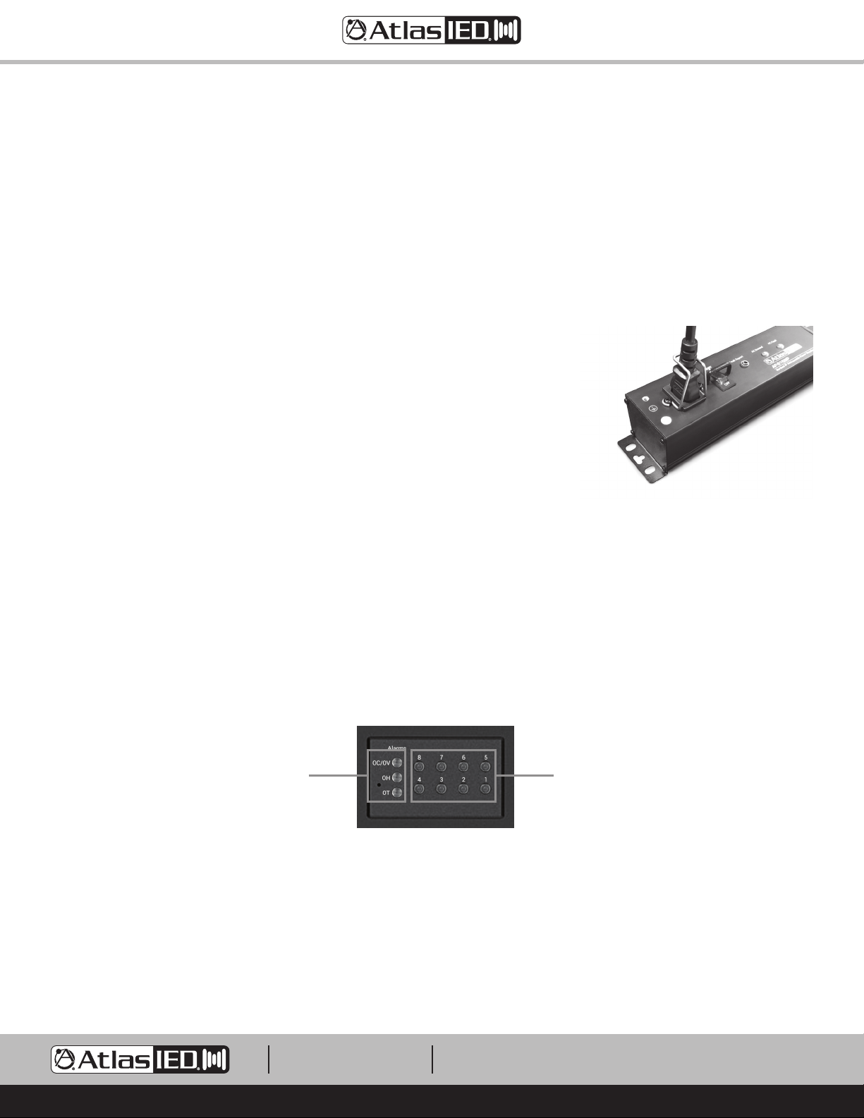
AP-S158IP Shown
Alarm LEDs will flash if
temp / humidity probe is
not plugged in
Individual outlet On / Off
switches
Accessing the Unit’s WEB User Interface
Each AtlasIED AP-IP power distribution system includes a unique set of features and configurations. Ethernet connectivity is not required for
basic operation, but to take full advantage of the settings such as alarms, sequence timing, and scheduling, the AP-IP power distribution system’s
control panel must be accessed via the LAN (Local Area Network) or local computer. External software is not required for operation. The software is
embedded in the power distribution system in what is called the Web browser GUI control panel interface. Follow the steps listed below to access the
onboard Web control panel.
1. All AtlasIED AP-IP power distribution systems ship (factory default) in DHCP mode.
2. Plug a Cat5/6 cable into the unit’s LAN Ethernet port and then into a router that is set to DHCP. The router will issue an IP address to the AP-IP
Power Strip. The assigned IP address is the specific location of the unit on the network. This address will allow access to the unit’s Web GUI
interface.
1601 JACK MCKAY BLVD.
ENNIS, TEXAS 75119 U.S.A.
TELEPHONE: (800) 876-3333
[email protected]
AtlasIED.com
– 3 –
Page 4
AP-S15HRIP / AP-S15IP / AP-S158IP
AP-S15HRIP
IP Addressable Power Distribution Unit
Switched
LAN
Display
Sensor
Fault Report 4 5 / Fan321
AC FaultAlarms
AC Ground
1
OT
OH
OC/OV
425
3
10.4"
(264.1mm)
Quick Start Guide
Finding the IP Address
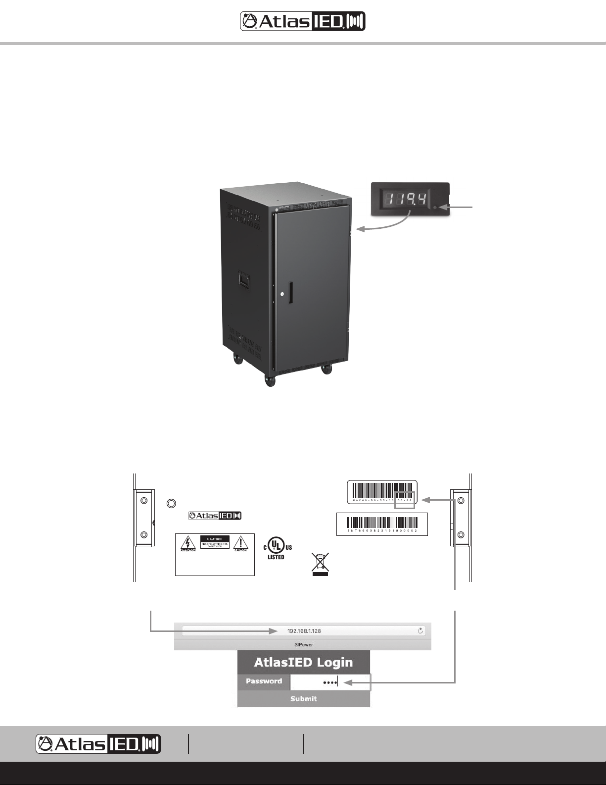
Using the AP-LEDIP external display is the fastest way to discover the IP Address. Plug the AP-LEDIP display into the AP-IP power distribution
system’s display port. Press and hold down the viewing selection button until the IP address starts to scroll across the display. An IP address example
would be 192.168.1.138. Write down the IP address number to enter it later into a Web browser. Note: IP Discovery software is also available at
www.atlasied.com. For specific IP address operation refer to the manual. Note: The LED display can show AC mains voltage, current, rack
temperature, rack humidity or the IP address. Press the button on the front of the display to cycle through the display modes to access the different
data screens.
Magnetic display can be placed
outside of the door when closed.
Press and hold the button to display
the IP Address. Press once to
change the display data.
Logging Into the Unit
To access the unit’s Web GUI, open a web browser like Google Chrome®, Microsoft® Edge® or Safari®. Each unit has a unique password assigned to
it. Enter the unit’s factory default password as show in the illustration below. The password is the last 4 digits of the MAC address. Find the MAC
address label on the chassis. Example: A MAC address looks like (40-D8-55-10-D0-66). Input D066 (No dash) as the password to access the unit.
Note: For “0” equals zero. Passwords can be changed in GUI.
1601 Jack McKay Blvd. • Ennis, TX 75119
800.876.3333 • AtlasIED.com
Model: AP-S15HRIP
WARNING: SHOCK HAZARD - DO NOT OPEN
AVIS: RISQUE DE CHOC ELÉCTRIQUE - NE PAS OUVRIR
WARNING: TO REDUCE THE RISK OF FIRE OR ELECTRIC SHOCK
DO NOT EXPOSE THIS EQUIPMENT TO RAIN OR MOISTURE
AVIS: NE PAS EXPOSER CE MATÉRIEL À LA PLUIE OU L’HUMIDITE
AFIN DE REDUIRE LE RISQUE D’INFLAMMATION OU DE CHOC ELÉCTRIQUE
I.T.E.
E467418
Made in Taiwan
Input: 120Vac 50/60Hz 12A
Output: 120Vac 50/60Hz 12A 1440W Maximum
Caution: The socket-outlet shall be installed near
the equipment and shall be easily accessible.ID: T
Last 4 Digits of MAC AddressUnit’s IP Address
1601 JACK MCKAY BLVD.
ENNIS, TEXAS 75119 U.S.A.
TELEPHONE: (800) 876-3333
[email protected]
– 4 –
AtlasIED.com
Page 5

AP-S15HRIP / AP-S15IP / AP-S158IP
Quick Start Guide
Web GUI User Interface
Page Selections
There are 5 pages to the AP-IP Power Strip WEB Interface: Status, Alarm Settings, Schedule Setting, Network Settings and Configuration settings.
Note: It is very important to select Save after each entry or configuration change or the information will not be applied.
• Status Page - The Status page is also the home landing page. Use this page to monitor the AC Mains Voltage, Current, Temperature, and Humidity,
as well as view alarm status. Each AC Outlet can be individually controlled to be On or Off, along with triggering a system On / Off sequence.
• Alarm Page - This device has multiple system alarms that can trigger a visual or mechanical alarm warning. Specific alarm settings can be set for
Temperature, Humidity, Current, and Over / Under AC Mains Voltage. Each alarm can be enabled or disabled. An alarm activity log shows the
history of when a alarm was activated.
• Scheduler Page - Each outlet can be set to be On or Off all of the time, or it can be assigned to a timed 24/7 schedule individually or as part of a
group sequence.
• Network Settings Page - This page allows for configuring DHCP or Static IP mode. Note: The unit is set to DHCP mode out of the box. Each
outlet has individual IP monitoring ability. Any network equipment that is connected to the same network can have an auto ping monitored for
operation. Each outlet can be configured to receive an auto ping test, and if no response is received from the monitored product, the associated
outlet will be rebooted. The unit’s password can be changed. A factory reset can also be performed.
• Configuration Page - On this page several unit settings can be configured such as customizing the units or individual outlet names, and assigning
an outlet to a grouped management. The front panel outlet On / Off switches can be disabled. Rack temperature can be monitored, and if needed,
a fan can be assigned to an outlet and configured to come on at specific temperature. The external LED display viewing can be configured.
Grouped Outlets Sequence On / Off Button
Temperature, Humidity,
Voltage, and Current
Readings
Alarm Status
Outlet On / Off Status
Important Programing Tips
1. On the left side of the GUI there are access buttons to the following pages: Status, Alarm, Scheduler, Network Settings and Configuration.
Navigate through each page to get familiar with it, then start programing.
2. Each page & section has a SAVE button. Don’t forget after each entry to select SAVE or the settings will not be applied.
3. Read all information notes on each page. This will be helpful understanding why certain features may be grayed out. Some features cannot be
assigned to multiple functions. Example: Outlet 8 for the AP-S15IP & AP-S158IP cannot be assigned to grouped sequence or to 24/7 schedule if
assigned to the fan feature.
4. It is important to refresh the Web browser to be assured current data is being viewed. Web browsers have a cash memory and need to be
refreshed to clear the cash memory and reload the data.
1601 JACK MCKAY BLVD.
ENNIS, TEXAS 75119 U.S.A.
TELEPHONE: (800) 876-3333
[email protected]
AtlasIED.com
– 5 –
Page 6
AP-S15HRIP / AP-S15IP / AP-S158IP
Quick Start Guide
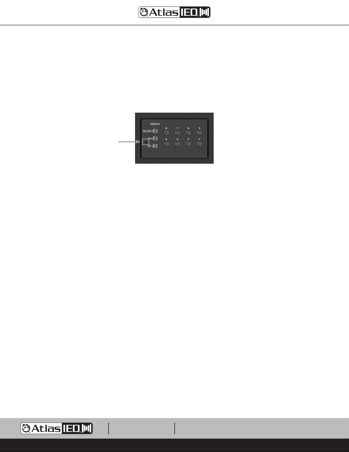
Factory Reset Switch
The Factory Reset switch is located in the front panel as indicated in the picture below. Insert a small object like a paper clip into the hole to access
the switch. Gently press and hold the switch inward for 3 seconds, then release. The unit’s outlets and display will shut off and turn back on indicating
the Factory Reset was successful. The Factory Reset switch will reset all functions that were previously programmed and will also reset the unit to
accept DHCP IP address. Note: Any custom passwords will be replaced by the last 4 digits of the MAC address. Refer to the section Logging Into the
Unit for details.
AP-S158IP Shown
Plugging Equipment Into An Outlet
After the unit has been installed in a rack, equipment can be connected to it. There are a few things to consider before starting. Note: The AtlasIED IP
power distribution systems must be installed by qualified technician. Before proceeding, visit atlasied.com to obtain an installation manual. Read the
manual entirely before proceeding with the installation of this product.
1. Total current draw of the power strip cannot exceed 12A continuous signal or 15A IT / Audio applications or the AC Mains 15A Breaker may trip.
Every product should have a current draw rating, add up all the equipment’s total current and make sure it doesn’t exceed 1440W.
Note: Pay special attention to audio amplifiers, they typically consume the most power compared to processors or controllers.
2. Audio amplifiers should turn on last, and off first in a sequence.
3. If a computer or router needs to be on all of the time, an outlet can be programmed to stay on for that operation.
Rack Mounting the AP-S15HRIP
A rack kit is included with the purchase of the AP-S15HRIP. The AP-S15HR width fits most rack cabinets that are classified as half-width. There are no
industry standards for these types of racks and rack widths may vary between manufactures. The AP-S15HRIP can be mounted into an AtlasIED wall
mount half-width rack or a 19” rack. The AP-S15HRIP can be mounted with any AtlasIED 1/2 RU products or mounted alone, but requires a rack mount
kit. For half rack designs there needs to be a minimum distance of 9.25" between rails. AtlasIED recommends checking the distance between the rack
rail opening before proceeding. Note: Two AP-S15HRIP units cannot be mounted side by side.
Kit Contains
• Qty 2 Rack ears
• Qty 8 M4 x 8mm Pan head rack ear screws
• Qty 1 Rack extension plate for single unit mounting
• Qty 2 M4 x 10mm pan head black screws to combine extension plate to rack ear
• Qty 2 M4 hex nuts for screws to secure screw to extension plate and rack ear
• Qty 2 Top joiner plates
3
• Qty 8 4-40 x
• Qty 1 Front panel joiner plate
• Qty 2 4-40 x
/8 flat head black screws to secure top joiner plate
3
/8 flat head black screws to secure front panel joiner plate
1601 JACK MCKAY BLVD.
ENNIS, TEXAS 75119 U.S.A.
TELEPHONE: (800) 876-3333
[email protected]
AtlasIED.com
– 6 –
Page 7
AP-S15HRIP / AP-S15IP / AP-S158IP
Quick Start Guide
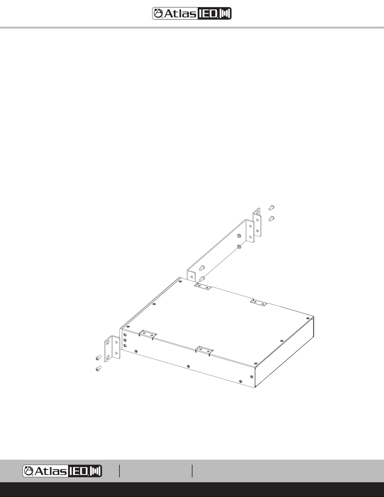
Configuration 1 - Mounting a Single 1 RU Model
1. Remove amplifier from electrical source.
2. Remove the four feet.
3. Align and secure the chassis extension plate to a rack mount ear with the enclosed screws and nuts.
4. Locate the two open holes on each side of the amp located towards the front panel.
5. Align the enclosed rack mount ear and extension assembly to the chassis holes located in step 4.
6. Use the enclosed chassis screws to attach the rack ears and extension assembly to the chassis. Secure firmly, do not over tighten. Repeat step
for opposite chassis side.
7. Disregard extra pieces.
8. Ready for rack installation. Note: It is important the amplifiers have the proper clearance around it for proper heat dissipation. Always allow at least
1.75" around the amplifier for to assure safe operation. Never mount an amplifier in an enclosed air tight rack. All racks must have air vents on all
sides or forced air cooling to assure proper heat dissipation.
M4 x 10mm Pan Head Screw
M4 x 8mm Pan Head Screw
M4 Hex Nut
M4 x 8mm Pan Head Screw
1601 JACK MCKAY BLVD.
ENNIS, TEXAS 75119 U.S.A.
TELEPHONE: (800) 876-3333
[email protected]
– 7 –
AtlasIED.com
Page 8

AP-S15HRIP / AP-S15IP / AP-S158IP
Quick Start Guide
Configuration 2 - Mounting 2 1RU Models
Note: Not all 1RU half rack models can be joined next to each other. The following combinations can be joined: ASP-MG2240, DPA102PM, MA40G,
MA60G, PA40G, PA60G, AP-S15HR, AP-S15RTHR, and AP-S15HRIP are interchangeable. Note: Two AP-S15HR units cannot be rack mounted together
side-by-side. Call AtlasIED for other models not listed.
1. Remove amplifier from electrical source.
2. Remove the four feet.
3. Align and secure two chassis joiner plates with the enclosed screws to the top of units. Note: Must install both plates, one towards the front and
one towards the back.
4. Locate the two open holes on each side of the amp located towards the front panel.
5. Align the enclosed rack mount ear to the chassis holes located in step 2.
6. Use the enclosed chassis screws to attach the rack ears to the chassis. Secure firmly, do not over tighten. Repeat step for opposite chassis side.
3
7. Install the front panel joiner plate using the two 4-40 x
is installed in the rack.
8. Disregard extra pieces.
9. Ready for rack installation. Note: It is important the amplifiers have the proper clearance around it for proper heat dissipation. Always allow at least
1.75" around the amplifier for to assure safe operation. Never mount an amplifier in an enclosed air tight rack. All racks must have air vents on all
sides or forced air cooling to assure proper heat dissipation.
/8 flat head black screws. Note: The front panel joiner plate can be removed after the unit
3
4-40 x
/8 Flat Head Screw
Note: Not all 1RU half rack models
can be joined next to each other.
Refer to the list above or call
AtlasIED Customer Service.
1601 JACK MCKAY BLVD.
ENNIS, TEXAS 75119 U.S.A.
TELEPHONE: (800) 876-3333
[email protected]
– 8 –
AtlasIED.com
Page 9

AP-S15HRIP / AP-S15IP / AP-S158IP
Quick Start Guide
Front Panel Joiner Plate
Not used on PA702 or PA1001G
4-40 x 3/8 Flat Head Screw
AP-S15HRIP System Diagram Example
1601 JACK MCKAY BLVD.
ENNIS, TEXAS 75119 U.S.A.
TELEPHONE: (800) 876-3333
[email protected]
– 9 –
AtlasIED.com
Page 10

AP-S15HRIP / AP-S15IP / AP-S158IP
Quick Start Guide
System
Type Networked AC Power Distribution Conditioner & Suppressor
Load Rating Max Load 15A (1800W), Rated Load 12A (1440W)
Network Type LAN, WEB User Interface (Note 1)
Panel
Activation Switch Rocker with Security Bar
Circuit Breaker 15A Resettable Power Switch
Outlet On / Off Switches Momentary Manual
AC Outlets
AC Mains IEC Power Socket IEC NEMA 5-15P 15A 1800W with Power Cord Retainer
LAN Port RJ45, Ethernet Port
Temp / Humidity Port RJ14, Temperature, Humidity Probe, 2M, Probe Included
Display Port RJ25, for AP-LEDIP Display for Voltage, Current, Temperature, Humidity, IP Address
Fault Report Port 3.5mm Jack, Fault Reporting Contact Closure, Normally Closed & Opens During Fault State, Cable Included
GPIO Fault Relay Port Fault Relay Interface, Temperature, Humidity, Over & Under Voltage, Over Current, Surge, Cable Included
Indicators
Power On Indicator Power Switch LED, Red
Outlet Status Indicators Green, Qty 8 (AP-S15HRIP Qty 5)
Over Temperature Alarm Indicator Red, Programmable Range 50° - 176°F , 10° - 80°C
Over Humidity Alarm Indicator Red, Programmable Range 15 - 95%
Over Current / Voltage Alarm Indicator Red, Programmable Range High - Voltage 100V - 140V, Under Voltage 80V- 120V
AC Fault Indicator Red, Illuminates When Surge Protection is Damaged
AC Ground Indicator Red, Illuminates When Earth Ground Is Bad
User Interface and Configuration
Web Interface HTTP Protocol, XML Commands Available
Status Voltage, Current, Temperature, Humidity, Spike Protection, Ground Fault, Outlet Status
Alarms Voltage Hi / Lo, Current, System Temperature, Humidity, Fault Log
Scheduler 24 / 7, Group Schedule or Individual Outlet Schedule
Network LAN Base, DHCP or Static IP, Individual Outlet Auto Ping Reset (Note 1)
Configuration Outlet Renaming, Group Assignment, Sequence Delay Timing, Temperature Activated Outlet
Technical Data
Max AC Mains Current 12A, 1440W
Operating Voltage 100VAC - 132VAC
Power Consumption 8-Watts
Noise Attenuation RFI 10dB @ 10kHz / 40dB @ 100kHz / 100dB @ 10MHz
Min. Spike Clamping Voltage 460VRMS @ 3000A
Max. Spike Clamping Voltage 6000V, 1 nanosecond
Spike Clamping Voltage @ 100A 1250Vp for 20µs
Maximum Surge Current 6,500A
Energy Rating @ 2ms 600 Joules
Unit Operating Temperature Range 40º - 105ºF, 5º - 40.5ºC
Humidity Range 5% to 95% Relative Humidity
Fault Reporting Web, GPIO Contact Closure (Closed During Normal Operation, Opens During Fault Condition), API-Commands
NEMA5-15R Switched (Programmable), Qty 8 (AP-S15HRIP Qty 5)
Note: Outlet 8 Can Be Used to Activate a Fan Triggered by Temperature Range of On: 51° - 176°F / Off: 50° - 175°F
1601 JACK MCKAY BLVD.
ENNIS, TEXAS 75119 U.S.A.
TELEPHONE: (800) 876-3333
[email protected]
– 10 –
AtlasIED.com
Page 11

AP-S15HRIP / AP-S15IP / AP-S158IP
Quick Start Guide
Mechanical
Chassis Finish Black
Product Dimensions (HxWxD)
Shipping Dimensions (HxWxD)
Unit Weight
Shipping Weight
Package Contents
Agency Approvals
Safety Listing North America UL60950-1, CAN/CSA C22.2 No. 60950-1, UL1449
Note 1: The AP-S15HRIP, AP-S15IP, and AP-S158IP meet the Californian law SB-327. Each unit is shipped with a unique password that can be changed
for accessing the device over the network. They are LAN (Local Area Network) devices and require a firewall or VPN for secure connection outside the
network operation. AtlasIED recommends consulting an IT specialist for best network security practices before installation.
Note 2: The AP-S15HRIP fits most rack cabinets that are classified as half-width. There are no industry standards for these types of racks and rack
widths may vary between manufactures. AtlasIED recommends checking the distance between the rack rail opening before proceeding.
Note 3: The AP-S15HRIP can be mounted into an AtlasIED wall mount half-width rack or a 19" rack. The AP-S15HRIP can be mounted with any
AtlasIED
1
/2 RU products or mounted alone, but requires a rack mount kit. Note: Two AP-S15HRIP units cannot be mounted side by side.
AP-S158IP - 2.24" x 40.5" x 3.33" (57mm x 1029mm x 85mm)
AP-S15IP - 1.75" x 19" x 7.35" (45mm x 481mm x 187mm)
AP-S15HRIP - 1.75" x 8.83" x 8" (45mm x 224mm x 204mm) - Width with Rack Ears 10.4" (267mm) (Note 2)
AP-S158IP - 6.25" x 42" x 5" (159mm x 1066mm x 127mm)
AP-S15IP - 5" x 18.7" x 10.6" (129mm x 475mm x 269mm)
AP-S15HRIP - 3.5" x 12.12" x 11.5" (90mm x 308mm x 290mm)
AP-S158IP - 3.6 lbs. (1.63kg)
AP-S15IP - 5.5 lbs. (2.5kg)
AP-S15HRIP - 3.5 lbs. (1.6kg)
AP-S158IP - 6 lbs. (2.7kg)
AP-S15IP - 7.72 lbs. (3.5kg)
AP-S15HRIP - 5.5 lbs. (2.5kg)
Temperature / Humidity Probe, Fault Interface Probe, 2m 14-Gauge IED Power Cord, IEC Power Cord Retailer Bracket,
AP-LEDIP Display, Qty 1 Each, Rack Mount Kit for
1
/2 Width & 19" Racks (Note 3)
1601 JACK MCKAY BLVD.
ENNIS, TEXAS 75119 U.S.A.
TELEPHONE: (800) 876-3333
[email protected]
– 11 –
AtlasIED.com
Page 12

AP-S15HRIP / AP-S15IP / AP-S158IP
Quick Start Guide
Limited Warranty
All products manufactured by AtlasIED are warranted to the original dealer/installer, industrial or commercial purchaser to be free from defects in
material and workmanship and to be in compliance with our published specifications, if any. This warranty shall extend from the date of purchase for
a period of three years on all AtlasIED products, including SOUNDOLIER brand, and ATLAS SOUND brand products except as follows: one year on
electronics and control systems; one year on replacement parts; and one year on Musician Series stands and related accessories. Additionally, fuses
and lamps carry no warranty. AtlasIED will solely at its discretion, replace at no charge or repair free of charge defective parts or products when the
product has been applied and used in accordance with our published operation and installation instructions. We will not be responsible for defects
caused by improper storage, misuse (including failure to provide reasonable and necessary maintenance), accident, abnormal atmospheres, water
immersion, lightning discharge, or malfunctions when products have been modified or operated in excess of rated power, altered, serviced or installed
in other than a workman like manner. The original sales invoice should be retained as evidence of purchase under the terms of this warranty. All
warranty returns must comply with our returns policy set forth below. When products returned to AtlasIED do not qualify for repair or replacement
under our warranty, repairs may be performed at prevailing costs for material and labor unless there is included with the returned product(s) a written
request for an estimate of repair costs before any nonwarranty work is performed. In the event of replacement or upon completion of repairs, return
shipment will be made with the transportation charges collect.
EXCEPT TO THE EXTENT THAT APPLICABLE LAW PREVENTS THE LIMITATION OF CONSEQUENTIAL DAMAGES FOR PERSONAL INJURY, ATLASIED
SHALL NOT BE LIABLE IN TORT OR CONTRACT FOR ANY DIRECT, CONSEQUENTIAL OR INCIDENTAL LOSS OR DAMAGE ARISING OUT OF THE
INSTALLATION, USE OR INABILITY TO USE THE PRODUCTS. THE ABOVE WARRANTY IS IN LIEU OF ALL OTHER WARRANTIES INCLUDING BUT
NOT LIMITED TO WARRANTIES OF MERCHANTABILITY AND FITNESS FOR A PARTICULAR PURPOSE.
AtlasIED does not assume, or does it authorize any other person to assume or extend on its behalf, any other warranty, obligation, or liability. This
warranty gives you specific legal rights and you may have other rights which vary from state to state.
Service
Should your AP-IP Power Distribution System require service, please contact the AtlasIED warranty department at
1-877-689-8055, ext. 277 or atlasied.com/support to obtain an RA number.
AtlasIED Tech Support can be reached at 1-800-876-3333 or atlasied.com/support
Visit our website at www.AtlasIED.com to see other Atlas products.
©2020 Atlas Sound L.P. The Atlas “Circle A”, Soundolier, and Atlas Sound are trademarks of Atlas Sound L.P. IED is a registered trademark of Innovative Electronic Designs LLC. All Rights Reserved.
All other trademarks are the property of their respective owners. All specs are subject to change without notice. ATS006007 RevD 4/20
1601 JACK MCKAY BLVD.
ENNIS, TEXAS 75119 U.S.A.
TELEPHONE: (800) 876-3333
[email protected]
AtlasIED.com
– 12 –
 Loading...