

Page 1
Owner’s Manual
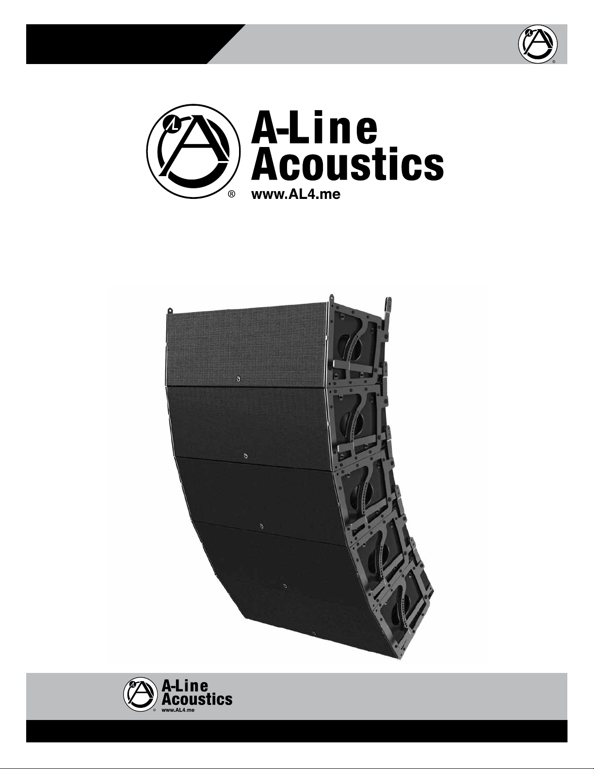
AL123A-B
Line Array System with EZAL Rigging
AL123A-B
Line Array System with EZAL Rigging
1601 Jack McKay Blvd. • Ennis, Texas 75119 U.S.A.
Telephone: 800.876.3333 • Fax: 800.765.3435
– 1 – AtlasSound.com
Specifications are subject to change without notice.
Page 2

AL123A-B
Owner’s Manual
Line Array System with EZAL Rigging
Table of Contents
Important Safety Instructions ................................................................................................................. 3
Applications ............................................................................................................................................ 6
Overview ................................................................................................................................................. 6
EZAL Rigging System Patent # 7261180 ............................................................................................... 6
Rear Panel .............................................................................................................................................. 7
Features ................................................................................................................................................. 7
Adjustment .............................................................................................................................................. 8
Adjusting the Cabinets ............................................................................................................................ 9
Focusing the Array ................................................................................................................................... 9
Accessories ............................................................................................................................................. 9
DSP and Network Settings .....................................................................................................................11
Display Control ...................................................................................................................................... 16
Specifications .........................................................................................................................................17
Warranty ................................................................................................................................................ 18
1601 Jack McKay Blvd. • Ennis, Texas 75119 U.S.A.
Telephone: 800.876.3333 • Fax: 800.765.3435
AtlasSound.com – 2 –
Specifications are subject to change without notice.
Page 3
Owner’s Manual
AL123A-B
Line Array System with EZAL Rigging
Important Safety Instructions
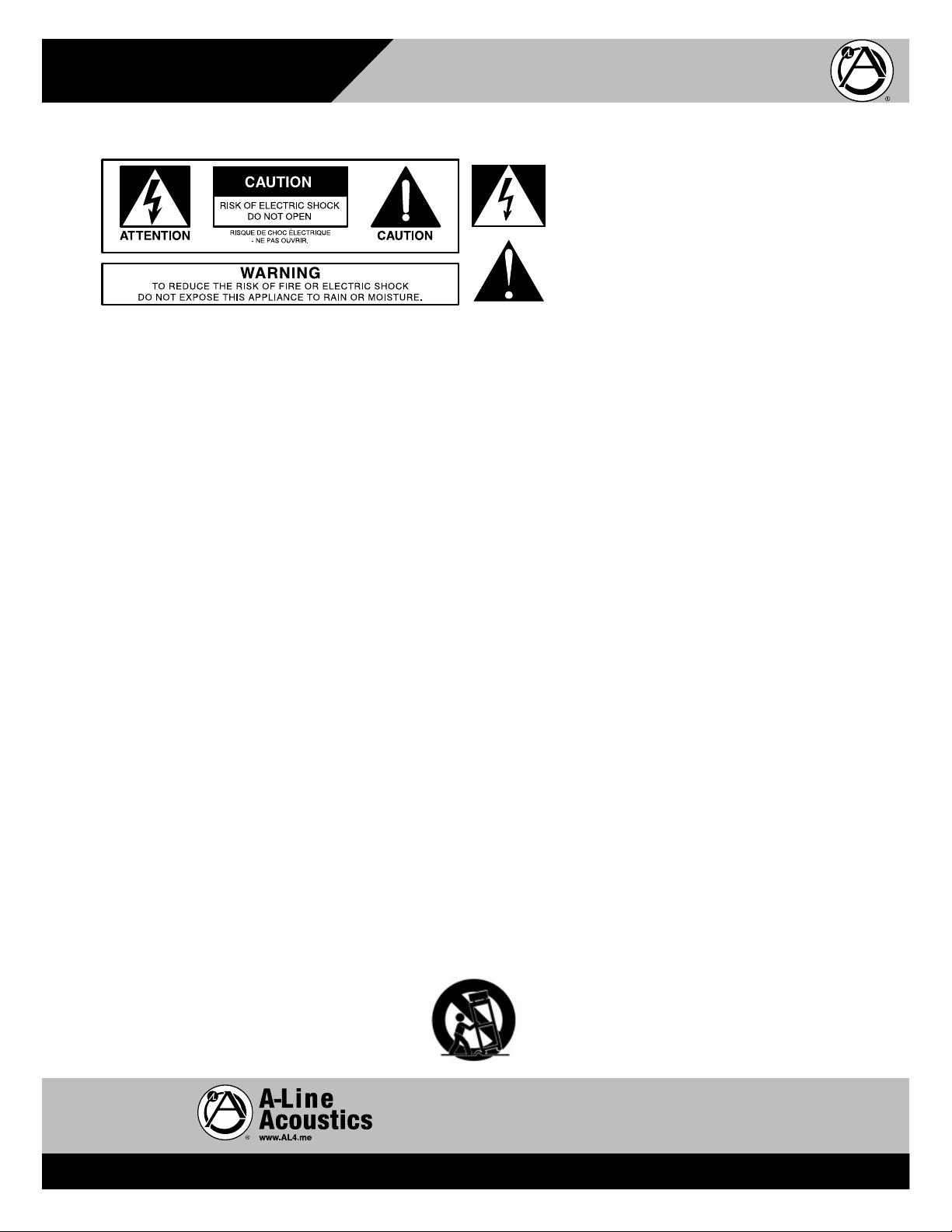
The lightning flash with arrowhead symbol within an
equilateral triangle, is intended to alert the user to the
presence of uninsulated “dangerous voltage “ within the
product’s enclosure that may be of sufficient magnitude
to constitute a risk of electric shock to persons.
The exclamation point within an equilateral triangle is
intended to alert the user to the presence of important
operating and maintenance (servicing) instructions in the
literature accompanying the product.
1. Read these instructions.
2. Keep these instructions.
3. Heed all warnings.
4. Follow all instructions.
5. Do not use this device near water.
6. Clean only with dry cloth.
7. Do not block any ventilation openings. Install in accordance with the manufacturer’s instructions.
8. Do not install near any heat sources such as radiators, heat registers, stoves, or other device that produce heat.
9. Do not defeat the safety purpose of the polarized or grounding-type plug. A polarized plug has two blades with one wider than the
other. A grounding type plug has two blades and a third grounding prong. The wide blade or the third prong are provided for your
safety. If the provided plug does not fit into your outlet, consult an electrician for replacement of the obsolete outlet.
10. Protect the power cord from being walked on or pinched particularly at plugs, convenience receptacles, and the point where they
exit from the device.
11. Only use attachments/accessories specified by the manufacturer.
12 This product requires the power cable to be a three conductor, connected to a PowerCON™ end.
13. Unplug this device during lightning storms or when unused for long periods of time.
14. Refer all servicing to qualified service personnel. Servicing is required when the device has been damaged in any way, such as
power-supply cord or plug is damaged, liquid has been spilled, or objects have fallen into the device, the device has been exposed
to rain or moisture, does not operate normally, or has been dropped.
15. WARNING: To reduce the risk of fire or electric shock, this device should not be exposed to rain or moisture and objects filled with
liquids, such as a vase, should not be placed on this device.
16. The PowerCON™ power output should not be used to daisy chain cabinets. To ensure correct operation, only run 1 cabinet off of a
15 to 20 amp circuit.
1601 Jack McKay Blvd. • Ennis, Texas 75119 U.S.A.
Telephone: 800.876.3333 • Fax: 800.765.3435
– 3 – AtlasSound.com
Specifications are subject to change without notice.
Page 4
AL123A-B
Line Array System with EZAL Rigging
Owner’s Manual
When The Device Is In Use
• To prevent electric shock, do not remove the product cover as there are high voltage components inside. Refer all servicing to
Atlas Sound.
• Should any of the following irregularities occur during use, immediately switch off the power, disconnect the power cord from the
AC outlet and contact Atlas Sound. Do not to attempt to continue operation with the product as this may cause fire or electric shock:
• Smoke or strange smell coming from the unit.
• If the product falls or the case is damaged.
• If water or any metallic objects falls into the product.
• If the power supply cord is damaged in any way.
• If the unit is malfunctioning.
• Do not insert or drop metallic objects or flammable materials into the ventilation holes of the product's cover, as this may result in
electric shock or fire.
• Do not place any containers with liquid or metallic objects on the top of the product. If any liquid spills into the unit, fire or electric
shock may result.
• Never operate this product or touch the power supply cord during an electrical storm, electric shock may result.
• Never exceed the power rating on the product when connecting equipment. Fire and/or property damage may result.
• Operate the product only with the voltage specified on the unit. Fire and/or electric shock may result if a higher voltage is used.
• Do not modify, kink, or cut the power cord. Do not place the power cord in close proximity to heaters and do not place heavy objects
on the power cord, including the product itself, doing so may result in fire or electrical shock.
• Ensure that the safety ground terminal is connected to a proper ground. Never connect the ground to a gas pipe as a catastrophic
disaster may result.
• Be sure the installation of the product is stable, avoid slanted surfaces as the product may fall and cause injury or property damage.
When Installing The Product
• Always make sure your system is set up on a level surface and will not fall over.
• Always assure power is Off to amplifiers before making any connections. Assure that all electrical equipment is properly grounded.
WARNING
CAUTION
1601 Jack McKay Blvd. • Ennis, Texas 75119 U.S.A.
Telephone: 800.876.3333 • Fax: 800.765.3435
AtlasSound.com – 4 –
Specifications are subject to change without notice.
Page 5

Owner’s Manual
AL123A-B
Line Array System with EZAL Rigging
When The Product Is In Use
• Never place heavy objects on the product, causing it to fall and/or break, resulting in personal injury and property damage. In
addition, the product itself may fall and cause injury and property damage.
• Contact Atlas Sound for instructions on cleaning the inside of the unit. Large accumulations of dust inside the unit may result in heat
buildup and fire.
• Ensure that the power supply plug is securely plugged into the wall outlet. Never allow dust to accumulate on the power plug or
inside the wall outlet.
• When cleaning the unit or the unit is not to be operated for an extended period, unplug the power cord from the wall.
• Hearing Damage - CAUTION: All professional loudspeaker systems are capable of generating very high sound pressure levels. Use
care with placement and operation to avoid exposure to excessive levels that can cause permanent hearing damage.
• Suspension & Mounting - Suspension or “flying” speaker systems requires training and expertise. Improper rigging of a flying
speaker may result in injury, death, equipment damage, and legal liability. Installation must be carried out by fully qualified installers,
in accordance with all required safety codes and standards at the place of installation. A 5:1 design factor is a generally accepted
minimum standard. However, legal requirements for overhead suspension vary by municipality, please consult your local safety
standards office before installing any product. We also recommend that you thoroughly check any laws and bylaws prior to
installation. Loudspeakers flown in theaters, nightclubs, conference centers, or other places of work and entertainment must be
provided with an independent, correctly rated and securely attached secondary safety, in addition to the principle suspension
point(s). This secondary safety must prevent the loudspeaker from dropping more than (6") should the principle suspension
device fail. If you lack the skills, training, and proper ancillary equipment to fly a speaker system, do not attempt to do
so. For additional information regarding the suspension of loudspeakers or to purchase rigging materials, please contact our friends
at Adaptive Technologies Group,1635 E. Burnett St. Signal Hills, CA 90755. www.adapttechgroup.com Telephone (562) 424-1100 and
CAUTION
Fax (562) 424-3520
1601 Jack McKay Blvd. • Ennis, Texas 75119 U.S.A.
Telephone: 800.876.3333 • Fax: 800.765.3435
– 5 – AtlasSound.com
Specifications are subject to change without notice.
Page 6

AL123A-B
Owner’s Manual
Line Array System with EZAL Rigging
Applications
The AL123A-B large format line array system is designed for both fixed and touring professional audio installation applications where
clarity of speech and music are most important. The patented EZAL rigging included with the system enables quick and easy setup and
tear down from truck to stage in touring applications as the angle of the array can be adjusted on the fly.
• Corporate Speaking Events
• Live Music
• Sporting Arenas
• Large Indoor or Outdoor Facilities
• Ballrooms, Auditoriums, House of Worship
Overview
The AL123A-B is a single line array 3-way speaker enclosure that is designed to be either flown or ground stacked using four or more
units in a vertical array. The system includes dual 12" woofers, four 6" midrange drivers, and dual 1.4" high frequency compression
drivers powered by an integrated 3600-watt amplifier. A nominal horizontal coverage pattern of 120 degree is maintained, while the
vertical coverage will vary depending on the number of enclosures used and the splay angles that are chosen by using Atlas A-Line
patented EZAL rigging system. The pattern control will also depend on the length of the array. The integrated amplifier includes on-board
DSP that can be adjusted in real time via a network connection. The AL123A-B DSP is factory preset for flat response. Additional
adjustments can be made based on the number of units being used and the nature of the venue where they are used.
EZAL Rigging System - US Patent #7,261,180
The patented EZAL Rigging System is a precision engineered rigging system that is capable of precisely adjusting angles between
adjacent cabinets by up to 5 degrees while under load. The system can be ground stacked up to six cabinets or flown up to twelve
cabinets. Extreme caution and care by trained technicians is a requirement for successfully using this system. Only supplied
accessories and pins should be used with this rigging system. All pins should be fully inserted through the rigging and locked into place.
Check for proper seating of the pins by tugging and turning each pin after seating to ensure that the ball locking mechanism is fully
expanded on the backside of the rigging. The pins and rigging should be double checked by another member of the crew before the
system is raised. In all instances where this system is flown from a structure, the technician responsible for the hanging points should
be ETCP certified. For more information regarding ETCP certification visit http://etcp.plasa.org/cert_technicians/riggers.html.
1601 Jack McKay Blvd. • Ennis, Texas 75119 U.S.A.
Telephone: 800.876.3333 • Fax: 800.765.3435
AtlasSound.com – 6 –
Specifications are subject to change without notice.
Page 7

Owner’s Manual
AL123A-B
Line Array System with EZAL Rigging
Rear Panel
MAINS, OUTPUT
15A, 90-230VAC
60HZ
MAINS, INPUT
15A, 90-230VAC
60HZ
FUSE
TYPE 3AG
15A, 250VAC
CAUTION
RISK OF ELECTRIC SHOCK
DO NOT OPEN
WARNING
TO REDUCE THE RISK OF FIRE OR ELECTRIC
SHOCK DO NOT EXPOSE THIS EQUIPMENT TO
RAIN OR MOISTURE
PGM PORT
Features
• Onboard Internal Class “D” Amplification Modules with On Board Networkable DSP
• 2 x 12" Woofers / 4 x 6.5" Midrange Speakers / 2 x 1.4" Compression Drivers on a Proprietary LSR Line Source Replicator
• Baltic Birch Plywood Construction
• Network Controlled DSP Programing
• Universal Power Supply with Auto Selection, 85-268V, 50-60Hz
• EZAL Multi Angle Patented Rigging System Calibrated in Precision Increments
CLIP
LIMIT
-3
-6
-15
MODEL: AL123A-B
SERIAL
Made in U.S.A.
ENCODER
WHEEL
AUDIO OUT
Shield PIN 1
+ PIN 2
-PIN 3
AUDIO IN
NETWORK
RJ45
10/100
1601 Jack McKay Blvd. • Ennis, Texas 75119 U.S.A.
Telephone: 800.876.3333 • Fax: 800.765.3435
– 7 – AtlasSound.com
Specifications are subject to change without notice.
Page 8

AL123A-B
Owner’s Manual
Line Array System with EZAL Rigging
Adjustment
The EZAL Rigging System adjustment arrangements are illustrated below. Before operating the mechanism, it is essential to carefully
study and thoroughly understand each drawing. The drawing illustrates the degree increments for the lever handle located on the left
and right side of the cabinet and the rear cabinet adjustments. The lever arm adjustment located on the side of the cabinet is most
commonly used. The rear cabinet adjustment is rarely used. This adjustment is typically only used on the bottom one or two cabinets of
an array.
Lever Handle
Adjustment #
1 0° 4.7°
2 0.4° 5°
3 0.8° 5.47°
4 1.25° 5.85°
5 1.7° 6.25°
6 2.15° 6.67°
7 2.7° 7.2°
8 3.25° 7.7°
9 3.82° 8.25°
10 4.4° 8.85°
11 5° 9.42°
12 5.6° 10°
Rear Cabinet
Adjustment Hole A
Rear Cabinet
Adjustment Hole B
Handle
Lever
1
2
3
4
5
6
7
8
9
10
11
12
Handle
Lever
1
2
A
B
Handle
Lever
1
2
A
B
Handle
Lever
0.0°
4.7°
1601 Jack McKay Blvd. • Ennis, Texas 75119 U.S.A.
Telephone: 800.876.3333 • Fax: 800.765.3435
AtlasSound.com – 8 –
Specifications are subject to change without notice.
Page 9

Owner’s Manual
AL123A-B
Line Array System with EZAL Rigging
Adjusting Cabinets
Holding the lever handle securely, remove the pin from the lever handle at the holes from 0 degrees to 5 degrees. Be sure to remove the
pin on both sides of the cabinet. Move the lever handle to change the curve of the array. Reinsert the pins at desired angle and double
check for proper seating.
Focusing the Array
When focusing the array try to keep the array as straight as possible with the least amount of curve. Fly the array at a height at which
the main section of the array is directed at the farthest point needed to cover. If the coverage pattern is directed just above the front
listeners, the greatest energy will be directed to the farthest listeners and coverage from front to back will be uniform.
Fly the array only in those instances where site lines are obstructed by the array or vertical coverage requires the height. Using a curve
1
⁄2 to 1 degree per cabinet will be sufficient. Flying short arrays (4 to 6 cabinets) high is generally not recommended. In general,
of
more cabinets will be needed (approximately 3 to 6 more per array) to cover near seating in an array that is flown at about 20 feet to
the bottom cabinet. The short array can behave in many ways like its longer counterpart if height is kept to a minimum and the amount
of curve is limited. However, there is no substitute for a longer array; the longer the array the greater the sound at a distance. The
longer the array, the lower the low frequency that the array has pattern control over. Short arrays are point sources at low frequencies.
Generally, short arrays of 4 - 6 cabinets will not have any curve in outdoor venues where you are trying to maximize distance. Indoors,
in a ballroom, club or small theatre where you may need to fly the array, angling the bottom box down will usually achieve the desired
down front coverage.
Accessories
Wheelboard
The wheel board is designed to hold up to four (4) AL123A-B cabinets at one time. The wheel board can be used as a platform for
playing the speakers in installations where flying the speakers is not required. The cabinets can be curved or tilted slightly forward on
the wheel board to change the projection angle if necessary. The included stabilizer bars must be used to support the speakers and
wheel board when speakers are angled.
Stacking the cabinets on the wheel board:
1. At least two people are required to stack AL123A-B cabinets on the wheel board.
2. Engage the wheel locks on all four casters first to ensure the wheel board will remain stationary.
3. Prepare the first cabinet to be stacked on the wheel board with at least one person on each side facing each other and
supporting the cabinet by the side handles.
4. Lift and place the AL123A-B cabinet on the wheel board. Attach the front pins first, and then align the bottom back mounting
part of the rigging with the raised slots on the wheel board. Insert the pins so the cabinet is locked on to the wheel board.
5. Repeat this process for other cabinets to be stacked keeping in mind that a maximum of four (4) total cabinets can be stacked
on the wheel board.
1601 Jack McKay Blvd. • Ennis, Texas 75119 U.S.A.
Telephone: 800.876.3333 • Fax: 800.765.3435
– 9 – AtlasSound.com
Specifications are subject to change without notice.
Page 10

AL123A-B
Owner’s Manual
Line Array System with EZAL Rigging
Using the Stabilizer bars:
1. Pull the retaining handles up to remove the stabilizer bars. The bar has a lock hole on its side for easy shipping.
2. Put the stabilizer bar into the sleeve and adjust the bar to 1 of the 8 positions.
3. Each stabilizer bar has leveling leg to ensure stability. The leveling leg can also be used to give the cabinets a slight forward
angle. Do not increase the angle that the leveling leg can provide with blocks or other supports as the wheel board and
speakers can tip over resulting in damage or injury.
The cabinets can also be curved to the desired curve angle using the integrated EZAL rigging.
Attaching the Cabinet to the Fly Frame
The large fly frame is designed to be the structural interface between and AL123A-B and the venue structure where the array is to be
flown or suspended. It is best to use four points located close to the four corners to suspend the array. Attach the array to the fly frame
with the four push button pins provided with the array. It is easier to attach the two front fly points before connecting the two rear fly
points since the rear bracket can be moved to help engage the pins.
The maximum load capacity of the fly frame is 2000 lbs. and therefore no more than 12 AL123A-B cabinets can be suspended from
a single fly frame. If an AL218A-B subwoofer is incorporated into the array, one of the AL123A-B cabinets will have to be removed
from the array to account for the weight of the AL218A-B. For example, if two (2) AL218A-B units are used in the array, only ten (10)
AL123A-B cabinets can be used in the same array. Up to six (6) AL218A-B and five (5) AL123A-B units can be attached to the same fly
frame.
The integrated EZAL rigging can be used to attach the cabinet to the fly frame. Align the EZAL rigging points on the top of the cabinet
to the front and middle holes on the fly frame. Connect the securing pins through the rigging points and holes ensuring they lock in
place. Connect remaining speakers to the bottom of the first using the EZAL rigging points.
1601 Jack McKay Blvd. • Ennis, Texas 75119 U.S.A.
Telephone: 800.876.3333 • Fax: 800.765.3435
AtlasSound.com – 10 –
Specifications are subject to change without notice.
Page 11

Owner’s Manual
AL123A-B
Line Array System with EZAL Rigging
DSP and Network Settings
The Atlas A-Line AL123A-B speaker contains a powerful network DSP control. Each amplified enclosure can be assigned a name,
grouped together, or tuned with a custom EQ, time delay, or custom limiting for any application.
General Operation Setup and Configuration
1. Install the latest version of the Atlas A-Line Acoustics AllDSP software that matches the users computer operating system. Options
are available for Windows
2. Once the software is installed, open the Atlas A-Line Acoustics AllDSP software.
3. When the program opens the user will see
a. If connected using either the USB or RJ45 network connection, the AL123A-B array element will be listed in this window. If
connected through the network the display will also show the IP address. Network controls and set-up will be covered in the
section labeled “Network Settings”.
4. Launch the control window for the enclosure by clicking [>>]. This will open the control for the selected enclosure. Any number of
units can be grouped. This will be covered in the section labeled “group controls”.
5. The control window will open and it may take a few seconds to synchronize with the AllDSP software.
6. The system will then be logged into the user mode. In this mode the user can save and load presets. Note: Presets 1 thru 6 are
locked by the factory. Presets 7 through 80 are available for use. A preset can contain a custom EQ or gain setting for an enclosure.
In the User mode the default password is “Password”. The password can be changed allowing the User to lock the enclosure
controls so no adjustments can be made.
7. Admin mode can also be accessed. Click “hardware-> Enter password” then type the password “A_Line”. The user can also change
this password if required. Admin mode will allow control of “IN1” through the RJ45 network or USB connection. Custom presets
can also be saved in this mode. “IN1” and “IN2” are linked, and only “IN1” can be adjusted.
Network Settings
When one or more AL123A-B units are connected to the network through the RJ45 connection, the Atlas A-Line AllDSP will recognize and
show each connected enclosure. The units can be connected to the network via a standard router and/or network switch. The IP settings
will be assigned automatically by DHCP if your network supports this capability. The AL123A-B units will assign their own IP addresses if
no DHCP server is found. Alternatively, a fixed IP address and subnet mask can be set. If the connected computer is not hardwired to the
network but connected via Wi-Fi, the A-Line AllDSP will still recognize the connected AL123A-B units.
Updating Firmware and Factory Files
The Atlas A-Line AllDSP software may undergo continual development to increase features and controls. Check the Atlas website,
atlassound.com, or contact a local Atlas Sound representative to obtain updated software and factory file data. The factory file contains
all manufacture settings for the AL123A-B.
CAUTION- when performing an update on the AL123A-B, DO NOT apply any signal through the unit until the update is completed and
the AL123A-B factory file is loaded. If the unit is updated and the factory file is not updated damage to the unit will occur.
Interface Update
1. Open The A-Line AllDSP software.
2. Check for connected AL123A-B units that need to be updated.
®
32 and 64bit versions as well as Apple®.
1601 Jack McKay Blvd. • Ennis, Texas 75119 U.S.A.
Telephone: 800.876.3333 • Fax: 800.765.3435
– 11 – AtlasSound.com
Specifications are subject to change without notice.
Page 12

AL123A-B
Line Array System with EZAL Rigging
3. Select “Enable update” on the main control window.
4. A column will then show a [>>] if an update is needed for the selected AL123A-B unit.
Owner’s Manual
5. Click the [>>}; the update process will begin. Wait until the process is completed. Do not unplug or disconnect the AL123A-B unit
from the network.
a. If the process fails, try again.
b. When the process is completed a success notice window will open. At this point the user can move to the next step
Firmware Update
1. After the Interface has updated, open the main control window. Next select “Update firmware” from the drop down menu to
update the Firmware
a. After selecting “Update firmware” the system will prompt the user to back up the presets and to reload them after the update.
Backup the presets to avoid loss of any custom created settings.
2. The system will go through its update process. After it has finished updating it will ask to load the factory file. Select the latest
factory file, downloadable from AtlasSound.com.
3. Allow the system to update the factory file information.
4. Cycle the power and the system will be completely updated and ready for use.
AL123A-B System Controls
Group Controls
Any number of units can be put in a group. While in this group the unit gain and any EQ settings on the IN1 are all grouped together. If
1 unit is changed, all associated units in the group will change together.
Multiple Groups are possible and can be given Custom Names
Create a new group by clicking “Tools” and select “New Group”. A new window will open allowing assignment of a name to the group.
Select the group name in the drop down box for one of the connected units. The groups will then be subdivided below the listed online
units.
1601 Jack McKay Blvd. • Ennis, Texas 75119 U.S.A.
Telephone: 800.876.3333 • Fax: 800.765.3435
AtlasSound.com – 12 –
Specifications are subject to change without notice.
Page 13

Owner’s Manual
AL123A-B
Line Array System with EZAL Rigging
Unit Name Change
The unit names can be changed. This is useful when grouping and or using multiple units together. It is an easy way to know which
enclosure is being controlled. The display on the back of each enclosure will illustrate the name assigned to it. This name will stay
loaded even after power cycling. The name is only removed when updating firmware and/or if changed by the user.
User Control
The default control when loading the control screen is “User mode”. In this mode the user can load and change presets, group units,
update firmware, open presets, and change gain settings for each unit. The User also has authority to change the user password to lock
the unit. The default password is “Password”.
When locking the unit the display controls are also locked. This can also be achieved from the Display. The User also can adjust IN EQ,
limiter, and delay settings from the Display. This is described in more detail in the ”Display Control” section of the manual.
Admin Control
Admin control gives the end user more access to the network controls. The Admin control is accessible by password. The default
password is: “A_Line” Selecting “hardware” and then entering the password allows the user to access this control. The password can
be changed at the user’s discretion.
The Admin control has the ability to modify the EQ and gain/limiter settings on each of the networked units. If the unit that is being
controlled is within a group, all grouped units will change to the same setting. Please note when adjusting the EQ or limiting that
drastic EQ changes can reduce the headroom and capability of the AL123A-B system.
Within the Admin control the user can lock the unit and choose what options they would like available when locked. It is suggested
when locking the unit to not allow any setting changes and prevent unauthorized tampering. This can be accomplished by clicking
->Hardware>Configure>Access Rights>Locked Access Rights. A window will then show what settings are available. Select the check
boxes for the settings to be accessible when locked.
AL123A-B Settings
Power on Preset - The user can define a custom preset to load when the unit is powered On.
Auto Power Down - The user can specify a time delay before the unit goes into standby mode when no signal is present. A value of “0”
will disable the Auto Power shutoff.
Display - The user can turn the display Off or dim the display. There is also a time delay setting for turning the display Off.
Note: the display will awaken if the controls on the back of the enclosure are used.
Presets
The user can specify, modify, and save presets as needed. Presets 1 thru 6 are locked by the factory for future functionality. Presets 7
thru 80 are available for the user and can be named by the user.
Saving a preset
1. Make any adjustments necessary
2. Create a name for the preset and type it into the Preset text box.
3. Select a Preset slot to save the preset.
4. Click “Store”. It will take a few seconds to save the preset. The preset will now be saved in the unit memory.
Create Preset file to load on multiple units
1. Start with saving a preset as described above.
2. Click “Store”
3. Save the file.
4. Load the file on a different AL123A-B unit
5. Click “Store” on the bottom preset tab.
1601 Jack McKay Blvd. • Ennis, Texas 75119 U.S.A.
Telephone: 800.876.3333 • Fax: 800.765.3435
– 13 – AtlasSound.com
Specifications are subject to change without notice.
Page 14

AL123A-B
Owner’s Manual
Line Array System with EZAL Rigging
Preset Back Up
1. Click file and select back up presets.
2. Choose location to back up presets.
3. Select Restore presets to restore saved presets. An error message display if presets one thru six are selected as they are
locked. The user can skip these presets.
Grouped Presets
If multiple AL123A-B units are grouped, presets save together. Each grouped AL123A-B unit will be adjusted if one of the presets are
saved/loaded.
IN1 –IN2 Settings
The IN1 and IN2 are linked together and the user can adjust only IN1. When in the Admin mode the EQ can be adjusted through the network.
The 10 band parametric EQ plus a general low pass and a general high pass can be adjusted. The user can also change the system time
delay, adjust limiter, and adjust the compressor. Each of the 10 filters has a drop down menu that allows the selection of different types
of adjustable filters.
1601 Jack McKay Blvd. • Ennis, Texas 75119 U.S.A.
Telephone: 800.876.3333 • Fax: 800.765.3435
AtlasSound.com – 14 –
Specifications are subject to change without notice.
Page 15

Owner’s Manual
AL123A-B
Line Array System with EZAL Rigging
Filters Available
1. Bell
2. Notch
3. All Pass
4. Low Shelf
5. High Shelf
6. Band Pass
7. High Pass
8. Low Pass
The user can select the frequency, gain, and Q for each of these filters. Also available are general High Pass and Low Pass filters shown
in. All of the filters can be turned On or Off using the check box.
The graph can be expanded or changed to show filter text info. A picture capturing the graph can also be saved. The filters can be
dragged to the desired setting. Any of these settings can be saved using the presets for later use. If the user will be using their own
equalization, note that over filtering/boosting frequencies can damage and reduce the effectiveness of this high-powered amplified unit.
Care will need to be taken to set the system up correctly.
1601 Jack McKay Blvd. • Ennis, Texas 75119 U.S.A.
Telephone: 800.876.3333 • Fax: 800.765.3435
– 15 – AtlasSound.com
Specifications are subject to change without notice.
Page 16

AL123A-B
Owner’s Manual
Line Array System with EZAL Rigging
Display Control
The system can be controlled with the rear display. The rear display can also display information about the unit’s status and operation.
The following can be adjusted through the rear display.
1. Gain
2. EQ (10 band parametric EQ as described in the EQ section)
3. HP/LP
4. Delay
5. Limiter
6. Compressor
General Control
The encoder wheel will allow the user to select and change the DSP settings. The wheel also serves as a button, pushing it selects the
selected option. If the user wants to back out of that selection the bottom left button can be pushed.
Menu Options Through Top Left Button (number).
1. Load Presets
2. Save Presets
3. Lock/Unlock
4. Version information
Rotate the encoder wheel to the desired preset or selection. Press the encoder wheel to select the desired preset or menu selection.
Confirm the choice by selecting Yes or No. Turn the encoder wheel to select and press the encoder wheel to enter.
Encoder Menu Options
Push the encoder and the display will activate.
IN2 <- Gain
0 dB
Pushing the encoder wheel a second time will point the arrow to the gain. At this time turning the encoder wheel will scroll through
the different PEQ, Limiter, Delay, Compressor and Gain settings. Push the encoder wheel to change any of these settings. The settings
associated with the user selection can then be changed.
PEQ settings example
1. Turn encoder to PEQ1-10.
2. Push encoder to enter the selected PEQ
3. The frequency setting will show first. Rotate the enclosure to the desired frequency in Hz. Push the encoder to enter the
selected frequency.
4. The display will then show the Gain setting. Rotate the encoder to the desired gain setting. Push the encoder to select the
displayed Gain setting.
5. The display will then show Q. Rotate the encoder to the desired Q setting. Push the encoder to select the displayed Q setting.
6. The display will next show Type. This selects the type of filter. Rotate the encoder to the desired filter type. Push the encoder to
select the displayed filter setting.
If at any time the user would like to back out of a setting the bottom left button will move back a menu selection each time it is
pressed.
1601 Jack McKay Blvd. • Ennis, Texas 75119 U.S.A.
Telephone: 800.876.3333 • Fax: 800.765.3435
AtlasSound.com – 16 –
Specifications are subject to change without notice.
Page 17

Owner’s Manual
Line Array System with EZAL Rigging
Specifications
Line Array AL123A-B
LF Driver Power (Watts) 2000
MR Driver Power (Watts) 800
HR Driver Power (Watts) 400
Drivers Two (2) 12" Low Frequency
Four (4) 6" Midrange
Two (2) 1.4" High Frequency
Frequency Response 70Hz - 18kHz
Connectors I/O PowerCON™ and M & F XLR
Height 13.9" (353.06mm)
Width 45.3" (1,150.62cm)
Depth 16.3" (414.02cm)
Weight 133 lbs. (60.33kg)
AL123A-B
1601 Jack McKay Blvd. • Ennis, Texas 75119 U.S.A.
Telephone: 800.876.3333 • Fax: 800.765.3435
– 17 – AtlasSound.com
Specifications are subject to change without notice.
Page 18

Notes:
AL123A-B
Owner’s Manual
Line Array System with EZAL Rigging
1601 Jack McKay Blvd. • Ennis, Texas 75119 U.S.A.
Telephone: 800.876.3333 • Fax: 800.765.3435
AtlasSound.com – 18 –
Specifications are subject to change without notice.
Page 19

Owner’s Manual
AL123A-B
Line Array System with EZAL Rigging
1601 Jack McKay Blvd. • Ennis, Texas 75119 U.S.A.
Telephone: 800.876.3333 • Fax: 800.765.3435
– 19 – AtlasSound.com
Specifications are subject to change without notice.
Page 20

AL123A-B
Owner’s Manual
Line Array System with EZAL Rigging
Limited Warranty
All products manufactured by Atlas A-Line Acoustics are warranted to the original dealer/installer, industrial or commercial purchaser
to be free from defects in material and workmanship and to be in compliance with our published specifications, if any. This warranty
shall extend from the date of purchase for a period of three years on all Atlas Sound products, including SOUNDOLIER brand, and
ATLAS SOUND brand products except as follows: one year on electronics and control systems; one year on replacement parts;
and one year on Musician Series stands and related accessories. Additionally, fuses and lamps carry no warranty. Atlas Sound will
solely at its discretion, replace at no charge or repair free of charge defective parts or products when the product has been applied
and used in accordance with our published operation and installation instructions. We will not be responsible for defects caused by
improper storage, misuse (including failure to provide reasonable and necessary maintenance), accident, abnormal atmospheres, water
immersion, lightning discharge, or malfunctions when products have been modified or operated in excess of rated power, altered,
serviced or installed in other than a workman like manner. The original sales invoice should be retained as evidence of purchase under
the terms of this warranty. All warranty returns must comply with our returns policy set forth below. When products returned to Atlas
Sound do not qualify for repair or replacement under our warranty, repairs may be performed at prevailing costs for material and labor
unless there is included with the returned product(s) a written request for an estimate of repair costs before any nonwarranty work is
performed. In the event of replacement or upon completion of repairs, return shipment will be made with the transportation charges
collect.
EXCEPT TO THE EXTENT THAT APPLICABLE LAW PREVENTS THE LIMITATION OF CONSEQUENTIAL DAMAGES FOR PERSONAL
INJURY, ATLAS SOUND SHALL NOT BE LIABLE IN TORT OR CONTRACT FOR ANY DIRECT, CONSEQUENTIAL OR INCIDENTAL LOSS
OR DAMAGE ARISING OUT OF THE INSTALLATION, USE OR INABILITY TO USE THE PRODUCTS. THE ABOVE WARRANTY IS IN
LIEU OF ALL OTHER WARRANTIES INCLUDING BUT NOT LIMITED TO WARRANTIES OF MERCHANTABILITY AND FITNESS FOR A
PARTICULAR PURPOSE.
Atlas Sound does not assume, or does it authorize any other person to assume or extend on its behalf, any other warranty, obligation,
or liability. This warranty gives you specific legal rights and you may have other rights which vary from state to state.
Service
Should your AL123A-B require service, please contact the Atlas A-Line Acoustics warranty department at
1-877-689-8055, ext. 277 to obtain an RA number.
Atlas A-Line Acoustics Tech Support can be reached at 1-800-876-3333.
Visit our website at www.al4.me to see other Atlas A-Line Acoustics products.
©2014 Atlas Sound L.P. All rights reserved. Atlas Sound and Atlas A-Line Acoustics are trademarks of Atlas Sound L.P.
All other trademarks are the property of their respective owners. ALA004806 RevA 3/14 • 21A10159 • AW0014674
1601 Jack McKay Blvd. • Ennis, Texas 75119 U.S.A.
Telephone: 800.876.3333 • Fax: 800.765.3435
AtlasSound.com – 20 –
Specifications are subject to change without notice.
 Loading...