

Page 1

AH Series Loudspeakers
8", 12", and 15"
1/11
8" - AH99-8ST, AH94-8ST, and AH66-8ST
15" - AH5040S, AH9040S, and AH6565S
12" - AH99-12ST, AH94-12ST, and AH66-12ST
©2012 Atlas Sound L.P. All rights reserved. Atlas Sound is a trademark of Atlas Sound L.P. All other trademarks are the property of their respective owners. All specs are subject to change without notice. ATS004338 RevA 5/12
High-Performance, Constant Directivity, 8", 12", And 15",
Two-Way, Indoor/Outdoor Loudspeaker Systems
1601 JACK MCKAY BLVD.
ENNIS, TEXAS 75119 U.S.A.
TELEPHONE: (800) 876-3333
FAX (800) 765-3435
AtlasSound.com
Page 2

2/11
AH Series Loudspeakers
8", 12", and 15"
Safety Instructions
Please Read Carefully Before Installing or Operating
• Read all instructions carefully
• Heed all warnings
• Assure that the speaker is securely mounted
Hearing Damage
CAUTION: These professional loudspeaker systems are capable of generating very high sound pressure levels. Use care with placement and
operation to avoid exposure to excessive levels that can cause permanent hearing damage.
Suspension & Mounting
Suspension or "flying" speaker systems requires training and expertise. Improper rigging of a flying speaker may result in injury, death, equipment
damage, and legal liability. Installation must be carried out by fully qualified installers, in accordance with all required safety codes and standards at the
place of installation.
A 5:1 design factor is a generally accepted minimum standard. However, legal requirements for overhead suspension vary by municipality,
please consult your local safety standards office before installing any product. We also recommend that you thoroughly check any laws and
bylaws prior to installation.
Loudspeakers flown in theaters, nightclubs, conference centers, or other places of work and entertainment must be provided with an independent,
correctly rated and securely attached secondary safety — in addition to the principle suspension point(s). This secondary safety must prevent the
loudspeaker from dropping more than (6") should the principle suspension device fail. If you lack the skills, training, and proper ancillary equipment to
fly a speaker system, do not attempt to do so.
For additional information regarding the suspension of loudspeakers or to purchase rigging materials, please contact our friends at
Allen Products, Inc.,1635 E. Burnett St. Signal Hills, CA 90755.
www.allenproducts.com
Telephone (562) 424-1100 and Fax (562) 424-3520
• Always assure power is OFF to amplifiers before making any connections
• Assure that all electrical equipment is properly grounded
• Keep instructions for future reference
• Should any questions arise after reading this document, please call Atlas Sound Tech Support at 800-876-3333
©2012 Atlas Sound L.P. All rights reserved. Atlas Sound is a trademark of Atlas Sound L.P. All other trademarks are the property of their respective owners. All specs are subject to change without notice. ATS004338 RevA 5/12
1601 JACK MCKAY BLVD.
ENNIS, TEXAS 75119 U.S.A.
TELEPHONE: (800) 876-3333
FAX (800) 765-3435
AtlasSound.com
Page 3
AH Series Loudspeakers
8", 12", and 15"
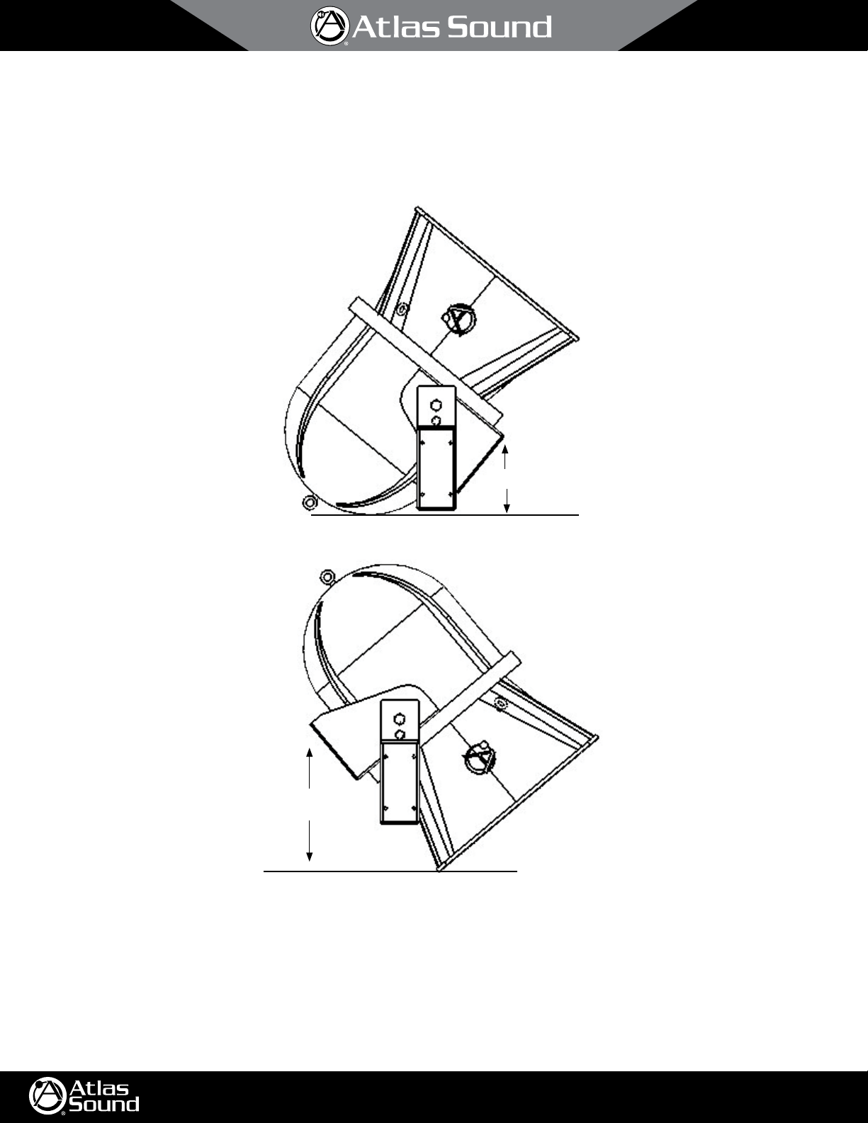
Assure that the AH speaker can be mounted in a manner that the sound pattern will be directed in the desired direction without any physical
interference. Note that the AH speaker mounting bracket allows the speaker to be tilted in excess of 50° in either direction. See illustration
below.
3/11
50˚
50˚
Weep-holes (for drainage) (AH5040S, AH9040S, and AH6565S 15" models only) are located on the same side as the input connectors. If the speaker is
tilted above parallel to the ground, the speaker should be installed with the weep holes down for water drainage.
©2012 Atlas Sound L.P. All rights reserved. Atlas Sound is a trademark of Atlas Sound L.P. All other trademarks are the property of their respective owners. All specs are subject to change without notice. ATS004338 RevA 5/12
1601 JACK MCKAY BLVD.
ENNIS, TEXAS 75119 U.S.A.
TELEPHONE: (800) 876-3333
FAX (800) 765-3435
AtlasSound.com
Page 4

4/11
AH Series Loudspeakers
8", 12", and 15"
Installation Via Mounting Bracket (Included)
General considerations and hardware recommendations
CAUTION: AH series models weigh as much as 81 pounds (36.7kg) – model AH5040CD. A fall from almost any height could result in serious
injury or death. Assure that the speaker is firmly mounted to an object that can handle the weight of the AH speaker. Remember that wind will add
considerable torque to the point of attachment. The mounting surface the AH speaker is being attached to should be able to handle five or more times
the weight of the AH speaker (7x recommended for locations subject to high wind forces).
Whenever the loudspeaker is mounted to a surface using the bracket, the installer must ensure that the surface is capable of safely and securely
supporting the load. The hardware employed must be safely and securely attached both to the loudspeaker and the surface in question, using only the
mounting holes. A general rule for soft surface installations (wood beams) is to multiply the corresponding working load limit by 75%; the result will
be an approximate working load strength.
Use thread locking compound for all installations.
CAUTION: Mount the speaker such that the shear force is at a right angle to the mounting bolts, and close to the connection, as shown:
SHEAR FORCE
TENSION FORCE
Lock Washer
Flat Washer
When mounting the AH speaker to a solid surface use the proper bolts, washers, and lock washers (Grade 5 minimum). Do not substitute mismatched
bolts and washers.
The AH speaker may be mounted to a pole or scoreboard. For such mounting, contact the light pole or scoreboard manufacturer for proper
instructions. If mounting to another surface, such as a beam, see the diagram on page seven for mounting hole locations. When in doubt contact a
qualified structural/mechanical engineer for approval of the mounting materials and methods.
©2012 Atlas Sound L.P. All rights reserved. Atlas Sound is a trademark of Atlas Sound L.P. All other trademarks are the property of their respective owners. All specs are subject to change without notice. ATS004338 RevA 5/12
1601 JACK MCKAY BLVD.
ENNIS, TEXAS 75119 U.S.A.
TELEPHONE: (800) 876-3333
FAX (800) 765-3435
AtlasSound.com
Page 5

AH Series Loudspeakers
8", 12", and 15"
Mounting
CAUTION: Mounting the AH loudspeaker requires two people, unless it is possible to safely clamp the speaker in position for alignment before mounting.
The bracket may be removed from the speaker for installation convenience. When re-attaching speaker to bracket be sure to tightly secure speaker
mounting bolts. Thread locking compound should also be used in this operation.
5
1. Choose the bracket mounting holes best suited for the surface you are mounting to. For best stability the
slots are recommended.
1
2. When using these mounting holes
use thread- locking compound on all parts.
3. Use the dimensions noted on the illustration to mark the points where the starting hole should be drilled.
4. Choose appropriately sized bit and drill holes.
5. Attach speaker bracket, using bolt, flat washer, and lock washer as shown and re-attach loudspeaker to bracket.
6. Secondary (safety) suspension point: Use a load rated cable or steel chain (capable of holding the speaker should it come loose from the
primary mounting point). This cable or chain assembly should be attached to at least (two) of the drop forge eyebolts provided on the AH
speaker and secured to the mounting surface via approved, load rated hardware.
⁄2" (grade 5 hardware minimum) hardware should be used with proper flat and lock washers. Remember to
⁄8" (16mm) diameter outer keyhole
5/11
(A)
(C)
(B)
(E)
©2012 Atlas Sound L.P. All rights reserved. Atlas Sound is a trademark of Atlas Sound L.P. All other trademarks are the property of their respective owners. All specs are subject to change without notice. ATS004338 RevA 5/12
BOTTOM VIEW
(D)
A B C D E
8" 4.25" 8.75" 2.75" 12.13" 15"
12" 5" 8.75" 2.75" 12.13" 18"
15" 5" 8.75" 2.75" 12.13" 18"
1601 JACK MCKAY BLVD.
ENNIS, TEXAS 75119 U.S.A.
TELEPHONE: (800) 876-3333
FAX (800) 765-3435
AtlasSound.com
Page 6

AH Series Loudspeakers
8", 12", and 15"
Suspended Installation Via Eyebolts (Included)
Using 1⁄4" Diameter Wire Rope
6/11
1
Note: Use of
fly point. 1⁄8" cable is not recommended as load limits are reduced to 400 lbs (181kg) static 250 lbs (113kg) moving per flying point.
Considerations for overhead suspension using AH Series eyebolts and wire rope:
1. Always apply the load to the eye in the plane of the eye.
2. Always use shoulder eyebolts for angular lifts.
3. Always tighten eyebolts securely against the load.
4. Apply first load to test the assembly. This load should be of equal or greater weight than the loads expected in use.
5. Use wire rope compression fittings & thimbles whenever possible and prepare terminations only as instructed by the manufacturer.
6. If wire rope clips are used, check and retighten to the manufacturer's recommended torque.
⁄4" load rated wire rope is suggested to provide a static working load limit of 1400 lbs (635kg) / moving load limit of 875 lbs (397kg) per
90˚
Eyebolt Working Load Limits
1
⁄4" Shank (Provided with AH Series)
90˚ angle: 650 lb (295 kg)
60˚ angle: 420 lb (191kg)
45˚ angle: 195 lb (88kg)
Less than 45˚ angle: 160 lb (73kg)
60˚
45˚
LESS THAN
45 DEGREE
ANGLE
0 ANGLE
©2012 Atlas Sound L.P. All rights reserved. Atlas Sound is a trademark of Atlas Sound L.P. All other trademarks are the property of their respective owners. All specs are subject to change without notice. ATS004338 RevA 5/12
1601 JACK MCKAY BLVD.
ENNIS, TEXAS 75119 U.S.A.
TELEPHONE: (800) 876-3333
FAX (800) 765-3435
AtlasSound.com
Page 7

7/11
AH Series Loudspeakers
8", 12", and 15"
Speaker Cable Recommendations And Connection Instructions
Wire Gauges (8Ω operation)
For very short distance speaker cable runs (less than 25') 16-gauge, stranded, twisted pair speaker cable may be used. For speaker cable runs
between 25' and 75', 14-gauge, stranded, twisted pair speaker cable is recommended. For speaker cable runs greater than 75', 12-gauge, stranded,
twisted pair speaker cable is necessary. For runs exceeding 150', please contact tech support for proper wire gauge or other installation solution using
the Atlas Sound AF140 autoformer.
15" models AH5040S, AH9040S, and AH6565S input connections are provided on a convenient recessed terminal block located on the bottom of the
loudspeaker. This terminal block includes a clear weather resistant cover which should be re-installed after terminating the speaker cabling to prevent
corrosion in outdoor applications.
8" & 12" models include a built-in, high efficiency 60 Watt 70.7V transformer. 7.5, 15, 30, and 60 Watt taps are available on a convenient recessed
terminal block located on the bottom of the loudspeaker. A removable jumper and additional pole on the terminal block is included for 8Ω direct
coupled operation. This terminal block includes a clear weather resistant cover which should be re-installed after terminating the speaker cabling to
prevent corrosion in outdoor applications.
Allow an adequate service loop for this connection to allow tilt of the loudspeaker. The speaker should be installed angled slightly down for proper
water drainage — in outdoor installations.
Access Holes For Speak-On
Screw Terminal Connectors
Hole For Strain Relief
8" & 12"
15"
©2012 Atlas Sound L.P. All rights reserved. Atlas Sound is a trademark of Atlas Sound L.P. All other trademarks are the property of their respective owners. All specs are subject to change without notice. ATS004338 RevA 5/12
1601 JACK MCKAY BLVD.
ENNIS, TEXAS 75119 U.S.A.
TELEPHONE: (800) 876-3333
FAX (800) 765-3435
AtlasSound.com
Page 8

8/11
AH Series Loudspeakers
8", 12", and 15"
Amplifier Considerations
Consult your amplifier owner’s manual to confirm power output at the rated impedance.
15" models: AH5040S, AH9040S, and AH6565S and other models used in 8Ω configuration. Each model exhibits an 8Ω (nominal) impedance.
(x2) AH models paralleled will present a 4Ω load to the amplifier.
(x3) AH models paralleled will present a 2.66Ω load to the amplifier.
(x4) AH models paralleled will present a 2Ω load to the amplifier.
ATLAS SOUND speaker system specifications list RMS power handling.
As a reference peak power = RMS x 1.414.
These ratings should be considered in selecting the best amplifier to power the speaker system.
For general use, amplifier output should match or exceed the RMS rated power of the speaker system: (250 Watts for the 15" AH models, 200 Watts
for the 12" models and 100 Watts for 8" models). For increased headroom and dynamic reproduction, the amplifier’s output should match or exceed
the peak power rating of the speaker system (354 Watts for the 15" AH models, 283 Watts for 12" models and 141 Watts for 8" models). In situations
where experienced professionals are operating the speaker system with proper limiting and frequency control devices inserted into the signal path
and adjusted properly, amplifier output may meet, but should not exceed 2x the RMS power rating of the speaker system (500 Watts for the 15" AH
models, 400 Watts for 12" AH models, and 200 Watts for 8" AH models). Utilizing the Atlas Sound model CP700 power amplifier will allow you to
easily match required power ratings for lmost any installation. Visit www.AtlasSound.com for more details on this product.
©2012 Atlas Sound L.P. All rights reserved. Atlas Sound is a trademark of Atlas Sound L.P. All other trademarks are the property of their respective owners. All specs are subject to change without notice. ATS004338 RevA 5/12
1601 JACK MCKAY BLVD.
ENNIS, TEXAS 75119 U.S.A.
TELEPHONE: (800) 876-3333
FAX (800) 765-3435
AtlasSound.com
Page 9

AH Series Loudspeakers
8", 12", and 15"
Specifications
8" Models Power Rating Frequency
AH99-8ST 100 Watts 90Hz to 10kHz 121dB 101dB 90˚ H
Res. ±5dB
AH94-8ST 100 Watts 90Hz to 10kHz 121dB 101dB 90˚ H
AH66-8ST 100 Watts 90Hz to 10kHz 120dB 100dB 65˚ H
12" Models Power Rating Frequency
AH99-12ST 200 Watts 80Hz to 10kHz 126dB 103dB 90˚ H
Res. ±5Db
AH94-12ST 200 Watts 80Hz to 10kHz 126dB 103dB 90˚ H
AH66-12ST 200 Watts 80Hz to 10kHz 125dB 102dB 65˚ H
Sound Level Dispersion Impedance Xfmr Taps Dimensions Weight
RP/1M 1W/1M
90˚ V
40˚ V
65˚ V
Sound Level Dispersion Impedance Xfmr Taps Dimensions Weight
RP/1M 1W/1M
90˚ V
40˚ V
65˚ V
8Ω Nominal 3.8, 7.5, 15,
30, and 60
Watts
8Ω Nominal 3.8, 7.5, 15,
30, and 60
Watts
8Ω Nominal 3.8, 7.5, 15,
30, and 60
Watts
8Ω Nominal 3.8, 7.5, 15,
30, and 60
Watts
8Ω Nominal 3.8, 7.5, 15,
30, and 60
Watts
8Ω Nominal 3.8, 7.5, 15,
30, and 60
Watts
23.86" (606mm) D
21.41" (544mm) W
21.25" (540mm) H
21.83" (554mm) D
19.66" (499mm) W
18.41" (468mm) H
20.91" (531mm) D
17.91" (455mm) W
19.66" (499mm) H
25.65" (652mm) D
22.06" (560mm) W
21.25" (540mm) H
25.65" (652mm) D
22.06" (560mm) W
21.25" (540mm) H
23.86" (606mm) D
21.41" (544mm) W
21.25" (540mm) H
9/11
65 lbs
(24.5 kg)
63 lbs
(28.6 kg)
61 lbs
(27.7 kg)
87 lbs
(39.5 kg)
85 lbs
(38.6 kg)
82 lbs
(37.2 kg)
15" Models Power Rating Frequency
Res. ±5Db
AH5040S 250 Watts 75Hz to 14.5kHz 127dB 104dB 50˚ H
AH6565S 250 Watts 75Hz to 14.5kHz 126dB 102dB 65˚ H
AH9040S 250 Watts 75Hz to 14.5kHz 126.5dB 102.5dB 90˚ H
Sound Level Dispersion Impedance Dimensions Weight
RP/1M 1W/1M
40˚ V
65˚ V
40˚ V
8Ω Nominal 20.5" (521mm) D
20.5" (521mm) W
32" (813mm) H
8Ω Nominal 20.5" (521mm) D
20.5" (521mm) W
32" (813mm) H
8Ω Nominal 22.5" (572mm) D
30" (762mm) W
31" (787mm) H
87 lbs
(39.5 kg)
87 lbs
(89.5 kg)
100 lbs
(45.4 kg)
Troubleshooting
PROBLEM POSSIBLE CAUSE REMEDY
There is no sound Power off. Equipment setting is wrong.
Low sound level Setting/volume control is set too low.
Sound cuts in and out System overload/oscillation intermittent
Distortion at increased levels Amplifier/speaker overdriven. Check that power to speaker isn't over limits. Check that amplifier isn't overdriven.
Speaker makes "buzzing"
noise
Volume set too low.
Loose connection. Check system from start to finish for crossed wires, loose connection, etc. On the AH
Connection is shorted or bad.
connection.
Hardware loose or speaker damaged. Make sure speaker grille is tight. Check other hardware connections. Check speakers
Assure that power is applied to all equipment in system. Check that routing (input/
output) controls are set correctly. Check that volume level is above minimum.
location check for correct connection.
Check volume levels or amplifiers and related equipment (equalizer). Check that
connections aren't partially shorted/corroded.
Check for overload condition or bad connection.
Reduce power to amplifier slightly.
for loose parts or speaker damage.
Call Atlas Sound tech support at 1-800-876-3333 with any additional questions.
©2012 Atlas Sound L.P. All rights reserved. Atlas Sound is a trademark of Atlas Sound L.P. All other trademarks are the property of their respective owners. All specs are subject to change without notice. ATS004338 RevA 5/12
1601 JACK MCKAY BLVD.
ENNIS, TEXAS 75119 U.S.A.
TELEPHONE: (800) 876-3333
FAX (800) 765-3435
AtlasSound.com
Page 10

™
Polestar
Uni.Frame - Galvanized
OUTDOOR SPEAKER MOUNTING SYSTEM
The UniFrame is a complete
mounting solution for outdoor
loudspeakers. Its design combines the
attributes of the PoleStar stainless “a-la-
carte” version into just two models produced
in steel and then galvanized to an outdoor
weather rating.
The UniFrame reduces the amount of parts required for the job
site and saves installation time by combining the support arm
and the pole adapter together into one assembly. In addition,
two stainless steel band kits are included, which require a
socket set only.
The support arm is welded in two places for extra strength and
durability. Each arm includes three attach point mounting holes
PM-24-6UP-G
AH Series Speaker and Yoke
provided by Atlas
at the end of the arm that allow the installer to select the
desired distance between the loudspeaker and the pole.
One design accommodates pole diameters from 2” to 6”
(50-152 mm) and the other from 6” (152 mm +) diameter
poles and columns and larger.
2” - 6” Diameter Poles.
Supports one speaker only.
PM-24-6DOWN-G
On 6” and Larger Diameter Poles
for 3-WAY Installations
PM-24-6UP-G
MADE IN THE USA
6” and Larger Diameter Poles
Supports up to three speakers.
PM-24-6UP-G
For 3-way Installations, use one
PM-24-6UP-G and one PM-DA-48-G
www.allenpr oducts.co m
STANDARD FEATURES:
• Uni-Frame assembly adds strength
and reduces installation time.
• Longer pole interface increases
structural capacity.
• Rugged outdoor galvanized finish
to ASTM A123 and ISO1461
specifications.
• Three arm mounting points to
accommodate all speaker models.
• Angled brace increases structural
stability during severe weather
conditions.
• Support arm may be oriented up or
down for installation flexibility.
• Dual adapter may be secured to the
Uni-Frame for a three-way installation.
Page 11

DIMENSIONS
Polestar
2.00
PM-24-6DOWN-G
3X
.56
THRU HOLE
21.00
24.00
25.75
18.00
1.50
4.00
Uni.Frame - Galvanized
OUTDOOR SPEAKER MOUNTING SYSTEM
PM-24-6UP-G
3X
.56
THRU HOLE
2.00
24.00
2.00
25.75
21.00
18.00
™
3.50
2.00
16.00
18.00
.56 2X
For single speaker installations only. May be used with dual adapter for a 3- way speaker installation.
SPECIFICATIONS
PM-24-6DOWN-G
Band Kit Included:
Working Load Limit:
Design Factor:
Shipping Weight:
Pack Count:
Material:
Finish:
Color:
Weight:
15.00
27.25
Steel Alloy
Galvanized
Silver
For poles 2” to 6” in diameter
100 lb. / 45.5 Kg per mount
10:1
12.3 lb. / 5.6 Kg
14 lb. / 6.4 Kg
1 kit per carton including 20” band kit
1.50
18.00
16.00
11.75
6X.56
Band Kit Included:
Working Load Limit:
Shipping Weight:
2.00
PM-24-6UP-G
Material:
Finish:
Color:
Design Factor:
Weight:
Pack Count:
15.00
1.75
27.50
Steel Alloy
Galvanized
Silver
For poles up to 25” in diameter
100 lb. / 45.5 Kg per mounting point
Maximum of three speakers
10:1
16.4 lb. / 7.5 Kg
18 lb. / 8.2 Kg
1 kit per carton including 90” band kit
OPTIONAL
ACCESSORY PART NUMBER SHIP WEIGHT
Safety Anchor PM-SAFETY-6DOWN 2.8 lb. / 1.3 Kg 500 lb. / 227.3 Kg
Dual Adapter - 48” / 1220 mm PM-DA-48-G 13 lb. / 5.9 Kg 200 lb. / 90.9 Kg
18” Safety cable with turnbuckles SC-188-18-SS .55 lb. / 25 Kg 840 lb. / 381.8 Kg
24” Safety cable with turnbuckles SC-188-24-SS .75 lb. / 34 Kg 840 lb. / 381.8 Kg
48” Safety cable with turnbuckles SC-188-48-SS 1.05 lb. / 48 Kg 840 lb. / 381.8 Kg
72” Safety cable with turnbuckles SC-188-72-SS 2.00 lb. / 91 Kg 840 lb. / 381.8 Kg
* Working Load Design Factor = 5:1 (Static Loading)
SPECIFIERS TAKE NOTE:
• Custom designs are also available.
• Always secure mounted objects to the mounting structure with safety cables.
• Use stainless-steel Polestar version for seaside installations.
• Contact our design department at design@adapttechgroup.com.
WARNING: Mounting and/or suspension of audio and video equipment requires
experienced professionals. Imp roperly installed equipment can result in
property damage, personal injury and/or liability to the installing contractor.
MADE IN THE USA
www.allenproducts.com
WORKING LOAD
*
For 2-way Installations use PM-DA-48-G
Dual Adapter and PM-MOUNT-6UP
Stainless Pole Adapter
A division of:
ADAPTIVE TECHNOLOGIES GROUP
1635 E. Burnett Street
Signal Hill, CA 90755 USA
PH: 562.424.1100 FX: 562.424.3520
 Loading...