

Page 1
AF140
4.125"
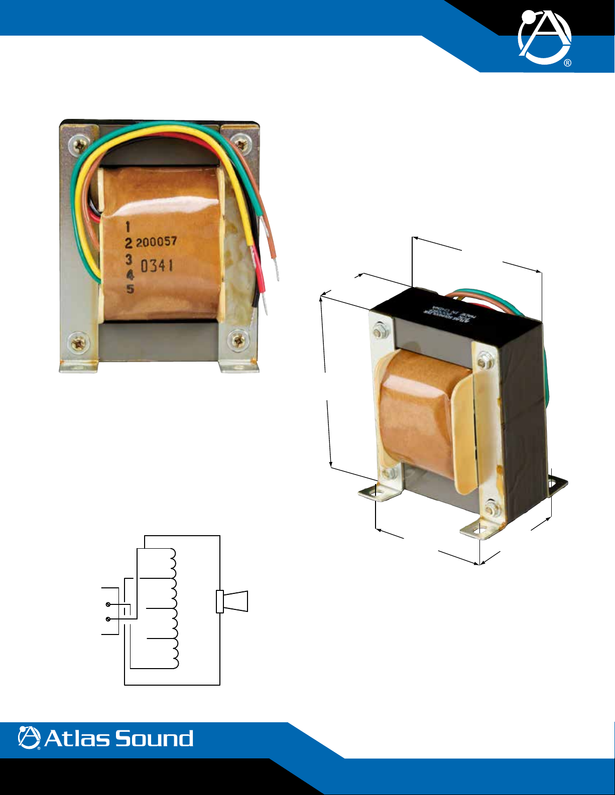
140 Watt Autoformer
Specications
Frequency Response 30Hz – 15kHz (±1dB)
Insertion Loss .3dB
Terminations 6" (152mm) Color Coded Leads
3
Core Size 1
Power Rating 140 Watts
Weight 6.25 lbs (2.8kg)
⁄8" Square (35mm)
3.4375"
(87mm)
1.375"
(35mm)
AF140
Features
• Serves as a Method for Matching Loudspeaker Loads to Amplifier
Outputs
• Suitable for Professional and Commercial Sound Applications
General Description
Model AF140 consists of a single coil autoformer with multiple taps for
maximum flexibility in match ing a wide variety of loud speak er loads to
power amplifier outputs. A single AF140 will handle loads up to 150 Watts
and by connecting two units in series, power handling capacity can be
increased to 300 Watts.
Green
5
Yellow
4
+
Com
3
2
1
Brown
Red
Black
2.75"
(70mm)
2.375"
(60mm)
Architect & Engineer Specications
Auto transformer shall be Atlas Sound Model AF140 or approved equal. It
shall be capable of handling 140 Watts of audio power with a frequency
response of 30Hz – 15kHz (±1dB).
1
Dimensions shall be 4
shall be via color-coded wire leads.
⁄8" H x 37⁄16" W x 13⁄8" D. External con nec tions
Note: The wire colors are for
©2011 Atlas Sound L.P. All rights reserved. Atlas Sound and Strategy Series are trademarks of Atlas Sound L.P. All other trademarks are the property of their respective owners. ATS0 04034 RevA 7/11
1601 JACK MCKAY BLVD. ENNIS, TEXAS 75119 U.S.A.
TELEPHONE: (800) 876-3333
FAX (800) 765-3435
identification purposes only.
AtlasSound.com
1/8
Page 2
1 Black
2 Red
3 Brown
4 Yellow
5 Green
Amplifier Rating:
50 - 80 Watts
70.7V Line
+
Common
8Ω
+
Common
1 Black
2 Red
3 Brown
4 Yellow
5 Green
Amplifier Rating:
85 - 100 Watts
8Ω
+
Common
1 Black
2 Red
3 Brown
4 Yellow
5 Green
Amplifier Rating:
115 - 150 Watts
++
Common
8Ω
Common
70.7V Line
Amplifier Rating:
(70.7V Line)
Input
(8Ω)
Output
(70.7V Line)
1 Black
2 Red
3 Brown
4 Yellow
5 Green
1 Green
2 Yellow
3 Brown
4 Red
5 Black
Amplifier Rating:
200 - 260 Watts
N.C. N.C. N.C. N.C.
“A” “B”
1 Green
2 Yellow
3 Brown
4 Red
N.C. N.C. N.C. N.C.
“A” “B”
2 Red
3 Brown
4 Yellow
5 Green
+
Common
70.7V Line
1 Black
2 Red
3 Brown
4 Yellow
5 Green
Amplifier Rating:
50 - 80 Watts
70.7V Line
+
Common
8Ω
+
Common
1 Black
2 Red
3 Brown
4 Yellow
5 Green
Amplifier Rating:
85 - 100 Watts
70.7V Line
+
Common
8Ω
+
Common
(70.7V Line)
Amplifier Rating:
1 Black
2 Red
3 Brown
4 Yellow
5 Green
Amplifier Rating:
115 - 150 Watts
++
Common
8Ω
Common
70.7V Line
70.7V Line
+
Common
(70.7V Line)
Input
(8Ω)
Output
(70.7V Line)
Amplifier Rating:
1 Green
2 Yellow
3 Brown
4 Red
5 Black
1 Black
2 Red
3 Brown
4 Yellow
5 Green
Amplifier Rating:
270 - 300 Watts
N.C. N.C. N.C. N.C.
“A” “B”
1 Black
2 Red
3 Brown
4 Yellow
5 Green
Amplifier Rating:
115 - 150 Watts
++
Common
8Ω
Common
70.7V Line
5 Green
70.7V Line
+
Common
1 Black
2 Red
3 Brown
4 Yellow
5 Green
Amplifier Rating:
85 - 100 Watts
70.7V Line
+
Common
8Ω
+
Common
1 Black
2 Red
3 Brown
4 Yellow
5 Green
Amplifier Rating:
115 - 150 Watts
8Ω
Common
1 Black
2 Red
3 Brown
4 Yellow
5 Green
Amplifier Rating:
85 - 100 Watts
70.7V Line
+
Common
8Ω
+
Common
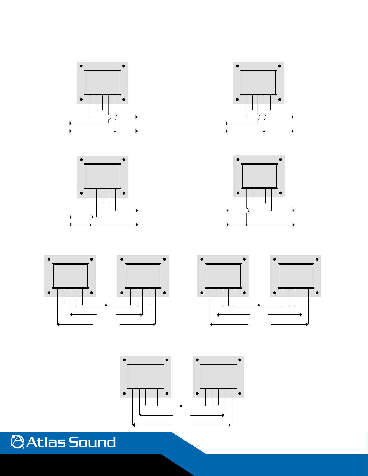
Using the AF140 Autoformer to Convert 8Ω Output to 70.7V Lines
Step 1: Determine the wattage rating of the amplifier.
Step 2: Locate the diagram below that most closely matches the rating of your amplifier and follow the connections shown.
8Ω
Common
8Ω
Common
Amplifier Rating:
30 - 45 Watts
1 Black
2 Red
3 Brown
4 Yellow
5 Green
70.7V Line
8Ω
+
+
Common
+
Common
Amplifier Rating:
85 - 100 Watts
1 Black
2 Red
3 Brown
4 Yellow
5 Green
70.7V Line
8Ω
+
Amplifier Rating:
50 - 80 Watts
1 Black
2 Red
3 Brown
4 Yellow
Amplifier Rating:
115 - 150 Watts
1 Black
2 Red
3 Brown
4 Yellow
5 Green
70.7V Line
+
Common
5 Green
70.7V Line
++
+
Common
Common
Common
©2011 Atlas Sound L.P. All rights reserved. Atlas Sound and Strategy Series are trademarks of Atlas Sound L.P. All other trademarks are the property of their respective owners. ATS0 04034 RevA 7/11
“A” “B”
1 Green
2 Yellow
3 Brown
N.C. N.C.
160 - 190 Watts
4 Red
5 Black
Input
(8Ω)
Output
1 Black
2 Red
3 Brown
4 Yellow
5 Green
N.C. N.C.
270 - 300 Watts
“A” “B”
1 Green
2 Yellow
3 Brown
N.C. N.C. N.C. N.C.
4 Red
5 Black
Input
(8Ω)
Output
1 Black
200 - 260 Watts
“A” “B”
1 Black
2 Red
3 Brown
4 Yellow
5 Green
N.C. N.C. N.C. N.C.
Input
(8Ω)
Output
2 Red
3 Brown
4 Yellow
5 Green
1 Green
2 Yellow
3 Brown
4 Red
5 Black
1601 JACK MCKAY BLVD. ENNIS, TEXAS 75119 U.S.A.
TELEPHONE: (800) 876-3333
FAX (800) 765-3435
AtlasSound.com
2/8
Page 3
Using the AF140 Autoformer
The AF140 autoformer can be used to solve a wide variety of impedance-
matching and voltage step-up/step-down problems. The key to under-
standing how to best utilize the AF140 depends upon being able to
convert both the input and output to the same unit of measure. In other
words, you must know the input voltage in order to determine the output
voltage. Likewise, the input impedance must be known to find the output
impedance. Both of these values can be determined by using simple
Ohm’s Law formulas and the reference chart.
Simply follow these steps:
Step 1: Convert the input and output to the same unit of measure using
the formulas on the circle chart.
Step 2: Calculate the ratio between the input and the desired output
(accomplished by dividing the output by the input).
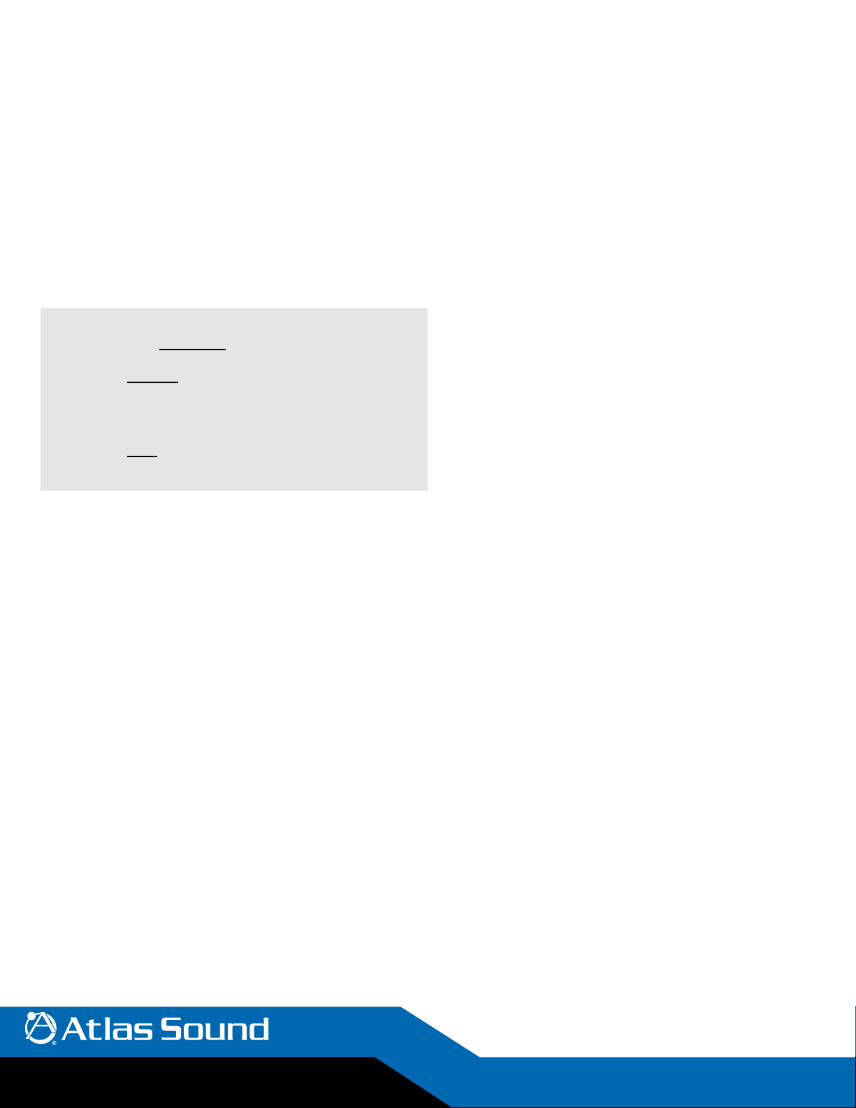
Example: Converting 100 Watt, 8Ω Amplifier Output to a 70.7V Line
OUTPUT
INPUT
• 70.7 Volts
28.3 Volts
Example: Matching Six 16Ω Loudspeakers Connected in Parallel to an
8Ω Amplifier Output
• 2.66Ω
8Ω
= 2.5 Voltage Ratio
= .332 Impedance Ratio
= RATIO
Step 3: Find the desired ratio (voltage or impedance) on the step-up or
step-down charts on pages 4 and 5 and use the input and output
connections indicated. (If the exact ratio needed is not shown on
the chart, use the closest one available.)
The exact output can be determined by multiplying the input by the ratio
shown on the chart.
Note: the “common” will be shared by both the input and output.
Also, don’t be confused by the color of the wires. They have no
meaning other than to distinguish one from another. The black
wire will not be “common” in every case.
A single AF140 will handle loads up to approximately 150 watts. For
applications requiring more power, two AF140s can be connected in
series.
The diagrams and charts on pages 6 and 7 show the connections and all
the possible step-up and step-down ratios.
One of the more common applications of the AF140 is converting 8Ω
amplifiers to “70V” lines. The handy reference guide on page 2 shows
connections for amplifiers from 30 watts to 300 watts.
©2011 Atlas Sound L.P. All rights reserved. Atlas Sound and Strategy Series are trademarks of Atlas Sound L.P. All other trademarks are the property of their respective owners. ATS0 04034 RevA 7/11
1601 JACK MCKAY BLVD. ENNIS, TEXAS 75119 U.S.A.
TELEPHONE: (800) 876-3333
FAX (800) 765-3435
AtlasSound.com
3/8
Page 4

Single AF140 Applications: 20 - 150
Amplifier
Power
20W 8.9 12.6 17. 9 31.3Ω 125.0Ω 250Ω 500Ω
25W 10.0 14.1 20.0 25.0Ω 100.0Ω 200Ω 400Ω
30W 10.9 15.5 21.9 20.8Ω 83.3Ω 166Ω 332Ω
35W 11. 8 16.7 23.6 17. 8 Ω 71.4Ω 143Ω 286Ω
40W 12.6 17. 9 25.3 15.6Ω 62.5Ω 125Ω 250Ω
45W 13.4 18.9 26.8 13.9Ω 55.5Ω 111 Ω 222Ω
50W 14.1 20.0 28.3 12.5Ω 50.0Ω 100 Ω 200Ω
55W 14.8 20.9 29.6 11. 4Ω 45.5Ω 91Ω 182Ω
60W 15.5 21.9 30.9 10.4Ω 41.6Ω 83Ω 166Ω
65W 16.1 22.8 32.2 9.6Ω 38.5Ω 77Ω 154Ω
70W 16.7 23.6 33.5 9.0Ω 35.7Ω 71Ω 143Ω
75W 1 7. 3 24.5 34.6 8.4Ω 33.3Ω 67Ω 134Ω
80W 1 7. 9 25.3 35.8 7. 8 Ω 31.3Ω 63Ω 125Ω
85W 18.4 26.0 36.8 7. 4 Ω 29.4Ω 59Ω 118 Ω
90W 18.9 26.8 37.9 7. 0 Ω 27.8Ω 56Ω 112 Ω
95W 19.5 27.5 39.0 6.5Ω 26.3Ω 53Ω 10 6 Ω
100W 20.0 28.3 40.0 6.2Ω 25.0Ω 50Ω 10 0 Ω
110 W 20.9 29.6 41.9 5.7Ω 22.7Ω 46Ω 92Ω
120W 21.9 30.9 43.8 5.2Ω 20.8Ω 42Ω 84Ω
130W 22.8 32.2 45.6 4.8Ω 19.2Ω 39Ω 78Ω
140W 23.6 33.4 47.3 4.5Ω 17. 8 Ω 36Ω 72Ω
150W 24.5 34.6 49.0 4.2Ω 16.7Ω 34Ω 67Ω
Volts Into 4ΩVolts Into 8ΩVolts Into
16Ω
Impedance
25v Line
Impedance
50v Line
Impedance
70.7v Line
Impedance
100v Line
Two AF140 Applications (Connected in Series): 160 - 300 WattsTwo AF140 Applications (Connected in Series): 160 - 300 Watts
Amplifier
Power
160W 25.3 35.8 50.6 3.9Ω 15.6Ω 31.2Ω 62.5Ω
170W 26.0 36.9 52.1 3.6Ω 14.7Ω 29.4Ω 58.8Ω
180W 26.8 38.0 53.6 3.4Ω 13.8Ω 27.8Ω 55.5Ω
190W 27.5 39.0 55.1 3.3Ω 13.1Ω 26.3Ω 52.6Ω
200W 28.3 40.0 56.5 3.1Ω 12.5Ω 25.0Ω 50.0Ω
210W 29.0 41.0 57.9 2.9Ω 11.9 Ω 23.8Ω 47.6Ω
220W 29.6 42.0 59.3 2.8Ω 11. 3 Ω 22.7Ω 45.4Ω
230W 30.3 42.9 60.6 2.7Ω 10.8Ω 21.7Ω 43.5Ω
240W 31.0 43.8 61.9 2.6Ω 10.4Ω 20.8Ω 41.6Ω
250W 31.6 44.7 63.2 2.5Ω 10.0Ω 20.0Ω 40.0Ω
260W 32.2 45.6 64.5 2.4Ω 9.6Ω 19.2Ω 38.4Ω
270W 32.8 46.5 65.7 2.3Ω 9.2Ω 18.5Ω 37.0Ω
280W 33.5 47.3 66.9 2.2Ω 8.9Ω 1 7. 8 Ω 35.7Ω
290W 34.0 48.1 68.1 2.1Ω 8.6Ω 17. 2 Ω 34.5Ω
300W 34.6 49.0 69.3 2.0Ω 8.3Ω 16.6Ω 33.3Ω
©2011 Atlas Sound L.P. All rights reserved. Atlas Sound and Strategy Series are trademarks of Atlas Sound L.P. All other trademarks are the property of their respective owners. ATS0 04034 RevA 7/11
Volts Into 4ΩVolts Into 8ΩVolts Into
16Ω
Impedance
25v Line
Impedance
50v Line
Impedance
70.7v Line
Impedance
100v Line
1601 JACK MCKAY BLVD. ENNIS, TEXAS 75119 U.S.A.
TELEPHONE: (800) 876-3333
FAX (800) 765-3435
AtlasSound.com
4/8
Page 5

Step Up Single AF140
Voltage Ratio Impedance Ratio
4 16 5, 4 5, 1 1:4
3 9 4, 3 4, 1 1:3
2.5 6.25 1, 2 1, 5 1:2.5
2.4 5.76 5, 4 5, 2 1:2.4
2.14 4.57 4, 2 4, 1 1:2.14
2 4 1, 3 1, 5 1:2
1.875 3.51 1, 2 1, 4 1:1.875
1.71 2.92 2, 4 2, 5 1:1.71
1.66 2.75 5, 2 5, 1 1:1.66
1. 4 1.96 4, 3 4, 2 1:1.4
1.33 1. 76 1, 4 1, 5 1:1.33
1.25 1.56 1, 2 1, 3 1:1.25
Step Down Single AF140
Voltage Ratio Impedance Ratio
.25 .062 5, 1 5, 4 4:1
.33 .109 4, 1 4, 3 3:1
.40 .160 1, 5 1, 2 2.5:1
.42 .176 5, 2 5, 4 2.4:1
.46 .212 4, 1 4, 2 2.14:1
.50 .250 1, 5 1, 3 2:1
.53 .281 1, 4 1, 2 1.87:1
.58 .336 2, 5 2, 4 1.7:1
.60 .360 5, 1 5, 2 1.66:1
.71 .504 4, 2 4, 3 1.4:1
.75 .562 1, 5 1, 4 1.33:1
.80 .640 1, 3 1, 2 1.25:1
Connections
Input Output
Connections
Input Output
Turns Ratio
Turns Ratio
©2011 Atlas Sound L.P. All rights reserved. Atlas Sound and Strategy Series are trademarks of Atlas Sound L.P. All other trademarks are the property of their respective owners. ATS0 04034 RevA 7/11
1601 JACK MCKAY BLVD. ENNIS, TEXAS 75119 U.S.A.
TELEPHONE: (800) 876-3333
FAX (800) 765-3435
AtlasSound.com
5/8
Page 6

Two AF140 Applications (Connected in Series): 160 - 300 Watts
A
5 Green
4 Yellow
3 Brown
2 Red
1 Black
1 Black
2 Red
3 Brown
4 Yellow
5 Green
B
*
STEP-UP: Voltage Ratio = 1.66, 2.00, 2.40, 4.00; Impedance Ratio = 2.75, 4.00, 5.76, 16.00
STEP-DOWN: Voltage Ratio = .60, .50, .42, .25; Impedance Ratio = .36, .25, .176, .062
A
1 Black
5 Green
4 Yellow
3 Brown
2 Red
1 Black
*
2 Red
B
3 Brown
4 Yellow
5 Green
1.66 2.75
2.00 4.00
2.40 5.76
4.00 16.00
Step Up
Connection
Input Output
2A, 2B
(Red)
4A, 4B
(Yellow)
4A, 4B
(Yellow)
4A, 4B
(Red)
1A, 1B
(Black)
3A, 3B
(Brown)
2A, 2B
(Red)
1A, 1B
(Black)
A
5 Green
4 Yellow
3 Brown
Turns
Ratio
1:1.66
1:2.00
1:2.40
1:4.00
2 Red
1 Black
.60 .36
1.66 .25
1.66 . 176
1.66 .062
*
B
1 Black
2 Red
3 Brown
4 Yellow
5 Green
Step Down
Connection
Input Output
1A, 1B
(Black)
1A, 1B
(Black)
2A, 2B
(Red)
1A, 1B
(Black)
2A, 2B
(Red)
3A, 3B
(Brown)
4A, 4B
(Yellow)
4A, 4B
(Yellow)
Turns
Ratio
1.66:1
2.00:1
2.40:1
4.00:1
Step Up
Voltage
Ratio
1.25 1.58
1.33 1.77
1.875 3.51
2.00 4.00
2.50 6.25
©2011 Atlas Sound L.P. All rights reserved. Atlas Sound and Strategy Series are trademarks of Atlas Sound L.P. All other trademarks are the property of their respective owners. ATS0 04034 RevA 7/11
1601 JACK MCKAY BLVD. ENNIS, TEXAS 75119 U.S.A.
TELEPHONE: (800) 876-3333
FAX (800) 765-3435
Connection
Input Output
2A, 2B
(Red)
4A, 4B
(Yellow)
2A, 2B
(Red)
3A, 3B
(Brown)
2A, 2B
(Red)
3A, 3B
(Brown)
5A, 5B
(Green)
4A, 4B
(Yellow)
5A, 5B
(Green)
5A, 5B
(Green)
Turns
Ratio
1:1.25
1:1.33
1:1.875
1:2.00
1:2.50
Voltage
Ratio
.80 .64
.75 .56
.53 .28
.50 .25
.40 .16
Step Down
Connection
Input Output
3A, 3B
(Brown)
5A, 5B
(Green)
4A, 4B
(Yellow)
5A, 5B
(Green)
5A, 5B
(Green)
2A, 2B
(Red)
4A, 4B
(Yellow)
2A, 2B
(Red)
3A, 3B
(Brown)
2A, 2B
(Red)
AtlasSound.com
Turns
Ratio
1.25:1
1.33:1
1.875:1
2.00:1
2.50:1
6/8
Page 7

Step Up (Amp Output Voltage to Match Speaker’s Voltage Requirement)
Input Taps
(From Amp)
5,4 5,1 1:4 4 16
4,3 4,1 1:3 3 9
1,2 1,5 1:2.5 2.5 6.25
5,4 5,2 1:2.4 2.4 5.76
4,2 4,1 1:2.14 2.14 4.57
1,3 1,5 1:2 2 4
1,2 1,4 1:1.875 1.875 3.51
2,4 2,5 1:1.171 1. 17 2.92
5,2 5,1 1:166 1.66 2.75
4,3 4,2 1:1.4 1.4 1.96
1,4 1,5 1:1.33 1.33 1. 76
1,2 1,3 1:1.25 1.23 1.56
Application example for “step-up” configuration:
100 Watt 8Ω amp needs to drive speakers on a 70.7V line
Step 1. Determine the output voltage of the 8Ω amplifier at 100W
Voltage equals the square root of wattage multiplied by impedance
or
SQRT(100*8) = 28.3 Volts
Output Taps
(To Speaker)
Turns Ratio Voltage Ratio Impedance Ratio
Step 2. To “step up” this 28.3 volts to the required 70.7 volts we must determine the ratio required to do so.
Ratio = OUTPUT/INPUT (output divided by the input)
70.7/28.3 = 2.5 (voltage ratio)
Using the chart below we select the settings required to provide this 2.5 voltage ratio:
From amp + to lead #2 (Red)
From amp – to lead #1 (Black)
To speaker + to lead #5 (Green)
To speaker – to lead #1 (Black
Other “Step Up” Power Rating Tap Selections for Common Amplier Outputs
Power
(Watts)
30 8 15.49 4.56 4.56 – to Lead #4 (yellow)
60 8 21.91 3.23 3.51 – to Lead #1 (black)
75 8 24.49 2.89 2.92 – to Lead #2 (red)
100 8 28.28 2.5 2.75 – to Lead #5 (green)
120 8 30.98 2.28 1.96 – to Lead #4 (yellow)
125 8 31.62 2.24 1.96 – to Lead #4 (yellow)
140 8 33.47 2.11 1.96 – to Lead #4 (yellow)
©2011 Atlas Sound L.P. All rights reserved. Atlas Sound and Strategy Series are trademarks of Atlas Sound L.P. All other trademarks are the property of their respective owners. ATS0 04034 RevA 7/11
Voltage Ratio
Closest
AF140
Ratio
Input Taps
(From Amp)
+ to Lead #2 (red)
+ to Lead #2 (red)
+ to Lead #4 (yellow)
+ to Lead #2 (red)
+ to Lead #3 (brown)
+ to Lead #3 (brown)
+ to Lead #3 (brown)
Input Taps
(To Speakers)
– to Lead #4 (yellow)
+ to Lead #1 (black)
– to Lead #1 (black)
+ to Lead #4 (yellow)
– to Lead #2 (red)
+ to Lead #5 (green)
– to Lead #5 (green)
+ to Lead #1 (black)
– to Lead #4 (yellow)
+ to Lead #2 (red)
– to Lead #4 (yellow)
+ to Lead #2 (red)
– to Lead #4 (yellow)
+ to Lead #2 (red)
1601 JACK MCKAY BLVD. ENNIS, TEXAS 75119 U.S.A.
TELEPHONE: (800) 876-3333
FAX (800) 765-3435
AtlasSound.com
7/8
Page 8

Connections
Input Output
5, 1 5, 4 4:1 .25 .062
4, 1 4, 3 3:1 .33 .109
1, 5 1, 2 2.5:1 .40 .160
5, 2 5, 4 2.4:1 .42 .176
4, 1 4, 2 2.14:1 .46 .212
1, 5 1, 3 2:1 .50 .250
1, 4 1, 2 1.87:1 .53 .281
2, 5 2, 4 1.7:1 .58 .336
5, 1 5, 2 1.66:1 .60 .360
4, 2 4, 3 1.4:1 .71 .504
1, 5 1, 4 1.33:1 .75 .562
1, 3 1, 2 1.25:1 .80 .640
Turns Ratio Voltage Ratio Impedance Ratio
Step Down (Amp output voltage to match speaker’s voltage requirement)
Application example for “step-down” configuration:
8Ω speaker needs to “receive” 100 Watts from a 70.7V line.
Step 1. We need to determine what voltage constitutes 100 Watts into this 8Ω speaker from the 70.7V line
Again, voltage equals the square root of wattage multiplied by impedance
or
SQRT(100*8) = 28.3 Volts
Step 2 To “step down” the 70.7V line to the required 28.3 volts we must determine the ratio required to do so.
Ratio = OUTPUT/INPUT (output divided by the input)
28.3/70.7 = .40 (voltage ratio)
Using the chart above we select the settings required to provide this .40 voltage ratio:
From amp + to lead #5 (Green)
From amp – to lead #1 (Black)
To speaker + to lead #2 (Red)
To speaker – to lead #1 (Black)
©2011 Atlas Sound L.P. All rights reserved. Atlas Sound and Strategy Series are trademarks of Atlas Sound L.P. All other trademarks are the property of their respective owners. ATS0 04034 RevA 7/11
1601 JACK MCKAY BLVD. ENNIS, TEXAS 75119 U.S.A.
TELEPHONE: (800) 876-3333
FAX (800) 765-3435
AtlasSound.com
8/8
 Loading...