

Page 1

Index
A
Action........................................................37
B
Band Definitions ........................................17
C
Canceling a Wakeup Call............................ 41
Check In..................................................... 37
Check Out..................................................37
Checking In A Guest .................................. 38
Checking Out a Guest.................................40
clean room code .........................................40
Clear 911 Call ............................................ 37
Clerk Information....................................... 32
D
Digit Match Table ......................................19
Band Assignment.................................... 20
Digit Dialed Table .................................. 19
Digits Dialed .......................................... 19
Surcharge ............................................... 20
Directory....................................................37
H
M
Maid Information....................................... 31
Main Menu Options ................................... 36
Main Screen............................................... 35
Main Screen Icons.................................. 36
P
PC Connections............................................ 8
Installing with KDX 500......................... 11
Installing with KSX 32/128 ...................... 9
PMS
Defining Format..................................... 26
Input Packets .......................................... 27
Output Packets ....................................... 27
PMS Interface............................................ 26
R
Reservation................................................ 37
Room Setup ............................................... 14
S
Serial Port Setup......................................... 21
Setting A Wakeup Call............................... 41
Smart Search.............................................. 44
Strip Digit Table......................................... 16
System Parameters ..................................... 25
Hotel Information....................................... 13
U
L
Logging In/Out...........................................38
47
Unpacking the InnFone ................................ 7
W
Wakeup Call ......... See Setting a Wakeup Call
Page 2

Atlas InnFone Stand Alone System
If this key is attached and the system still will not work please call technical support.
Windows Starts Up, But No Messages On The Screen
This means the WAV program was not set to start with Windows. Click on Start then
Programs then Key System US then InnFone. This should start the InnFone program, if
it doesn’t call technical support.
Problem: InnFone Starts, But Not Working Properly
Call Records are not being posted to the rooms.
This could be caused by a couple of things. Please check all of the following before calling
technical support.
1) The KSU is not sending any call record to the InnFone.
a) View SMDR log file in the InnFone to see if any recent call records have
been received. (Click on FileàViewàLogsàSMDR). (If call records are
being received then skip to InnFone receiving call records but not posting.)
b) Check dipswitch settings on SMDR. Refer to chapter 2 for correct settings.
c) SMDR led for COM port should flicker upon hanging up on a call. If this
does not flicker then double check dipswitch settings and make sure call
lasts longer then minimum call duration in KSU programming, 10 seconds
from default.
d) Double check wiring between KSU and InnFone. Make sure that the
modular cords are 6-wire type and that the DB-9 to modular connectors are
the ones supplied by Key System US. Try moving InnFone next to KSU
and use only the connectors supplied with the InnFone.
46
Page 3

5
Troubleshooting and Frequently Asked
Questions
This section contains troubleshooting information including the most common problems,
possible causes and remedies, and references to sections of the Atlas phone system and
InnFone system manuals where additional information may be found. If problems still exist
please call technical support.
Problem: PC Does Not Boot (Start), No Power
A few things could cause this. Check all of the following before calling technical support.
1) Power cord must be plugged into a 110 volt AC outlet.
2) Check outlet with voltmeter or tester to make sure there is power.
3) Check power switch on the back of the PC to make sure it is on. The side with the “-“
sign should be pushed in. (May not apply to all PCs’)
4) Check voltage selector switch on back of the PC to make sure it is set for 115v. If
this is wrong slide the switch from220v to 115v. (May not apply to all PCs’.)
5) If system beeps more then once on start up it is possible that a card may have come
loose during shipping. Please remove the cover and check all cards to make sure
they are securely fastened. Please call technical support for help with this step if you
are unfamiliar or uneasy with computers.
Problem: No Display On Monitor
This could be caused by a couple of things. Check the following before calling technical support.
1) Power cord must be plugged into a 110 volt AC outlet.
2) Check cable between monitor and PC. It should be securely fastened to the monitor
connection on the back of the PC. (Blue 15 pin connector.)
3) Check power light on monitor. If the light is not on there is no power to the monitor.
If the light is orange the monitor is not getting a video signal from the PC, check the
connection between the monitor and the PC. If the light is green the monitor is
functioning correctly check the brightness and contrast settings.
4) Make sure the monitor will support 800x600 resolution.
Problem: Windows Starts, But InnFone Does Not
System Displays Sentinel Device Not Attached
Check the Sentinel key shipped with the system to make sure it is securely fastened to the
printer port on the back of the PC. This key is shipped with the system in the box with
the manuals.
45
Page 4

¤
Note:
must be defined
The room
parameters
when creating
rooms in order
for this feature
to work
correctly.
Atlas InnFone Stand Alone System
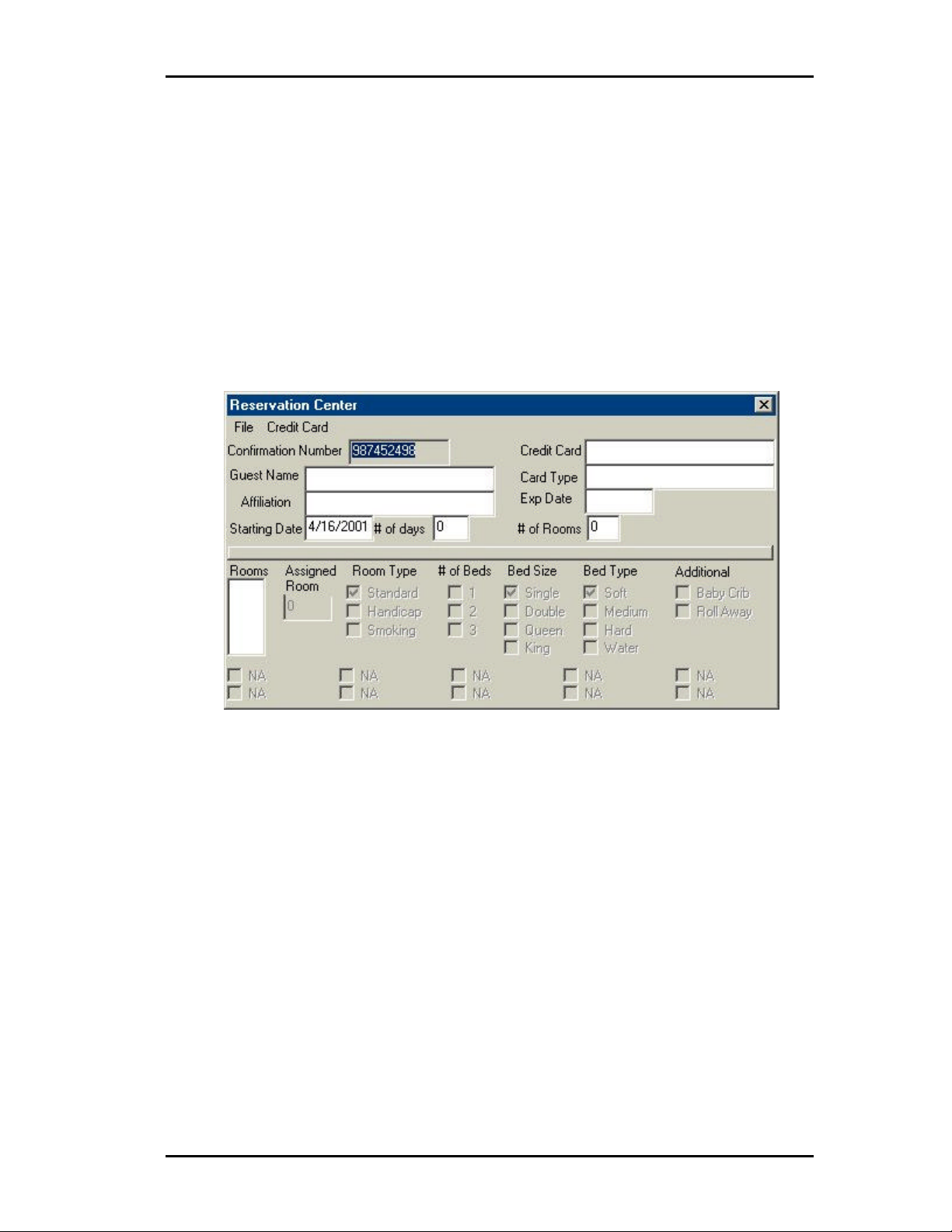
8) Expiration Date is used to enter the expiration date of the credit card.
9) The Room Number field will show the number of rooms that is
reserved for the guest. (If there are two rooms reserved the numbers 1
and 2 will show up.) To select the room to define double click on the
room #.
10) The Room Type, # of Beds, Bed Size, Bed Type and additional fields
are used to define the type of room for the reservation. Click on the
box next to each option you wish to have for the selected room number.
Adding an New Reservation
To add a new reservation click on File and then New. Any information that was on the screen
will now be blank. Using the previous descriptions fill in any fields that are relevant to the
reservation.
Removing a Reservation
To remove a reservation from the system you must first open that reservation. To open a
reservation click on File àà Select. The reservation selection screen will open. Double click
on the reservation you wish to remove from the system. The selected reservation will now
appear on the screen. To delete the reservation click on File àà Delete.
43
Page 5
Atlas InnFone Stand Alone System
¤
define different
the reservation.
R
EESSEERRVVAATTIIOONN
R
The InnFone integrates a powerful reservation system that allows the front desk to reserve
rooms for guests in advance as well as taking their personal information.
The Reservation system allows you to either view the current reservations or edit the
reservation system. When reservations are made the system will automatically assign rooms
for the reservation thus removing those rooms from the available list on that day.
Editing Reservations
Editing reservations includes adding new reservations, changing current reservations and
removing cancelled reservations from the system.
To access the Edit Reservation Screen click on Reservation and then Edit. The following
screen will appear.
S
YYSSTTEEMM
S
Figure 28 Reservation Edit Screen
1) The Guest Name field is used to enter the name of the primary guest for
the room. (This should also be the name as it appears on the credit
card.)
2) The Affiliation field is used to enter the name of the company or
organization the guest is associated with.
3) The Credit Card field is used to enter the guests credit card number
Note:
You may
parameters for
each room for
42
4) The Card Type field is used to enter the type of credit card. You may
select from pre-defined credit cards by clicking on Credit Card from
the menu and selecting the type of card to use.
5) Number of rooms is to define how many rooms to reserve for the
particular reservation.
6) Date is to define the check in date for the reservation. It should be
entered in the format of DD/MM/YY where DD=day MM=month and
YY=year. (Use 00 for the year 2000.)
7) Number of days is to define the number of days the guest whishes to
reserve the room(s) for.
Page 6
¤
Note:
If you enter the
hour
enter am or pm.
Atlas InnFone Stand Alone System
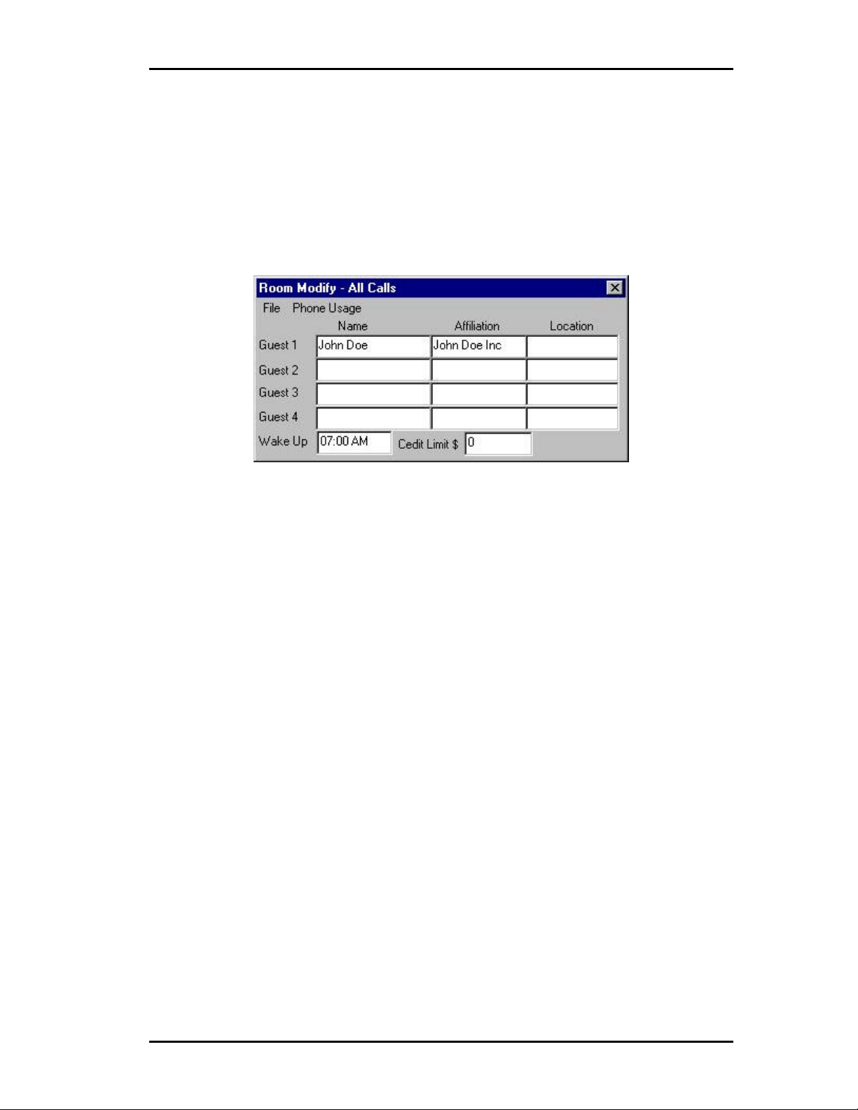
that has already been checked in you may click on Action and then Modify Room or highlight
the room by clicking on it and then right click and select modify. The Room Select screen will
open. (See Figure 4-3)
Simply double click the room you wish to modify. You may also type the room number in on
the keyboard and the InnFone will highlight the room you type. You will still need to double
click the room to select it.
Once you have selected a room the following screen will appear:
time in 24format there is
no need to
991111 E
Figure 27 Room Modify Screen
Once the Room Modify screen shows up you may enter the time in the Wake up field the
guest requested. The time is entered in a regular time format of HH:MM followed by either
AM or PM (There should be a space between the minutes and either the AM or PM). This is
a once only alarm set in the telephone system. If the wakeup call goes unanswered the system
will retry the call again in five minutes for up to three total wake attempts. You may save the
changes pressing the ENTER key or by clicking on File àà Save.
Canceling a Wakeup Call
To cancel a wakeup call follow the above procedure and simply delete the time in the wakeup
field and save the changes by pressing the ENTER key or by clicking on File àà Save.
E
MMEERRGGEENNCCYY
C
C
AALLLLS
S
The InnFone system is equipped with a 911 emergency notification. This will notify the front
desk when a room dials 911 on an outside line. The system will alert the front desk by both a
message on the screen and a voice stating there was an emergency call and the room that
dialed it.
To clear the emergency message the front desk can click on Clear 911 Call on the main
menu.
41
Page 7
Atlas InnFone Stand Alone System
b) Local – allows the guest(s) to be checked in for local calls. This will
restrict the guest from making long distance calls.
c) Internal – allows the guest(s) to make internal calls only.
d) 0+ – allows the guest(s) to make 0+ calls and local calls without giving
them access to direct dial local calls.
e) The installer may have added more options to this menu. Please
contact them as to how these options function.
Completing the Check In
To save the check in you may either press the ENTER key or click on File and then Save. If
you wish to cancel the current Check In you may either close the window by clicking on the
X in the top right hand corner or click on File and the Exit.
C
HHEECCKKIINNGG
C
There are two ways to access the check out function. You may either click on Check Out
from the main menu or highlight the room by clicking on it and then right clicking and
selecting Check Out. (If you click on Check Out from the main menu a list of all currently
occupied rooms will be displayed. (See Figure 4-3 for sample screen.) Simply double click
the room you wish to check out. You may also type the room number in on the keyboard and
the InnFone will highlight the room you type. You will still need to double click the room to
select it.)
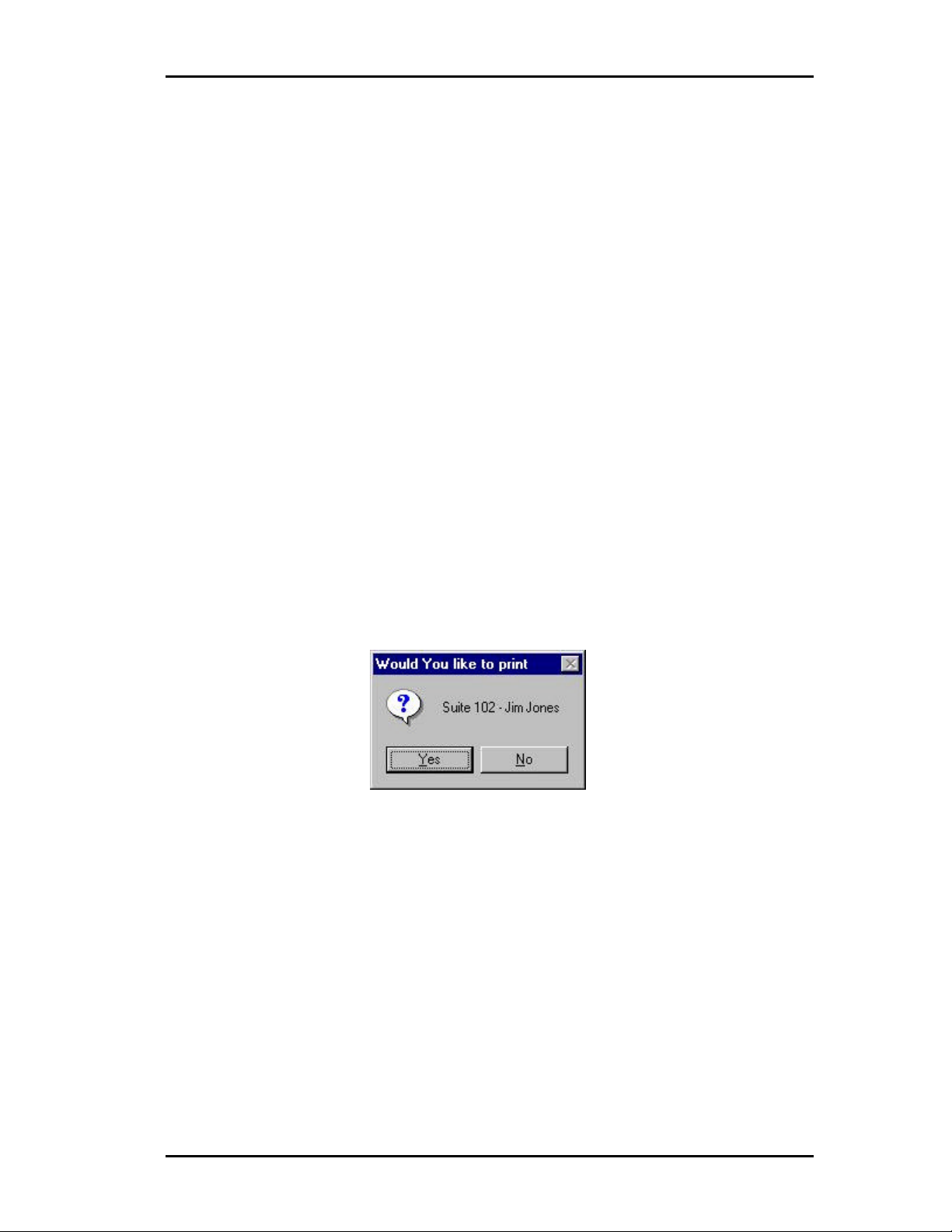
Once you have selected the guest to check out you will be prompted whether or not you wish
to print a check out report.
O
O
UUTT AA
G
G
Figure 26 Print Checkout Report Form
UUEESST
T
If you select yes the system will process the check out and print a report of any costing
associated with the room. If you select no the system will only check the room out.
Once the room has been check out the status will switch to dirty. A dirty room is not allowed
to be checked in. To clear the dirty status and switch it back to vacant the maid must dial the
clean room code (74#) from the room telephone once they have cleaned the room.
S
EETTTTIINNGG AA
S
The InnFone allows the front desk to set a wakeup call for a room. This wakeup call will be
executed by the telephone system at the time you enter. The wakeup call can either be set
upon the initial check in or at any time the room is occupied. (To set a wakeup call upon
check in, please refer to the Checking In a Guest section.) To add a wakeup call to a room
40
W
AAKKEEUUPP
W
C
C
AALLL
L
Page 8
¤
Note:
The current toll
¤
If you enter the
hour
enter am or pm.
restriction will
be displayed
across the top
of the screen.
Atlas InnFone Stand Alone System
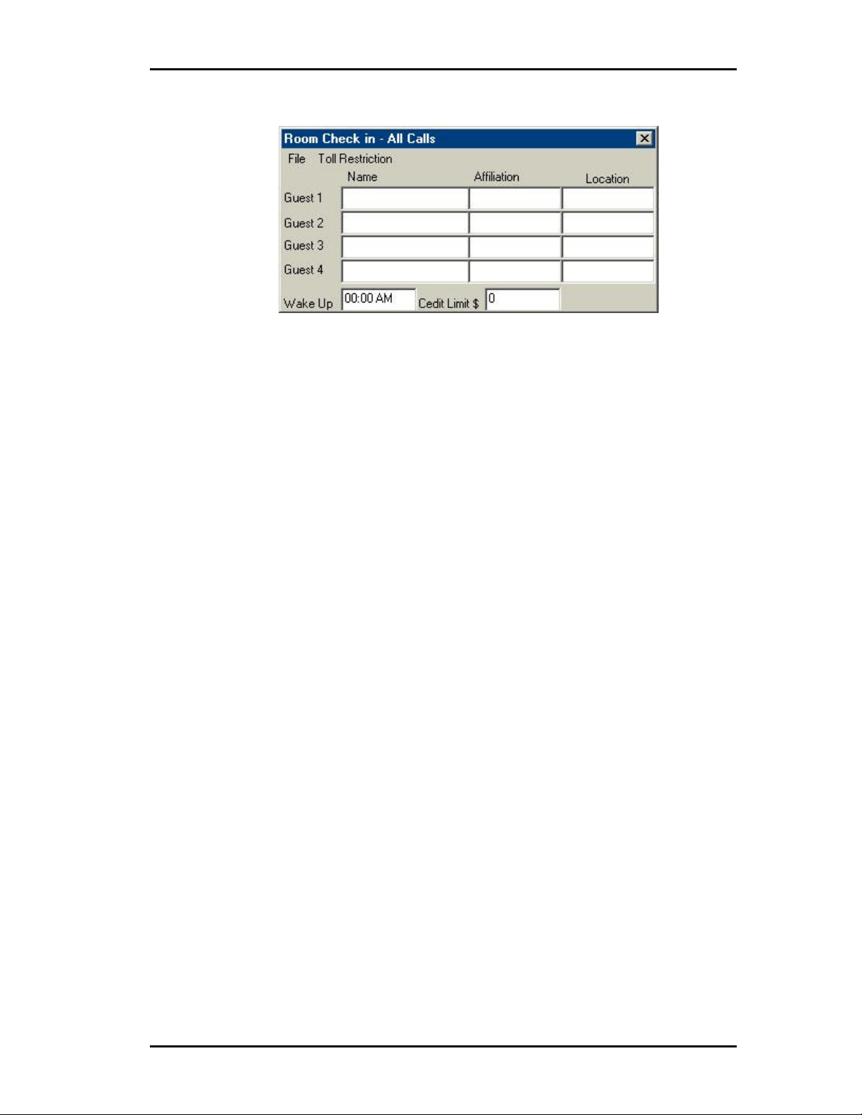
Once you have selected a room the following screen will appear:
Figure 25 Check In Screen
Name
These fields allow you to enter the name of the guest(s) staying in the room. The name
should be entered in the format of “First Name (Space) Last Name” (for example “Jim Jones”
would be a correct entry). The name entry allows the front desk to search by guests by either
first name or last name.
Note:
time in 24format there is
no need to
Affiliation
These fields are used to assign a company name to each guest. This company name can be
used to search for multiple guests within the same company when using the directory system
of the InnFone.
Location
The location field can be used to keep track of a current guest. For example if he is going to
be in a conference room or at the pool that information can be entered to track the guest down
if needed. This is also a function of some PMS systems and they will automatically update
this field.
Wake Up
This field is used to set a wake up call for the guest. The time is entered in a regular time
format of HH:MM followed by either am or pm. This is a once only alarm set in the
telephone system.
Credit Limit
This field is used to assign a credit limit to the room telephone(s). Once a guest exceeds their
credit limit the InnFone will restrict the room to intercom calls only until it is changed by the
front desk. The credit limit is entered in whole dollar amounts only.
Room Check In Menu Items
The menu on the Room Check In form also contains information regarding the check in setup.
The following is a list of options that are selectable from the menu.
File
a) Save – save the current changes and check in the room
b) Exit – closes the Check In form without checking in the guest.
Toll Restriction
a) All Calls – allows the guest(s) to make any calls without toll restriction
39
Page 9
Atlas InnFone Stand Alone System
¤
If Smart Search
L
OOGGGGIINNGG
L
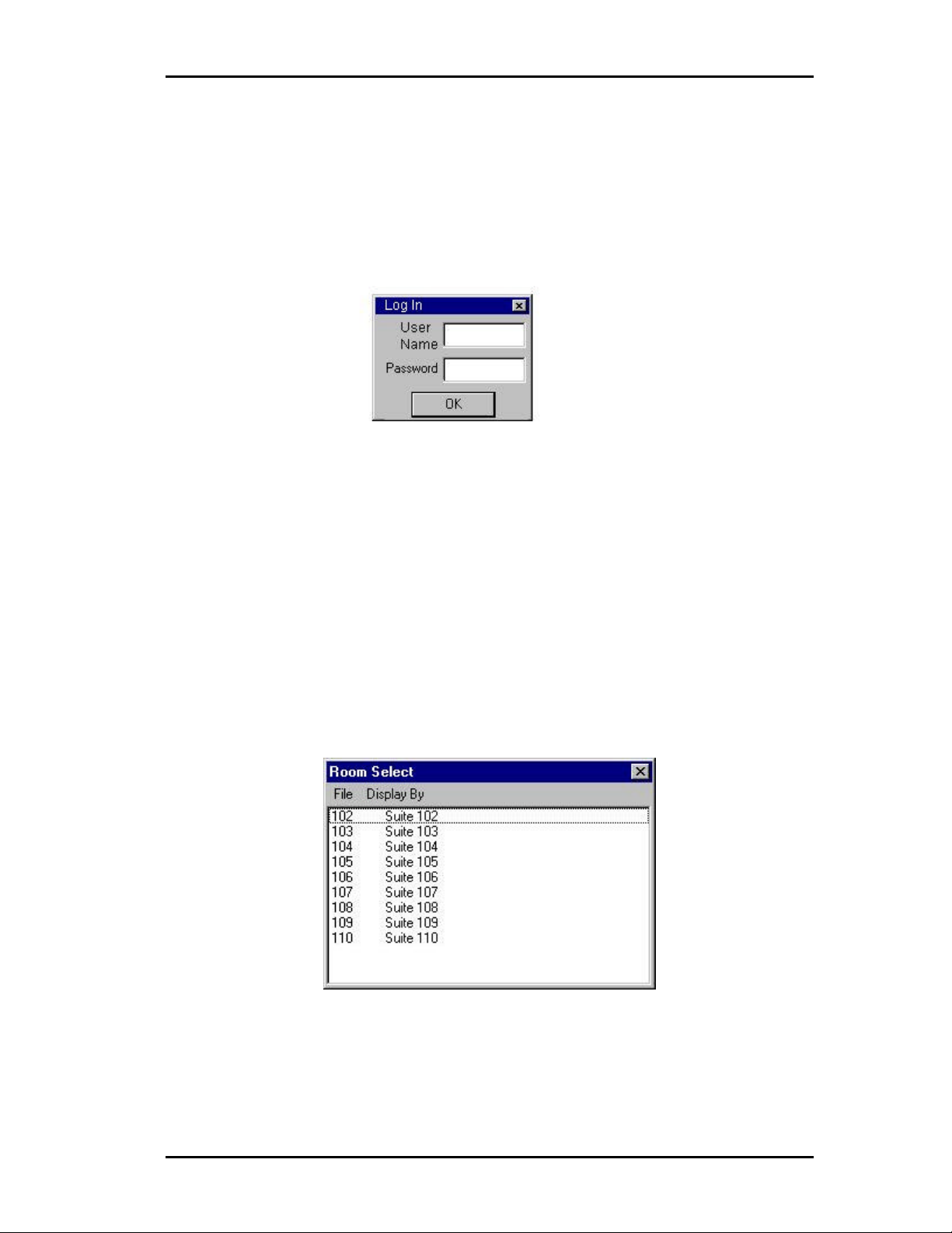
The InnFone allows for password restriction to access certain options as well as basic
functionality such as checking in/out a guest. When setup each user must log in before
proceeding any further into the system. The following is an example of the login screen:
:Screen Path:
Select:
• Actionà
• Clerk(s)à
• Log In
C
C
To access the Log In screen click on Action àà Clerks àà Log In.
To Log Out click on Action àà Clerks àà Log Out. If you forget to Log Out the system will
automatically log you out after five minutes of inactivity.
HHEECCKKIINNGG
I
N
O
T
UUT
AA G
G
UUEESST
Figure 23 Login Screen
T
N
I
//O
I
NN
I
There are two ways to access the check in function. You may either click on Check In from
the main menu or highlight the room by clicking on it then right click and select check in. If
you select to click on Check In from the Main Menu the following screen will appear if you
right click skip to the Room Check In Screen.
Note:
is enabled the
room select
screen will not
be displayed.
You will see
the Smart
Search screen
instead.
Figure 24 Room Select Screen
Simply double click the room you wish to check in. You may also type the room number in
on the keyboard and the InnFone will highlight the room you type. You will still need to
double click the room to select it.
38
Page 10

Atlas InnFone Stand Alone System
View – This menu selection allows you to view different information in the InnFone.
a) Logs – View different logs in the system. Either SMDR or PMS.
b) Rooms – View the current status of all the rooms in the system. This
screen also allows you to sort the view by status. See Room Status for
further details.
Initialize – This menu selection allows the InnFone to request all current room information
from the PMS system.
Reports – This menu selection allows you to run different reports on the system.
a) Rooms – Allows you to print a report on different type of room status.
b) Audit – Allows you to run audit reports for either day, week, month or year.
Exit – This menu selection will close the InnFone program. Doing this will stop the system
from costing any calls.
Action
The action menu contains information regarding the user operation of the InnFone.
Clerk(s) – This menu selection allows the front desk personnel to either log on or log off of
the system.
Smart Search – This menu selection opens the smart search form. This can be useful if the
smart search option is not turned on in the system.
Reserve Room – This menu selection allows the front desk to reserve a room. This is not
related to the reservation system. This would be used to reserve a room for a
particular function not for a guest.
Modify Room – This menu selection allows the front desk to modify a room that is currently
check in. You can use this to set a wakeup call, change a rooms credit limit,
change guest name information or any other options that can be set during the
check in screen.
Change – This menu option allows you to manually change the status of a room without
having to go through the check in or check out process.
Move – This menu option allows you to move a guest from one room to another.
Check In
This menu selection will initiate the check in process. It will either open the Smart Search
screen or the Room Selection screen depending on system settings.
Check Out
This menu selection will initiate the check out process.
Clear 911 Call
This menu selection will clear the emergency call message from the screen.
Reservation
This menu will give you access to the reservation system. You can choose either to edit or to
view the reservation information. Please refer to the section on reservation for more detail.
Directory
This menu selection allows you access to the directory screen. This allows you to view
current guests check in to the system.
37
Page 11
Atlas InnFone Stand Alone System
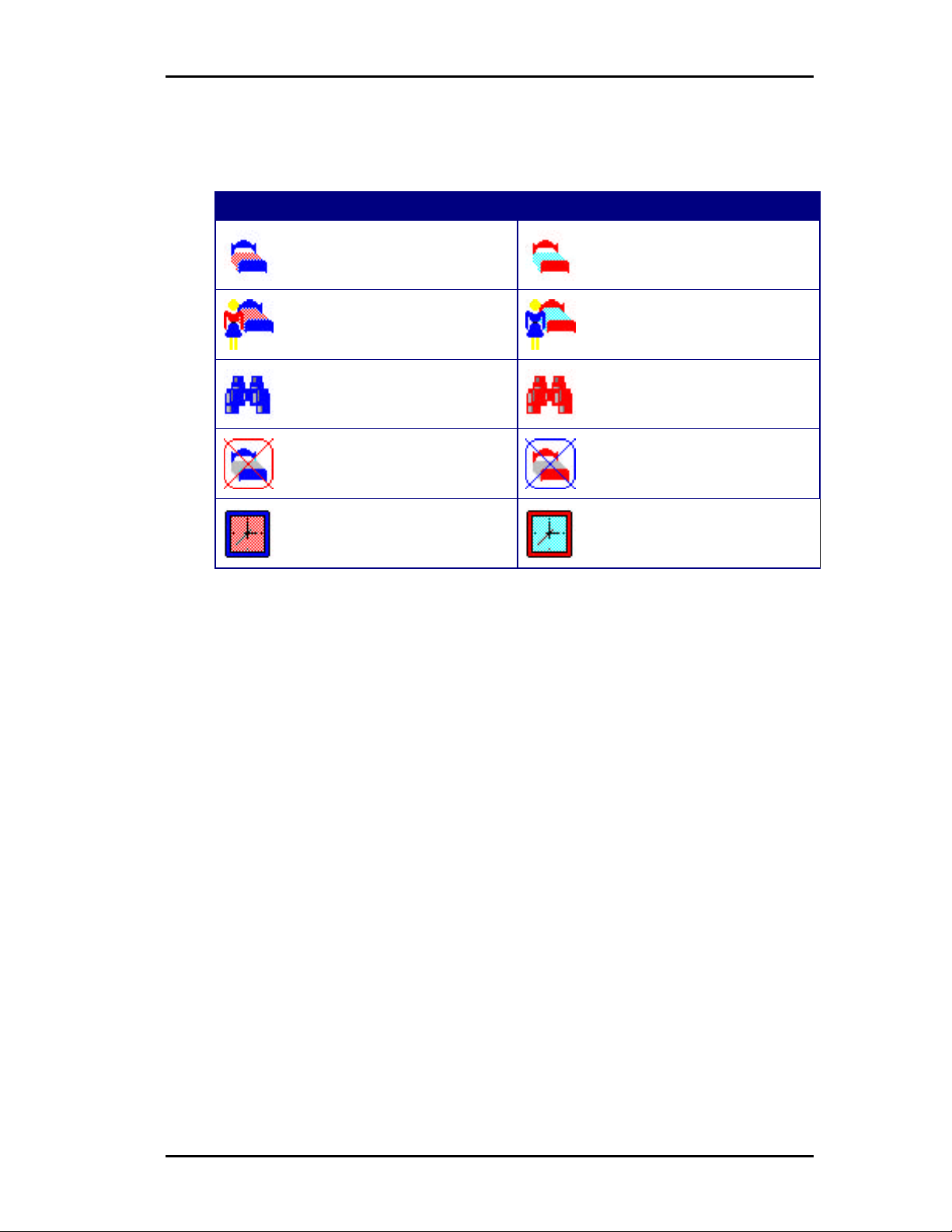
¤
while red Icons
Note:
Blue Icons
represent
Vacant status
Main Screen Icons
To use the InnFone main screen to view current information use the following guide.
Vacant Occupied
Clean Room
Clean Room
represent
Occupied
status.
To View information you may double click on any item with a “+” to the left of it. If there is
no “+” to the left that item has no more information to be displayed.
U
NNDDEERRSSTTAANNDDIINNGG
U
The main menu on the InnFone is broken up into seven selections.
Dirty Room
Needs Inspected
Out Of Service
Reserved
M
M
AAIINN
M
M
EENNUU
O
PPTTIIOONNS
O
Dirty Room
Needs Inspected
Out Of Service
Reserved
S
File
This menu contains information regarding the main operation of the InnFone.
Screen – This menu is used to manually refresh the screen to update the most recent activity.
(The screen will automatically update after 10 seconds of inactivity.)
Edit – This menu is used in setting up the InnFone. Please refer to chapter 3 for information
regarding this selection.
Icons – This menu selection is used to change the size of the icons displayed on the screen.
The options are small, large and refresh.
System – This menu selection is used by technical support to log into the system.
Reset – This menu selection is used to reset information in the InnFone. Currently the only
option is Year to Date. This option will reset all call information for the current year.
Activate – This menu selection is used to activate different features in the system. Currently
the only two options available are Smart Search and Double Click. Smart Search is
used for checking in a guest to find a particular type of room. Double click allows the
user to double click on a room to access the room menu.
Update – This menu selection is used to update information in the InnFone. This includes
36
daily room rates and reservations.
Page 12
User Operating Instructions
This section is designed to help the property owner and their employees in using the InnFone.
This will include checking In/Out a guest, setting wake up calls, modifying room statuses,
running reports and any other options that might be used in a day-to-day environment.
4
M
M
S
AAIINN
CCRREEEEN
S
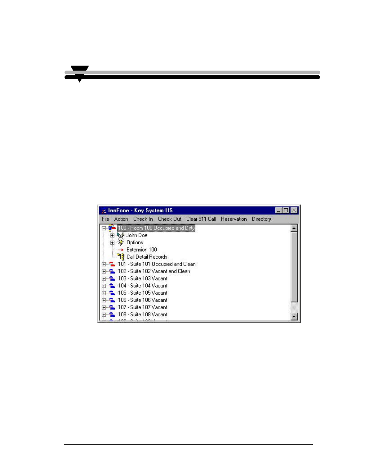
The main InnFone screen will display all current room information in a viewable tree format.
This includes room status, checked in/out, current call activity and charges, guest name(s) and
affiliations and all other settings that are assigned to the room. The following is a sample of
the main screen.
N
Figure 22 InnFone Main Screen
35
Page 13

Atlas InnFone Stand Alone System
This Page Intentionally Left Blank
.
34
Page 14
Atlas InnFone Stand Alone System
:Screen Path:
Select:
• Fileà
• Edità
• Clerks
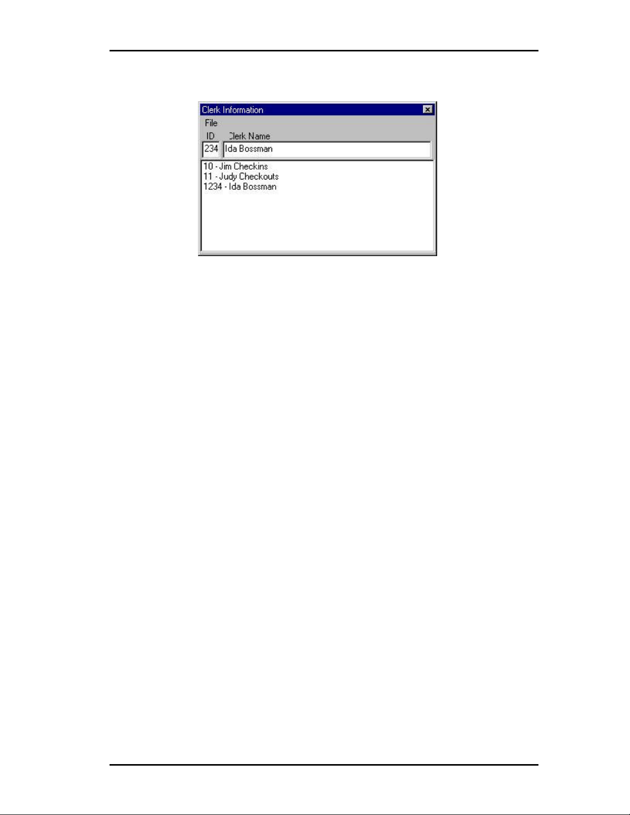
Figure 21 Clerk Information Screen
33
Page 15
Atlas InnFone Stand Alone System
¤
double click the
:Screen Path:
Select:
• Fileà
• Edità
• Maids
Note:
To select a
different maid
entry, simply
one you want
to program.
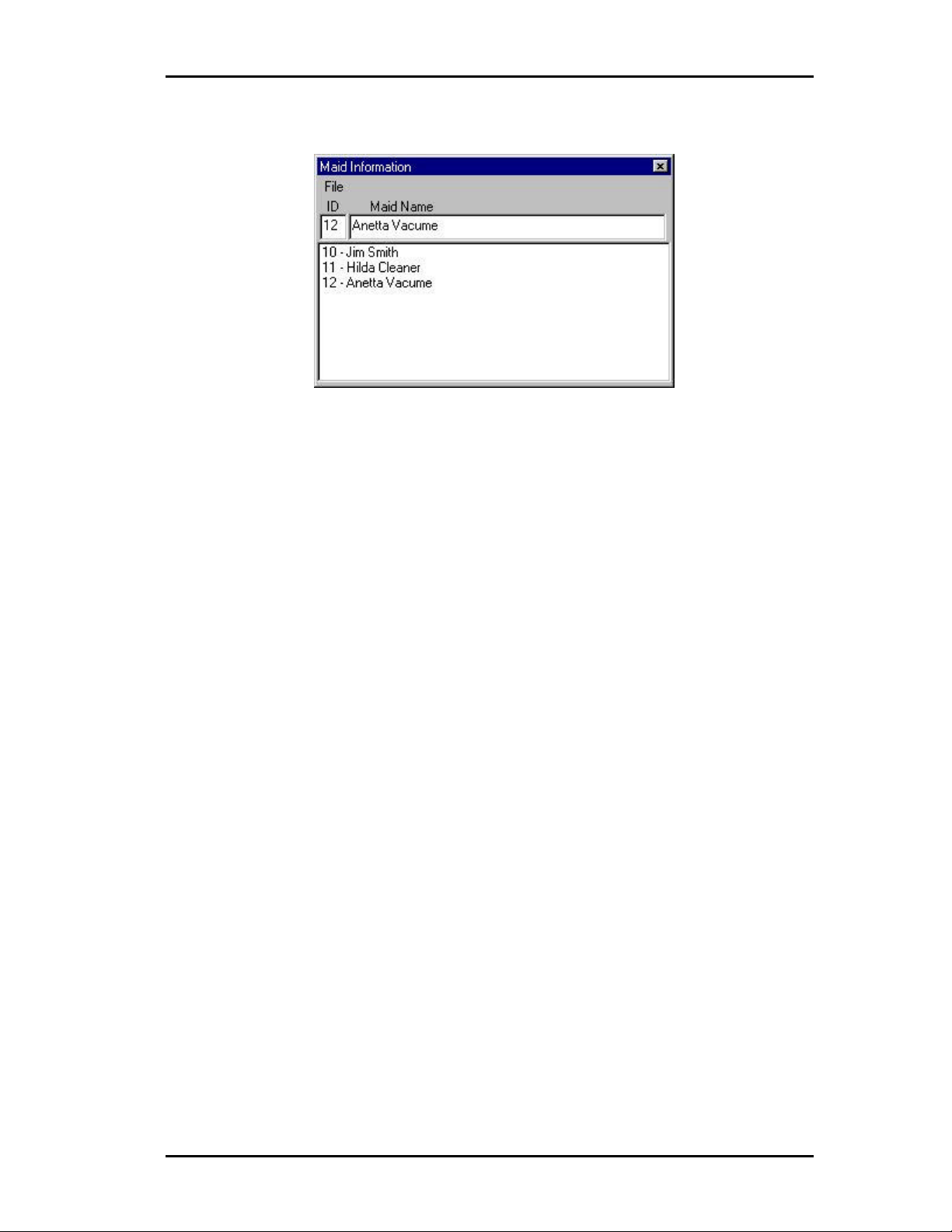
Figure 20 Maid Information Screen
ID
The ID field is used to assign the actual ID number for the maid. This field can be up to 10
digits long. However, all entries must be the same length for the feature to work correctly.
Maid Name
This field is used to assign a name to the maid. This can be in any format that is recognizable
to the front desk staff.
Maid Information Menu Items
The menu on the Maid Information form also contains information regarding the maid setup.
The following is a list of options that are selectable from the menu.
File
a) New – allows you to add a new maid ID entry.
b) Save – save the current changes. This must be done before selecting a
different maid ID entry.
c) Delete – delete the current maid ID entry.
d) Exit – closes the Maid Information form.
C
LLEERRKK
C
32
I
NNFFOORRMMAATTIIOON
I
The InnFone allows the property manager to assign unique names and passwords for each
member of their staff for tracking purposes. This information is attached to any transactions
that that person processes. This also requires the user to “Log-In” before using the system.
The following is an example of the Clerk Information screen:
N
Page 16

Atlas InnFone Stand Alone System
T
OOLLLL
T
:Screen Path:
Select:
• Fileà
• Edità
• Systemà
• Toll
Restrictionà
R
EESSTTRRIICCTTIIOONN
R
The InnFone allows for the ability to change the toll plan for a telephone when the room is
checked in. The toll plan that is assigned to the telephone can be selected from one of up to
fifteen different options. (From default there are only four options; All Calls, Local Calls O +
calls and Room to Room.) Each different toll restriction option can be assigned to select a
different toll plan from the KSU. The following is a sample of the Phone Usage Screen.
S
S
EETTUUP
P
Figure 19 Phone Usage Screen
Code
This field is the actual toll plan in the KSU that will be selected for the telephone on check in.
The toll plan used must be setup in the KSU for the feature to function correctly. Please refer
to the KSU manual for instructions.
Description
This field allows for a description of the Toll Plan. The description is what the front desk
personnel see when they are checking in a guest. They may pick any of the toll plans that are
setup.
M
M
31
I
AAIIDD
NNFFOORRMMAATTIIOON
I
The InnFone allows the property manager to assign unique maid ID numbers to their staff for
tracking purposes. These numbers can be used when cleaning rooms to alert the front desk of
current maid activity and/or location. The following is an example of the Maid Screen.
N
Page 17

Atlas InnFone Stand Alone System
CCR Format
:Screen Path:
Select:
• Fileà
• Edità
• Systemà
•
à
Figure 18 CCR Format Screen
The CCR Format screen is used to change the default call record to match with what the PMS
system is expecting. To change this format double click on the format to change and make
appropriate changes using the following variables.
Type Variable Description
Extension x Defines the extension number the call
record is for.
Trunk Number t defines the trunk the call as made on.
Starting Time a=hours
b=minutes
c=seconds
Duration e=hours
f=minutes
g=seconds
Date Of Call m=month
d=day
y=year
Telephone number n Defines the number dialed.
Cost of Call $ Defines the cost of the Call.
Sequence Number s Defines the sequence of the call (used by the
Block Check
Character
Start of Text [ Defines the start of text in the packet.
End of Text ] Defines the end of text in the packet.
Carriage Return | (shift backspace) Sends a carriage return to the PMS.
Line Feed _ Sends a line feed to the PMS.
q Sends a block check to the PMS informing
Defines the time the call started.
Defines the length of the call.
Defines the date of the call.
PMS to determine it receives all of the call
records.
it of the size of the packet.
30
Page 18

¤
Note:
All variables
are lower case
letters.
The following table is a list of all the variables that are used by the InnFone when defining
Atlas InnFone Stand Alone System
PMS Format Variables
PMS packets:
Type Variable Sample Description
Zero Fill
Left Justify
Dollar Amount
Trunk Number
Room Number
From Room
To Room
Extension
Name
Hour
Minutes
Seconds
Month
Day
Year
Credit Card #
Credit Card Name
Credit Card Exp
Date
Description
STX
ETX
o
l
$
I
r
f
t
e
n
h
m
s
x
d
y
z
v
w
c
[
]
nnnno Fills in remaining information with blank
spaces
nnnnnnnnnnnnnl Aligns the information to the left of the
packet
$$$$.$$$ Defines the format in which to send costing
information to the PMS.
iii Defines the format the trunk information is to
be sent to the PMS.
rrrr Defines the room number being sent to the
PMS.
ffff Defines the room being transferred from.
tttt Defines the room being transferred to.
eeee Defines an extension number
nnnnnnnnnn Defines a name to be sent to the PMS.
hh Sends the hour of an activity to the PMS.
mm Sends the minutes of an activity to the PMS.
ss Sends the seconds of an activity to the PMS.
xx Defines the month of an activity to be sent to
the PMS.
dd Defines the day of an activity to be sent to the
PMS.
yy Defines the year of activity to be sent to the
PMS.
zzzzzzzzzzzzzzzz Defines the credit card number on a
reservation.
vvvvvvvvvv Defines the name on a credit card for a
reservation
ww/ww Defines the expiration date of a credit card on
a reservation.
cccccccccc Defines a description of the record for the
PMS.
[STS… Defines the start of a text field for the PMS.
…rrrr1] Defines the end of a text field for the PMS.
Defining The Call Record Format
The call record format allows the InnFone to send the costed call information to the PMS
system in a format it will recognize. The default format is setup to match the Holidex
standard used by many PMS manufacturers.
The following is a sample of the CCR Setup Screen:
29
Page 19

Atlas InnFone Stand Alone System
¤
Input or Output
InnFone will do
Note:
Do not enter
when defining
packets. The
this.
Packet Type Definition
Acknowledgement Verifies that the InnFone received a recognized packet
Neg Acknowledgement Verifies that the InnFone received an unrecognized packet
Initialize Requests the PMS to resend all current room information
Enquiry Requests the PMS to send information for one particular room
Call Record Sends a call record to PMS. (Most PMS systems do not accept call
records on the same port as PMS interface.)
Call Cost Sends a call cost to the PMS
Check In Sends a check in to the PMS
Check Out Sends a checkout to the PMS
Cost Adjustment Sends an adjustment to the PMS
Transfer Moves a guest from one room to another
Room Service Sends room service charges to the PMS.
Peg Count Uses European standard for call costing and send it to the PMS.
Message waiting Changes the message waiting status for a particular room in the
PMS.
Maid Status Updates the current maid status in the PMS.
Toll Restrictions Updates the current toll restriction status of a room in the PMS.
Name Updates a guests’ name in the PMS
Department Updates a guests’ department in the PMS
Locate Updates a guests’ location in the PMS
To define a new input packet you must first know what the PMS system is expecting to
receive for the particular function you wish to define. For example if you do a checkout on
the InnFone for room 123 and the PMS requires a packet of “STS1 rrrrr1” this packet must be
defined in the InnFone.
To define this packet in the system you would do the following:
1) Click on File and then New.
2) Enter the packet format required by the PMS, (STS1 rrrrr1) using any wild
cards that are needed. (See table on next page for accepted variables for
the PMS interface.)
3) Select the type of packet from the Output menu. (Maid Statusà
VacantàDirty)
Click on File and then Save to save the new packet
28
Page 20

¤
with your PMS
of their packets
emulate a Mitel
¤
To view packet
¤
Input or Output
InnFone will do
Note:
Please consult
manufacturer
for the format
being sent to
the InnFone.
The InnFone is
setup to
system from
default.
Note:
information
sent between
the systems,
look in the
Process PMS
window.
Note:
Do not enter
when defining
packets. The
this.
Atlas InnFone Stand Alone System
Input packets
The following is a list of the available definitions for packets which are received from the
PMS and samples of predefined packets in the system.
Packet Type Definition
Are You There This is a “heartbeat” packet sent by the PMS verifying the link
between the two systems.
Acknowledgement Verifies that the PMS received a recognized packet.
Neg Acknowledgement Verifies that the PMS received an unrecognized packet.
Reset PMS system is requiring a reset of all room information.
End Defines the end of a group of information sent by the PMS.
Check In The PMS has sent a packet requesting a guest to be checked in.
Check Out The PMS has sent a packet requesting a guest to be checked out.
Enquiry The PMS is requiring information a particular room.
Cost Adjustment A cost for a particular room has been changed in the PMS.
Room Service A room service bill has been added by the PMS
Maid The current maid status is being updated by the PMS
Message Waiting The rooms’ message waiting status is being updated by the PMS.
Toll Restrictions The rooms current toll restriction is being changed by the PMS.
Name The guests name is being updated by a particular room
Locate A guest’s location is being updated by the PMS.
To define a new input packet you must first know what the PMS system is sending and why it
is sending it. For example if you do a checkout on the PMS for room 123 and it sends a
packet of “CHK0 00123” the following can be assumed:
1) On a checkout the PMS will send a packet of CHK0 followed by the room
number.
2) The room number is being expressed in a five-digit format.
To define this packet in the system you would do the following:
1) Click on File and then New.
2) Enter the packet format being sent by the PMS, (CHK0 eeeee) using any
wild cards that are needed. (See table on next page for accepted variables
for the PMS interface.)
3) Select the type of packet from the Input menu. (Check Out)
4) Click on File and then Save to save the new packet.
Output Packets
The following is a list of the available definitions for packets which are sent to the PMS and
samples of predefined packets in the system.
27
Page 21

Atlas InnFone Stand Alone System
PPMMSS I
The InnFone system allows for a bi-directional interface with many Property Management
Systems. This interface is combined into two parts
Defining the PMS Interface Format
The PMS interface format allows the InnFone to assign definitions to different type of
information received by or sent to the PMS system. By defining these packets of information
the InnFone then becomes a link between the PMS and the KSU. For example, in a system
that has been properly setup, (and supports the feature) when a front desk employee checks a
guest out from the PMS system it will send the information to the InnFone. Once the InnFone
receives the information (packet) it defines the information received and pass that information
along to the KSU and the voicemail. This allows for a single point of access for the front
desk employees. When setup correctly this function becomes seamless and eliminates the
need for having the InnFone at the front desk. This clears up space and clutter.
I
NNTTEERRFFAACCE
1) PMS – The PMS setup defines the information that is sent between the
2) Call Records – The call records setup allows the InnFone to send the
E
InnFone and the PMS system. This is usually a two-way type of
communication (bi-directional) between the systems. This means that both
systems send information that the other is setup to recognize.
costed call information to the PMS system in the format that is required.
The following is a sample of the PMS setup screen:
:Screen Path:
Select:
• Fileà
• Edità
• Systemà
• PMS
Interfaceà
Figure 17 PMS Setup Screen
There are two types of packet that may be defined. They are Input, coming from the PMS, and
Output, going to the PMS.
26
Page 22

Atlas InnFone Stand Alone System
¤
¤
system may not
the information
Note:
All variables
must be in
lower case.
Upper case
letters define a
fixed character.
Note:
Every
Telephone
supply all of
listed in their
SMDR printout
Field Type Variables
Extension – used to define the extension
number in the call record.
Trunk – used to define the trunk number in
the call record.
Start Time – used to define the starting time
of the call record.
Duration – used to define the duration of the
call.
Date – used to define the date of the call
record.
Telephone Number – used to define the
dialed digits of the call record.
Maid ID – used to define a maid id code in
the SMDR record.
x (use as many x’s as the extension length is.
If the extension length is 2 digits use xx etc.)
t (use as many t’s as the length of the trunk
number.)
aa = hours
bb = minutes
cc = seconds
ee = hours
ff = minutes
gg = seconds
mm = month
dd = day
yy = year
n (use as many n’s as the maximum number
of digits that the SMDR will print out. The
Atlas systems send out 20 digits.)
o (the letter o)(use as many o’s as you need to
define the maid id code.)
Ring Duration – used to define the incoming
ring duration on a call record.
After defining the variables in the call record the type of the record must be defined. There
are seven different types of definitions for call records. They are:
1) Station to Station – defines call as a station-to-station call.
2) Station to Trunk – defines call as an outgoing trunk call
3) Trunk to Station – defines call as an incoming trunk call
4) Station Alarm – defines call as an alarm for a particular station
5) Trunk Alarm – defines call as an alarm for a particular trunk
6) Emergency Alarm – defines call as an emergency call (911)
7) Wake Up – defines call as a wake up call.
To define the call records simply click on Type Of from the menu and select the appropriate
call type for the current record.
S
YYSSTTEEMM
S
P
AARRAAMMEETTEERRS
P
The System parameters fields are only to be changed by Key System US technical support.
S
hh = hours
ii = minutes
jj = seconds
25
Page 23

Atlas InnFone Stand Alone System
Undefined
Same call
Defining Call Records
When an undefined call record shows up in the SMDR Format form it will be displayed
exactly as received by the InnFone. To define this as a valid type of call record the
information in that call record must be replaced with predefined variables. The following are
examples of an undefined call record and then the defined call record.
record with
defined
parameters
Figure 15 Undefined SMDR Format
Figure 16 Defined SMDR Format
The following table is a list of all variables that can be used when defining the SMDR format.
24
Page 24

¤
Note:
XON/XOFF
must be
enabled under
the menu
option
Enableà
XON/XOFF
Atlas InnFone Stand Alone System
Data Bits
This field is used to define the data bits required by the connecting device. Your options are
four through five. To select a different data bit simply click on the new selection.
XON/XOFF
This field is used to define the characters used when the connecting device requires an
XON/XOFF condition. To enter a new value, simply delete the current value and type in
what is required by the connecting device.
Communication Port Menu Items
The menu on the communications port form also contains information regarding the
communication port setup. The following is a list of options that are selectable from the
menu.
File
a) Exit – closes the communication port form
b) Save – saves the current changes in the communication port form.
Enable
a) XON/XOFF – enables the XON/XOFF field in the communication port
form.
b) Is Modem – defines the current communication port as a modem.
SSMMDDRR F
:Screen Path:
Select:
• Fileà
• Edità
• Systemà
• SMDR
Formatà
F
OORRMMAAT
The InnFone system allows for the SMDR information to be formatted to match the records
being sent out by the telephone system. If the system receives any calls that do not match an
already defined format there will be an audio notice and the record will be displayed under the
SMDR Format form. The following is an example of an SMDR Format form.
T
Figure 14 SMDR Format form
The form is divided into two parts. The first section is the current record to be defined. The
23
lower section is all of the currently defined and undefined records in the system.
Page 25

Atlas InnFone Stand Alone System
:Screen Path:
Select:
• Fileà
• Edità
• Systemà
• COMM
Portsà
• Select COMM
port to setup
that the telephone system will understand and sends the translated
information out the SMDI port.
CCR Used to send processed call records to PMS system.
The following screen is an example of the SMDI communication port setup. (All other
communication ports have a similar screen, with the only difference being the header on the
top of the window.)
Figure 13 SMDI Communications Port
Communication Ports
This field is used to select the physical communications port that is used in the computer for
sending and receiving data. To change you may simply click on the port number you wish to
change it to.
Handshaking
This field is used when the system being attached to the InnFone requires a handshaking
method. The three options are:
CTS Clear to Send. The system holds the clear to send signal high.
DSR Data Set Ready. The system will hold the DSR signal high.
DTR Data Terminal Ready. The system will hold the DTR signal high.
Stop Bits
This field is used to define the stop bits required by the connecting device. To change the
values simply click on the value required by the connecting device.
Baud Rate
This field is used to select the baud rate at which information will be sent and received. To
select a different baud rate simply click on the speed that is required by the connecting device.
Parity Type
This field is used to define the parity required by the connecting device. There are five
choices; none, even, odd, mark or space. To select a different parity type simply click on the
new selection.
22
Write Delay
This field allows for a delay to be added before any packet is sent out. The write delay is in
milliseconds. To enter a new write delay simply delete the current value and replace it with
the value required by the connecting device.
Page 26

Atlas InnFone Stand Alone System
¤
instructed to do
Max Digits
This is the maximum number of digits from the number dialed that will be displayed. This
field does not include any digits that are removed in the strip digit table. For example on local
calls you only need to display seven digits in most circumstances. If this field is left blank all
dialed digits will be displayed.
Setup Time
This is the amount of time you wish to remove from the total duration of the call to allow for
dialing. Since most phone systems start call timers as soon as the first digit is dialed on a line.
For example if your setup time is ten seconds and a call lasts for one minute the call will only
be billed as fifty seconds.
Grace Period
This could be referred to as the minimum time for a call to be valid for billing. This field is
applied after the setup time has been removed from the total duration of the call. For example
if a call lasts for one minute and the setup time is ten seconds the call has a billable length of
fifty seconds. If your grace period is more then fifty seconds the call will not be billed. If
your grace period is less then fifty seconds the call will be billed.
Digit Match Menu Items
The menu on the band definition form also contains information regarding the band definition
setup. The following is a list of options that are selectable from the menu.
File
a) New – allows you to add a digit match entry.
b) Save – save the current changes. This must be done before selecting a
different digit match entry.
c) Delete – delete the current digit match entry.
d) Exit – closes the digit match form
Select
a) Match – allows you to select another digit match.
Type
a) Incoming – allows you to define an incoming call for records
b) Outgoing – allows you to define an outgoing call for records
S
EERRIIAALL
S
Note:
The SMDI and
SMDR port
parameters
should only be
changed if
so by technical
support.
21
P
P
The InnFone allows for the installer to setup the parameters for the serial ports to match what
is required by either the telephone system or the PMS system that the InnFone is to work
with. Each different port in use can be defined with its own unique parameters. The four
types of ports include:
SMDI Used for sending information to the telephone system.
OORRTT
S
S
SMDR Used for receiving call records and other type of SMDR printouts from the
PMS Used for receiving and sending information to/from the PMS system. The
P
EETTUUP
system.
InnFone then interprets this information and translates it into information
Page 27
Atlas InnFone Stand Alone System
¤
for calls simply
assign the digit
match to a band
match table, best match entries are automatically routed into place preceding the subordinate
match.
Wildcards are also programmable in the digit match table. They are used to program a group
of numbers in a single string. Wildcards are very powerful and can be extremely useful in
minimizing the number of keystrokes when programming. However they can also cause
unanticipated and undesirable results when they are not used properly. The wild card digit
used in the InnFone is the character “X”.
The digit match table illustrated on the previous page has been constructed to provide an
understanding of how the digit match table operates and how digit match strings and
wildcards interact. The information contained in the digit match table is partially fictitious
and to be used for the purpose of illustration only. Some entries have been exaggerated to
stress the importance of considering all possibilities before using wildcards. Keep in mind
while studying the examples described in this section, the priorities of the digit match entries
are as follows; first priority is “specific digit”, second priority is “X”
Examples
Digit Match Entry Description of Consequence
0 VS
01 VS
011
1 VS
1XXX5551212
1 VS
1800 VS
1877 VS
1888
If the number dialed is 0(561) 555-1212 it will match all
three entries when the first digit is processed through the
table once the second digit is processed only the entry of “0”
will match and the call will be processed according to that
match.
If the number dialed was 011-9876543 the best match for the
call would be “011” rather then “0”
If the number dialed is 1(561) 555-1212 both the entries of 1
and 1XXX5551212 would match the first digit, however, the
best match for the call would be the 1XXX5551212.
If the number dialed is 1(800) 123-4567 the system will
match to all three entries on the initial digit. Once the second
digit is compared only 1800,1877 and 1888 will match.
Following this pattern only 1800 would match the called
number.
Description
This field allows for a description of the digits dialed for later reference.
If you wish to
set a flat rate
with no call
costing and
apply a
surcharge.
Note:
20
Band Assignment
This field allows you to select the band assignment to be associated with the digit match
entry. To select the band to assign to the specific entry double click on that band. The
InnFone will then highlight that selection.
Surcharge
By entering a value in this field the InnFone will apply a surcharge to the call. For example if
a digit match has a surcharge of $.25, $.25 will be added to the total cost of the call. This
field does not very by time it is a fixed amount.
Page 28

¤
click the one to
¤
is not very long
there will be no
Digit Match Table
The digit match table is the key to the InnFone’s flexibility when it comes to call costing.
This table consists of up to 9999 entries that can be compared to the number dialed to find a
match for costing the call. The table also supports a wild card entry of “X” to represent any
digit. The following is an example of a digit match form:
:Screen Path:
Select:
• Fileà
• Edità
• Call Costingà
• Digit Match
Atlas InnFone Stand Alone System
Select
a) Band – allows you to select another band definition.
Type of Call
a) Long Distance – tells the PMS system this is a long distance call
b) Foreign – tells the PMS system this is a foreign call
c) Local – tells the PMS system this is a local call.
Note:
To select a
different digit
match entry,
simply double
program.
Note:
If the entry list
scroll bars on
the right hand
side of the list.
Figure 12 Digit Match Table
Digit Dialed Table
This list shows all of the currently defined digit match entries in the system. You can scroll
through the list by using the up and down arrow on the right hand side of the list. To select an
entry simply double click the entry to modify. The InnFone automatically sorts this list in
order.
Digits Dialed
This field represents the actual digits to be matched to the call record. The digit match table is
used to determine the rate of a call or the cost of a call. Each entry contains a series of digits
identifying various call types. These digits are compared to the digits dialed by the user.
Once a match is encountered in the digit match table, the software refers to the band definition
associated with the digit match entry to determine the rate of the call. Each entry can use a
different band definition with different rate information to accommodate various applications.
19
The digits are stored in the digit match table, best match first, for example “976” is the best
match for a “976” call opposed to just the digit “9”. When editing or adding to the digit
Page 29

Atlas InnFone Stand Alone System
¤
double click the
¤
field the system
:Screen Path:
Select:
• Fileà
• Edità
• Call Costingà
• Band
Note:
To select a
different band
entry, simply
one you want
to program.
Band
This is the actual band number being used. This number can be between 1 and 9999. The
InnFone will automatically sort the band numbers in order once a new band is saved. If a
duplicate band is entered the system will not allow it to be saved.
Description
This field allows for a description of the band being programmed. This allows for easy
recognition of the band when setting up the digit match table.
Figure 11 Band Definitions
Note:
If there is no
entry in the
second “Next”
will default to
60 seconds.
Number of Sec
This field allows for different rates for different time periods of the call. The “First” field will
be the first part of the call in seconds. In the example above there is an entry of 60 indicating
one minute. This entry can be up to 9999 seconds. The next fields will be added onto the
first field. If there is no entry in the next “Next” field the system will continue to use the
current “Next” field. These fields can also be up to 9999 seconds.
Rate per Minute
The actual charge per minute is defined here. This charge is determined by minute. For
example if you had a duration of 30 seconds and a charge of $1.00 in the “First” field the first
30 seconds would only be charged $.50 and then the system would look at the first “Next”
field.
Tax Tables
The tax tables are used to add tax onto the total cost of a call. Each tax entry is entered in a
percent format. Each tax is calculated on the total cost of the call before tax and then added
onto that total. The City, County, State, Federal and additional are displayed merely as a
guide to what taxes the property owner may want set up.
Band Definition Menu Items
The menu on the band definition form also contains information regarding the band definition
setup. The following is a list of options that are selectable from the menu.
File
a) New – allows you to add a band definition entry.
b) Save – save the current changes. This must be done before selecting a
different band definition entry.
c) Delete – delete the current band definition entry.
18
d) Exit – closes the band definition form
Page 30

¤
:Screen Path:
Select:
• Fileà
• Edità
• Call Costingà
• Strip Digits
Note:
To select a
different strip
digit entry,
simply double
click the one
you want to
program.
Digits
The digits field defines the actual digits to be removed from the number dialed. You can use
“X” as a wild card to represent any number. Use the letter “X” in place of any digit that is to
be removed. The above example would remove the first seven digits from any number
starting with “1010”.
Atlas InnFone Stand Alone System
Figure 10 Strip Digit Table
Description of
This field allows you to assign a description of the strip digit information for future reference.
Strip Digit Menu Items
The menu on the strip digit form also contains information regarding the strip digit setup. The
following is a list of options that are selectable from the menu.
File
a) New – allows you to add a strip digit entry.
b) Save – save the current changes. This must be done before selecting a
different strip digit entry.
c) Delete – delete the current strip digit entry.
d) Exit – closes the strip digit form.
Band Definitions
The band definition form is used to define the actual rate to be applied to the call. The
programmable band table can contain up to 9,999 entries, allowing for extreme flexibility for
call costing. Several options are available to determine the actual cost of the call. Each of
these options can be programmed to suit various applications. The following is a sample of a
band definition form:
17
Page 31

Atlas InnFone Stand Alone System
Under the other selection there will be additional options that may be defined for the current
room. These options are defined under the Room Other setup screen.
Other
R
OOOOMM
R
O
O
The InnFone allows the property to define additional information for room descriptions, Ie.
Kitchenette, ocean view, pool view etc…
The following is an example of the Room Other screen.
:Screen Path:
Select:
• Fileà
• Edità
• Systemà
• Room Other
R
TTHHEER
Figure 9 Room Other Screen
To add additional options to the room setup simply enter a description into on of the blank
fields on the Other screen and then save the changes. These options will now be available
when defining rooms in the setup and when using the reservation system or smart search.
C
C
AALLLL
C
OOSSTTIINNGG
C
There are three parts associated with setting up the call costing. These are the strip digit table,
band definition and digit match table. In order for the call accounting to function correctly all
three items should be setup.
S
S
EETTUUP
P
Strip Digit Table
The strip digit table is used to remove dialed digits off of the beginning of the dialed number
field. For example if a guest dialed “1010xxx” followed by a telephone number the InnFone
system could be set up to remove the “1010xxx” from the number and the cost the call as a
normal outgoing call. The following is sample of a Strip Digit Table:
16
Page 32

Atlas InnFone Stand Alone System
11) The nightly rate is used to charge the room rate as part of the bill.
Room Menu Items
The menu on the room form also contains information regarding the room setup. The
following is a list of options that are selectable from the menu.
File
a) New – allows you to add a new room
b) Save – save the current changes. This must be done before selecting a
different room.
c) Delete – delete the current room.
d) Exit – closes the room form.
e) Duplicate – make duplicate copies of the current room with different
room numbers
Room
Under the Room selection you will see the following options:
a) Select – used to select a different room.
b) Reserved – used to reserve a room.
c) Type – used to select the room type, either Standard, Handicap or
Admin.
d) Bed Size – used to select the size of bed in the room. This feature is
used as part of the reservation system.
e) Bed Type – used to select the type of bed in a room. This feature is
used a part of the reservation system.
f) Additional – used to define additional items that may be available in
the room such as a crib, rollaway bed or a sofa bed.
Toll Restriction
Under the Toll Restriction selection you will see the following options. These options are set
when a guest is checked in. (These are the default options there may be more added under the
Toll restriction setup.)
a) All Calls – the room is not restricted to from making any type of call.
b) Local – the room is restricted to making local calls only.
c) Internal – the room is restricted to making intercom calls only.
d) O+ − the room is restricted to making O+ and local calls only.
Billing
Under the billing selection you will see the following options. These are used to determine if
the current room is billed for the different selections when a call is made.
a) Surcharge – determines whether the surcharge from the call will be
billed to this room.
b) First Minute – determines whether the first minute charge from the call
will be billed to this room.
c) Additional Minutes – determines whether the additional minute charge
from the call will be billed to this room.
15
Page 33

Atlas InnFone Stand Alone System
¤
¤
R
OOOOMM
R
:Screen Path:
Select:
• Fileà
• Edità
• Rooms
Note:
To select a
different room,
simply double
click the room
you want to
program.
S
S
The Room Setup form is used to set up the room information for the property. This includes
such fields as extension numbers, number of beds, type of room, phone usage and billing
options along with other possible selections. The room setup in this form will be what is
displayed on the main screen of the InnFone. The following is a sample of the Room form.
EETTUUP
P
If you have
multiple
extensions per
room there is
no need to
create a
different room
for each
extension.
Note:
Figure 8 Room Form
1) The room number field is the actual room number to be displayed on the main
InnFone screen.
2) The number of beds field is used for the reservation system to define how many beds
are in the room.
3) The credit limit field is used to enforce a credit limit on a room. This field is
automatically updated when a room is checked in.
4) The description field is used to give a description to the room.
5) The extension field is used to define the extension(s) in a room. If you wish to enter
multiple extension separate them with a “ ” (space). For example if a room had an
extension of 100 and a data port extension of 120 you would enter “100 120”. Any
extensions entered in this will be included in the billing for this room.
6) The guest field is used to display the guests name who is currently occupying the
room. This field is automatically updated when a room is checked in.
7) The Affiliation field is used to assign an affiliation to a guest. This is also referred to
as company on some systems. This field is updated on check in and is not required.
8) The wake up field displays the time for any current wake up call for the room. This
field is automatically updated when a room is checked in.
9) The total charge field is used to display the total current charges for the room. This
field cannot be edited.
10) The check in field is used to display the date that the current guest was checked in.
This field is automatically updated when a room is checked in.
14
Page 34

Administration
This section will assist the installer with setting up the system for use. Included in this will be
setting up the rate and digit match tables, setting up rooms, setting up strip digit tables, hotel
information, serial ports and system parameters.
3
H
OOTTEELL
H
The Hotel Information form contains information about the property the system is installed at.
This information will be displayed as a header for any report the system prints out. The
following is the screen you will see while editing the Hotel Information.
:Screen Path:
Select:
• Fileà
• Edità
• Hotel
Information
I
NNFFOORRMMAATTIIOON
I
N
Figure 7 Hotel Information
1) The Name field is for the name of the property
2) The Address fields are for the address of the property or any other information you
may want displayed as a header for the reports.
3) The Zip Code field is for the zip code of the property.
4) The Phone Number field is for the telephone number of the property.
5) The Room Rate Tax(s) field allows the property owner to apply up to five different
tax rates on a room when they are utilizing the room rate feature. (This is enabled
while setting up the room. See next page.)
13
After entering the information click on File and then Save to save your changes.
Page 35

Atlas InnFone Stand Alone System
Wiring Diagram
Figure 5 KDX-MDF Diagram
12
Figure 6 SMDRU to InnFone
Page 36

Atlas InnFone Stand Alone System
¤
I
NNSSTTAALLLLIINNGG WWIITTHH
I
Note:
When using a
long cable run
with two RJ
type jacks at
either end, one
side should be
reversed when
using standard
reversed
modular cords
at both ends.
(Such as the
ones Key
System US
supplies.)
Figure 4 InnFone PC to SMDR-E Connections
KKDDXX--550000
Installing the InnFone on a KDX-500 system requires no special software in the KSU, as the
standard software will support the InnFone functionality. The only hardware required would
be an SMDRU card. (Please refer to the KDX-500 installation manual on information for
installing the SMDRU card.)
To enable the COM ports on the SMDRU card for normal operation you should have DIP
switches 5,6 and 7 in the on position. (If they are off the COM ports will function in test
mode only.)
Attaching InnFone to SMDRU
The InnFone attaches to the SMDRU using two serial connections. These cables are supplied
with the InnFone and are labeled with their respective connections.
The cable kit that is provided with the Innfone will include two 6 conductor mudular cords
two DB-9 to modular adapters and two serial to USB adapters. To connect the InnFone to the
SMDRU connect one of the modular cords (supplied) to the RJ jack labeled J2 on the KDXMDF (right hand side of the main cabinet) and connect the other end of the modular cord to
the DB-9 to USB connector labeled Com 2. Plug this connector into one of the USB
connectors on back of the InnFone PC. Plug the remaining modular cord (supplied) into the
RJ jack labeled J4 on the KDX-MDF and connect the other end to the DB-9 to USB connector
labeled Com 1. Plug this connector into the remaining USB connector on back of the InnFone
PC.
11
Page 37

Atlas InnFone Stand Alone System
Figure 2 SMDR-E Diagram
Wiring Diagram
Figure 3 Serial to USB Adapter
10
Page 38

Atlas InnFone Stand Alone System
¤
¤
ersion
inside the KSU
I
NNSSTTAALLLLIINNGG WWIITTHH
I
Note:
When using a
long cable run
with two RJ
type jacks at
either end, one
side should be
reversed when
using standard
reversed
modular cords
at both ends.
(Such as the
ones Key
System US
supplies.)
KKSSXX--3322//112288
When installing the InnFone on either a KSX-32 or KSX-128 there are a couple of items that
need to be checked before proceeding.
1) The system must already have an SMDR-E unit installed (please refer to
KSU manual on directions on installing the SMDR-E)
2) The SMDR-E dipswitches should be set for the InnFone. (Switches 1, 3, 4
and 5 should be on. All others should be off.)
3) The system must have InnFone version software installed. (This can be
determined by pressing the “PROG” key on an idle display phone. The
word “InnFone should be displayed on the screen before the software
version) If the InnFone and KSU were purchased together the KSU should
have InnFone software installed.
Attaching InnFone to SMDR-E
The InnFone attaches to the SMDR-E using two serial connections. These cables are supplied
with the InnFone and are labeled with their respective connections.
The cable kit that is provided with the Innfone will include two 6 conductor mudular cords,
two DB-9 to modular adapters and two serial to USB adapters. To connect the InnFone to the
SMDR-E connect one of the modular cords (supplied) to the RJ jack labeled Com 2 on the
SMDR-E and connect the other end of the mudular cord to the DB-9 to USB connector
labeled Com 1 (supplied). Plug this connector into the back of the InnFone PC to one of the
USB connectors. Plug the remaining modular cord (supplied) into the RJ jack labeled Com 1
on the SMDR-E and connect the other end to the DB-9 to USB connector labeled Com 2
(supplied). Plug this connector into the back of the InnFone PC to the remaining USB
connector.
Note:
If using v
403 software
you do not
need InnFone
software. You
must turn on
dipswitch 8
for InnFone
functionality.
9
Page 39

Atlas InnFone Stand Alone System
¤
Key System US
¤
instructed to do
S
EETTTTIINNGG UUPP TTHHEE
S
Note:
Do not turn on
pc until
so.
Note:
If you did not
purchase a
monitor from
you must
supply a
monitor that
will support
800x600
resolution
I
N
F
NNN
I
After unpacking the system and checking for damage, you will begin assembling it. Start by
placing the PC on a sturdy table. Place the monitor next to the PC and the keyboard in front
of the PC. Plug the PC’s power cord into the back of the PC, and then into a 110 volt AC
grounded electrical socket. (We recommend using a UPS system to protect from power
outages, brown outs and surges.) (See figure 2-1 for diagram)
Plug the monitor’s (not supplied) video connector into the back of the PC and the plug the
monitor’s power cable into a 110 volt AC electrical socket. The monitor connector on the PC
is the DB-15 connector consisting of 3 rows with 5 pins in each row. (See figure 2-1 for
diagram)
Plug the keyboard into the keyboard connector on back of the PC. This is a PS-2 connector
(round plug with 6 pin holes and a guide hole) labeled with a keyboard icon. (See figure 2-1
for diagram)
Plug the mouse into the mouse connector on back of the PC. This is a PS-2 connector (round
plug with 6 pin holes and a guide hole) labeled with a mouse icon. (See figure 2-1 for
diagram)
Attach the Sentinel software key supplied with the system to the printer port. This is a DB-25
female connector labeled with a printer icon. (See figure 2-1 for diagram)
Plug the stereo plug coming from the speakers into the speaker plug on the back of the PC.
(See figure 2-1 for diagram)
Push the power button on front of the PC to turn the system on.
OONNE
F
E
C
PPCC C
As the system starts loading you should notice activity on the screen. This includes the
Windows boot screen.
The InnFone software will start up automatically with windows. When the system starts up
you will see the following screen.
S
OONNNNEECCTTIIOONNS
The following diagram displays the connections that are on the back of the InnFone PC.
Figure 1 Back of PC
8
Page 40

Description & Installation
The InnFone is a PC based call accounting system designed to work with the telephone
system to provide call accounting capabilities. The system also allows for a PMS interface
that will bridge the telephone system and the property management system. This bridge
allows for the systems to communicate together via the InnFone.
The standard InnFone consists of a Windows based PC, keyboard, mouse and multimedia
speakers.
2
U
NNPPAACCKKIINNGG TTHHEE
U
When you receive the system you should unpack it and inspect it for damage caused by
shipping. If any damage is found please report it to Key System US immediately so that a
claim can be filled with the carrier on your behalf.
The basic system will consist of one box containing the InnFone PC, and the accessory kit
(this includes speakers, mouse, power cord, integration connector and driver disks, manuals
and user guides and sentinel software key).
If you are missing anything from your order please call Technical Support.
I
N
F
E
I
NNN
F
OONNE
7
Page 41

Atlas InnFone Stand Alone System
Digit Match Technology
Unlike several small stand alone call costing systems the InnFone uses what is known as a
digit match table. This means that the system will never become outdated by new dialing
plans whether local, national or worldwide.
PMS Interface
With the PMS interface the InnFone is able to communicate with virtually any PMS system
on the market with a serial type interface. This interface is done in a seamless manner that
allows for the hotel/motel owner to check in a guest either from the PMS, InnFone or the
Operators console and have all three updated. This eliminates the need to check in/out a guest
from several devices.
A
BBOOUUTT
A
T
T
This manual presents information needed to install, program and maintain the InnFone call
accounting system. It is divided into the following chapters:
1. Introduction:
Introduces the InnFone and a list of features.
2. Description and Installation
3. Administration
4. User Operating Instructions
5. FAQ’s and Troubleshooting
M
HHIISS
Provides a functional description and installation procedures
Provides the installer and hotel/motel owner with detailed programming and setup
Provides the main users with instructions on day-to-day use.
Provides answers to frequently asked questions and troubleshooting tips and
answers.
AANNUUAAL
M
L
6
Page 42

Introduction
1
W
HHAATT IISS
W
F
EEAATTUURREESS AANNDD
F
T
HHEE
T
The InnFone is a PC based call accounting system designed to work together with the Atlas
WAV voice mail or as a stand-alone unit. This means that the InnFone can run on the same
PC as the Atlas WAV without interfering with the WAV. This configuration also allows the
InnFone and the WAV to share information between them such as guest name, call restriction
level, wake up time and many other features to allow the property owner to make their guests
stay as convenient as possible.
The InnFone is a feature rich call accounting system designed to meet the needs of many
Hotel/Motel applications. This system can be designed and installed as either a stand-alone
system to control all of a hotel owners needs for billing calls, or be connected with a property
management system (PMS) to allow the owner to do complete costing on a room-by-room
basis.
Check In/Out
The Check In feature allows the front desk personnel to check in a room with a predefined
credit limit, or no credit limit, assign a wake-up time, or not, and allow for different levels of
toll restriction for that guest. Once the check in is completed the system will update the
phone system with the new information and also the PMS system if applicable.
On a check out the system allows for a printed report of all room activity, this includes any
room charges that have been defined in the system and all billable calls made by any
extension assigned to that particular room. The checkout will also set the toll restriction on
the room to internal calls only and set the room status to dirty.
I
I
N
NNN
S
S
F
OONNE
F
E
??
EERRVVIICCEES
S
Wake-Up
The wake-up feature allows the front desk to set a time for the guest to receive a wakeup call. This call can be initiated by the Atlas Wav, if installed, or by the phone
system.
Reservations
The system allows for reservation to be set by the front desk. This includes room type,
number of beds, date of stay and how many days along with a couple of other options. The
reservation feature also allows the ability to check for availability during a specific date(s) for
a specific type of room.
Reports
The InnFone allows for several different type of reports that can be ran at any time to receive
the necessary information the hotel/motel owner may need.
5
Page 43

LOGGING IN/OUT ......................................................................................................................... 38
CHECKING IN A GUEST................................................................................................................. 38
CHECKING OUT A GUEST.............................................................................................................. 40
SETTING A WAKEUP CALL............................................................................................................ 41
911 EMERGENCY CALLS............................................................................................................... 41
RESERVATION SYSTEM................................................................................................................. 42
Editing Reservations ................................................................................................................ 42
SMART SEARCH............................................................................................................................ 44
T
AABBLLEE
T
Figure 1 Back of PC .......................................................................................................................... 8
Figure 2 SMDR-E Diagram ............................................................................................................. 10
Figure 3 Serial to USB Adapter........................................................................................................ 10
Figure 4 InnFone PC to SMDR-E Connections................................................................................. 11
Figure 5 KDX-MDF Diagram.......................................................................................................... 12
Figure 6 SMDRU to InnFone ........................................................................................................... 12
Figure 7 Hotel Information .............................................................................................................. 13
Figure 8 Room Form ....................................................................................................................... 14
Figure 9 Room Other Screen............................................................................................................ 16
Figure 10 Strip Digit Table.............................................................................................................. 17
Figure 11 Band Definitions.............................................................................................................. 18
Figure 12 Digit Match Table............................................................................................................ 19
Figure 13 SMDI Communications Port ............................................................................................ 22
Figure 14 SMDR Format form......................................................................................................... 23
Figure 15 Undefined SMDR Format ................................................................................................ 24
Figure 16 Defined SMDR Format.................................................................................................... 24
Figure 17 PMS Setup Screen ........................................................................................................... 26
Figure 18 CCR Format Screen......................................................................................................... 30
Figure 19 Phone Usage Screen......................................................................................................... 31
Figure 20 Maid Information Screen.................................................................................................. 32
Figure 21 Clerk Information Screen................................................................................................. 33
Figure 22 InnFone Main Screen....................................................................................................... 35
Figure 23 Login Screen.................................................................................................................... 38
Figure 24 Room Select Screen......................................................................................................... 38
Figure 25 Check In Screen ............................................................................................................... 39
Figure 26 Print Checkout Report Form............................................................................................. 40
Figure 27 Room Modify Screen....................................................................................................... 41
Figure 28 Reservation Edit Screen ................................................................................................... 42
Figure 29 Smart Search Screen ........................................................................................................ 44
O
F
FF
O
IIGGUURREES
F
S
Page 44

T
AABBLLEE
T
INTRODUCTION ............................................................................................................................ 5
WHAT IS THE INNFONE?................................................................................................................. 5
FEATURES AND SERVICES............................................................................................................... 5
Check In/Out.............................................................................................................................. 5
Wake-Up.................................................................................................................................... 5
Reservations .............................................................................................................................. 5
Reports...................................................................................................................................... 5
Digit Match Technology............................................................................................................. 6
PMS Interface............................................................................................................................ 6
ABOUT THIS MANUAL.................................................................................................................... 6
DESCRIPTION & INSTALLATION................................................................................................ 7
UNPACKING THE INNFONE.............................................................................................................. 7
SETTING UP THE INNFONE............................................................................................................... 8
PC CONNECTIONS .......................................................................................................................... 8
INSTALLING WITH KSX-32/128....................................................................................................... 9
Attaching InnFone to SMDR-E................................................................................................... 9
INSTALLING WITH KDX-500......................................................................................................... 11
Attaching InnFone to SMDRU.................................................................................................. 11
ADMINISTRATION ...................................................................................................................... 13
HOTEL INFORMATION................................................................................................................... 13
ROOM SETUP................................................................................................................................ 14
Room Menu Items .................................................................................................................... 15
ROOM OTHER............................................................................................................................... 16
CALL COSTING SETUP .................................................................................................................. 16
Strip Digit Table ...................................................................................................................... 16
Band Definitions...................................................................................................................... 17
Digit Match Table.................................................................................................................... 19
SERIAL PORT SETUP ..................................................................................................................... 21
SMDR FORMAT........................................................................................................................... 23
Defining Call Records .............................................................................................................. 24
SYSTEM PARAMETERS.................................................................................................................. 25
PMS INTERFACE .......................................................................................................................... 26
Defining the PMS Interface Format .......................................................................................... 26
Defining The Call Record Format ............................................................................................ 29
TOLL RESTRICTION SETUP............................................................................................................ 31
MAID INFORMATION..................................................................................................................... 31
CLERK INFORMATION................................................................................................................... 32
O
O
FF
C
OONNTTEENNTTSS
C
USER OPERATING INSTRUCTIONS.......................................................................................... 35
MAIN SCREEN.............................................................................................................................. 35
Main Screen Icons.................................................................................................................... 36
UNDERSTANDING MAIN MENU OPTIONS ....................................................................................... 36
File.......................................................................................................................................... 36
Action...................................................................................................................................... 37
Check In .................................................................................................................................. 37
Check Out ................................................................................................................................ 37
Clear 911 Call......................................................................................................................... 37
Reservation.............................................................................................................................. 37
Directory................................................................................................................................. 37
Page 45

Legal Notice
Key System US provides this document "as is," with no representations or warranties, either explicit
or implied, including but not limited to the implied warranties of merchantability, title, or fitness for a
particular purpose.
Key System US reserves the right to make changes in product software, hardware, or documentation
at any time, with no obligation to inform any persons or entities of such changes. Every attempt has
been made to ensure the accuracy of this document. However, Key System US assumes no
responsibility for any losses, whether electronic, financial, or other, that might accrue from
inadvertent inaccuracies that the software or documentation might contain.
Some states or jurisdictions do not allow disclaimer of explicit or implicit warranties in certain
situations. Therefore, this statement might not apply to you.
Copyright © 2001. Key System US. All rights under copyright reserved.
The InnFone engine is covered by patent pending and copyright protection.
The contents of this document may not be duplicated by any means, whether electronic, graphic, or
mechanical, including, but not limited to, photocopying, recording, taping, or information recording
and retrieval systems, for any purpose but the original purchaser's personal use, without prior written
permission of Key System US.
Document Information
Document version 1.10
Document Release Date 04/05/2001
Software Version 1.10
Trademark Information
InnFone, Key System US, and Atlas IIE are trademarks of KS Telecom Inc.
All other trademarks are the property of their respective owners.
Key System US
4910 Dyer Blvd., West Palm Beach, Florida 33407
Page 46

Installing The InnFone
Stand Alone System
 Loading...