

Atlas FM250-4, FM250-70, F6-MF Owner's Manual
Owner’s Manual
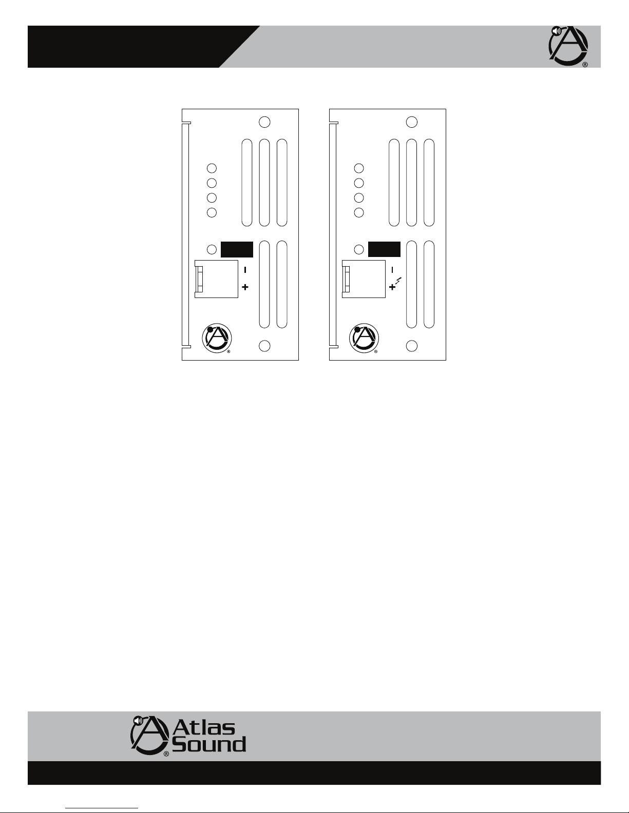
FM250-4 and FM250-70 Module Features
F6-MF
Multi-Impedance Modular Amplifier
FM250 -4
250W @ 4Ω
Protect
Limit
Signal
Ready
4 Ω
Speaker Output
Class 2 Wiring
FM250 -70
250W @ 70V
Protect
Limit
Signal
Ready
70V
Speaker Output
Class 2 Wiring
1. Module Status Indicators
Note: They also parallel Status LED on the front panel of the F6-MF panel.
Ready This LED will illuminate Green when an FM250 power module is installed on the appropriate channel and the F6-MF is
turned on.
Signal The channel Signal LED will illuminate Green when the FM250 amplifier output signal produces a minimum 1 Watt
output.
Limit The Limit LED will illuminate Yellow under load conditions. If the FM250 function switch is set to Limit then the LED
acts as a maximum level indicator. If the FM250 channel Limit function is off, the LED reacts as a Clip indicator. Also,
under Low Impedance loads, this LED serves as a current Limit indictor.
Protect The Protect LED will illuminate Red during one the following conditions. No output will occur while this LED is
illuminated. It will reset itself after the condition has been corrected.
1) Shorted speaker output.
2) Thermal Shut Off. The Temp F6-MF TEMP LED will also be illuminated.
3) Current Overdrive. If the amplifier channel is driving too low of a speaker load.
2. Speaker Connections
A removable Phoenix/Euro Block type connector is supplied to connect your speakers to the FM250 amplifier module. It is
recommended to use 16-gauge wire or lower for connection to the speakers. Note: Do not overload the amp by connecting too many
speakers to the amp.
1601 Jack McKay Blvd. • Ennis, Texas 75119 U.S.A.
Telephone: 800.876.3333 • Fax: 800.765.3435
– 9 – AtlasSound.com
Specifications are subject to change without notice.
F6-MF
Multi-Impedance Modular Amplifier
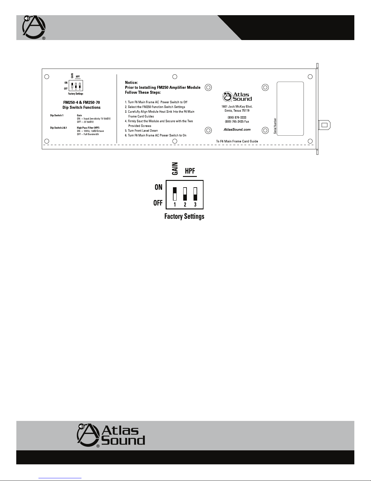
FM250-4 & FM250-70 Function Switch
Owner’s Manual
FM250 Module Dip Switch Functions are located near the rear of the FM250 modules. Note: It is essential to preset your setting prior
to inserting the module into the F6-MF.
Factory Dip Switch Presets
Dip Switch 1 ships in the “On” position. Dip Switches 2 & 3 ship in the “Off” position.
Dip Switch 1, Gain
When placed in the “On” position the channel’s Gain or Input Sensitivity will be 1V (0dBV) for rated output. When placed in the “Off”
position the Gain is set to 2V (6dBV).
Dip Switches 2 & 3, HPF
The High Pass Filter (HPF) when placed into the “On” position engages a 100Hz / 12dB filter. When in the “Off” position the module
operates at full audio bandwidth.
1601 Jack McKay Blvd. • Ennis, Texas 75119 U.S.A.
Telephone: 800.876.3333 • Fax: 800.765.3435
AtlasSound.com – 10 –
Specifications are subject to change without notice.
 Loading...