

Page 1
FAP82T
Installation Instructions
ATS001530 RevF 2/08
ATS001530 RevF 2/08
FAP82T
Installation
Instructions
Mounting
Template
14 1⁄8" Dia.
The Atlas Sound Strategy II Series® assembles and mounts easily
into existing construction drop ceiling or drywall materials.
Painting
Shield
13 3⁄4" Dia.
DROP TILE CEI LING INSTALLATION
1. Remove 2' x 2' or 2' x 4' tile.
2. Align the adju stable dual rail and C-ring assem bly on rear of t ile in desired pos ition.
3. Using template provide d; mark the cutout circle in the desired mounting location, 14" dia. mounting ho le.
4. Affix C-ring assembly to rails using screws provided and position ass embly on rear of ceiling tile.
Replace tile into gr id making sure that formed ends of t ile bridge rails engage T-bar tile suppor t rails.
5. Bring servi ce loop from rear of tile, through tile bridge C-ring to access panel located on side of enclosure.
Terminate the service loop to Phoenix style c onnector provided ( please note polarity) . Combination knoc kouts are
provided to facilitate co nduit. A UL rec ognized conduit conne ctor should be u sed to terminate conduit.
Connection cavity is not intended for use as a junc tion box.
6. Insert enclo sure through front of tile. Using standard #2 Phillips screwdriver or screw-gun, tighten
(4) dogleg assem blies until they engage C-ring assembly. DO NOT OVER-TIGHTEN DOG LEG SCREWS.
7. Adjust front mounted switch to desired wattage tap set ting or 8 Ω*. (See impor tant note regarding 8Ω operation)
8. Install press-fit grille into front bezel r ing. Push baffle upwards until baffle is flush with bezel ring.
9. For safety and seis mic considerations a suspension ring is integrated into input panel section of unit. Atlas Sound strongly suggests that
a support wire be installed from this support point to a suitab le anchor point above ceiling grid. In drop tile applic ations, this wire can
usually be installed from an adjacent t ile access near speaker location.
DRY WALL (“HARD DECK ”) INSTALLATION
1. Using template provided; mark the cutout cir cle in the desire d mounting location, 14" dia. mounting hole.
2. Place tile brid ge rails and C -ring through hole. Use V-shaped edge of C-ring to align tile bridge as sembly above ceiling
(alignment screws provided are not required for this type of installation)
3. Bring servi ce loop from rear of tile, through til e bridge C-rin g to access panel located on sid e of enclosure. Terminate the serv ice loop to
Phoenix style con nector provided (plea se note polarity). Combination knockouts are provided to facilit ate conduit. A UL recognized conduit connector
should be used to terminate conduit. Co nnection cavity is not intended for use as a juncti on box.
4. Insert enc losure into hole. Using standard #2 Phillips screwdriver or screw- gun, tighten (4) dog leg assemblies until they engage the C -ring assembly.
DO NOT OVER-TIGHTEN DOG LEG SCREWS.
5. Adjust front mounted switch to desired wat tage tap setting or 8 Ω*. (See impor tant note regarding 8 Ω operation)
6. Install press-fit grille into front bezel ri ng. Push baffle upwards until baffle is flush with bezel ring.
New Construction (Drywall Ceilings)
Use of optional FAP82-TR1 new constructio n bracket essentially reser ves speaker m ounting location prior to drywall installation in new c onstruction. The
bracket mounts between 16" or 24" OC studs and in cludes a 3⁄8" downward lip to provid e a template for dr ywall installers to cut around. For final installation,
please follow instructi ons below. Note: tile bri dge components are not used in new construction ap plications where new construction bracket is utilized.
1. Bring service loo p through hole in ceiling provided by pre construction bracket to access panel located on side of Enclosure.
Terminate service loop to Phoeni x style connec tor provided (please note polarity). C ombination knockouts are provided to facilitate c onduit.
2. Insert speaker assembly into hole. Usin g standard # 2 Phillips screwdriver or s crew-gun, tighten (4) dog leg assemblies until they engage ring provided
on new constructi on bracket. DO NOT OVER-TIGHTEN DOG LEG SCREWS.
3. Adjust front mounted switch to desired wattage tap setting or 8 Ω* (See imp ortant note regarding 8 Ω operation)
4. Install press-fit gr ille into front bezel ring. Push baffle upwards until baffle is flush with bezel ring.
NOTE: Dog legs will accommodate ceiling material thickne ss up to 1 1⁄4" as shipped from factory.
For thicker ceiling materials (up to 2") simply unscrew an d flip dog legs as shown.
DO NOT OVER-TIGHTEN DOG LEGS IN EITHER CONFIGURATION.
NOTE: *DO NOT USE 8 Ω SETTING WITH 70.7V/100V SYSTEMS.
*DO NOT OVERPOWER IN 8 Ω CONFIGURATION.
AMPLIFIER OUTPUT SHOULD NOT EXCEED
70 W RMS @ 8 Ω PER SPEAKER
1
FAP82-TR NOT TESTED OR EVALUATED BY UNDERWRITERS LABORATORIES (UL)
A UL RECOGNIZED CONDUIT CLAM P MUST BE USED FOR CONDUIT CONNECTIONS. CABLE CONNECTION CAVITY IS NOT INTENDED TO BE USED AS A JUNCTION BOX.
FREQUENCY RESPONSE: 80 Hz -20 kHz (± 5 dB)
SENSITIVITY: 89 dB (1 W/1 M)
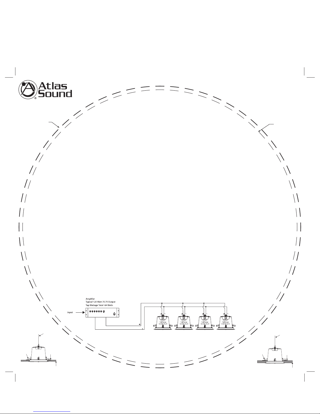
Typical Parallel Hookup of Full Range 70.7/100V Speakers
Auxiliary Suspension Point
Dog Leg
In Normal
Position
Tile Bridge
Ceiling Material up to 1 1⁄4
"
Auxiliary Suspension Point
Dog Leg
In Inverted
Position
Tile Bridge
Ceiling Material up to 2
"
 Loading...