

Page 1
Sound Masking Systems
by Ashton Taylor, Hoover & Keith Inc. for Atlas Sound
A technical guide to achieving effective
speech privacy in open-plan offices
and other environments
Page 2

INTRODUCTION
. . . . . . . . . . . . . . . . . . . . . . . 4
WHAT IS SOUND MASKING?
THE ECONOMIC BENEFITS OF SOUND MASKING 4
DEFINITION OF TERMS
(ALSO SEE APPENDIX A) . . . . . . . . . . . . . . . . . . 4
PURPOSE OF THIS PAPER . . . . . . . . . . . . . . . . . . 4
PART 1 - A DISCUSSION OF
SOUND MASKING
APPLICATIONS FOR SOUND MASKING SYSTEMS . 5
Open-Plan Offices . . . . . . . . . . . . . . . . . . . . . . 5
Medical Examination Rooms . . . . . . . . . . . . . 5
Confidential Offices . . . . . . . . . . . . . . . . . . . . . 5
Court Rooms . . . . . . . . . . . . . . . . . . . . . . . . . . 5
Buildings near Major Roads, Railroads,
& Airports . . . . . . . . . . . . . . . . . . . . . . . . . . . . . . . . . . 6
Personal Masking Units . . . . . . . . . . . . . . . . . 6
Security Systems . . . . . . . . . . . . . . . . . . . . . . . 6
WHEN SOUND MASKING SHOULD NOT BE USED . . 6
Unrealistic Client Expectations . . . . . . . . . . . 6
Rooms Requiring Very Low Ambient Noise . . 6
Space Used by Sight-Impaired People . . . . . . 6
Space Used by Hearing-Impaired People . . . . 6
BENEFITS OF MASKING TO THE END USER . . . 7
Cost-Effective Speech Privacy . . . . . . . . . . . . 7
Increased Productivity . . . . . . . . . . . . . . . . . . 7
Flexibility . . . . . . . . . . . . . . . . . . . . . . . . . . . . . 7
PART 2 - THE SOUND MASKING
ACOUSTICAL ENVIRONMENT
THREE STEPS TO SUCCESSFUL SOUND MASKING
1 - Attenuate the Direct Sound . . . . . . . . . . . . 8
2 - Reduce Sound Reflections . . . . . . . . . . . . . 8
3 - Raise the Ambient Sound Level
Using Sound Masking . . . . . . . . . . . . . . . 8
Discussion . . . . . . . . . . . . . . . . . . . . . . . . . . . . 8
A BASIC SOUND MASKING EXAMPLE . . . . . . . . 8
EVALUATING THE ACOUSTICAL ENVIRONMENT . . . 9
ATTENUATION OF DIRECT SOUND . . . . . . . . . . 9
Orientation of Talker . . . . . . . . . . . . . . . . . . . .10
Screens . . . . . . . . . . . . . . . . . . . . . . . . . . . . . .10
Sound Transmission Class . . . . . . . . . . . . . . .10
Diffraction . . . . . . . . . . . . . . . . . . . . . . . . . . . .11
Layout . . . . . . . . . . . . . . . . . . . . . . . . . . . . . . .12
REDUCTION OF REFLECTED SOUND ENERGY 13
Ceiling . . . . . . . . . . . . . . . . . . . . . . . . . . . . . . .13
Absorption Ratings . . . . . . . . . . . . . . . . . . . . .13
Noise Reduction Coeffcient . . . . . . . . . . . . . . .13
Articulation Class . . . . . . . . . . . . . . . . . . . . . .13
Lighting Fixtures . . . . . . . . . . . . . . . . . . . . . . .14
MASKING LOUDSPEAKERS AND THE CEILING .14
Special ceiling tiles . . . . . . . . . . . . . . . . . . . . .14
Sound leaks . . . . . . . . . . . . . . . . . . . . . . . . . . .14
Boots . . . . . . . . . . . . . . . . . . . . . . . . . . . . . . . .15
OTHER CAUSES OF UNWANTED
REFLECTIONS . . . . . . . . . . . . . . . . . . . . . . . .15
AMBIENT NOISE . . . . . . . . . . . . . . . . . . . . . . . . . .17
PART 3 - THE BASIC ELECTRONIC
SOUND MASKING SYSTEM
CONCEPT . . . . . . . . . . . . . . . . . . . . . . . . . . . . . . .18
Don’t Tell the Employees? . . . . . . . . . . . . . . .18
Self-Contained Masking Units . . . . . . . . . . . . . . .18
Single-Channel vs Multi-Channel Masking . .18
Basic Electronics . . . . . . . . . . . . . . . . . . . . . . .18
SOUND MASKING AND BACKGROUND MUSIC
OR PAGING . . . . . . . . . . . . . . . . . . . . . . . . . . .19
BASIC SYSTEM ELECTRONICS . . . . . . . . . . . . . .19
Masking Sound Generator . . . . . . . . . . . . . . .19
Equalizer . . . . . . . . . . . . . . . . . . . . . . . . . . . . .20
Amplifier . . . . . . . . . . . . . . . . . . . . . . . . . . . . .20
PART 4 - MULTI-CHANNEL MASKING,
BACKGROUND MUSIC AND PAGING
TWO (AND MORE) CHANNEL MASKING . . . . . .21
Zone Level Controls . . . . . . . . . . . . . . . . . . . .22
Amplified Monitor Panel . . . . . . . . . . . . . . . . .22
BACKGROUND MUSIC . . . . . . . . . . . . . . . . . . . . .22
PAGING . . . . . . . . . . . . . . . . . . . . . . . . . . . . . . . . .22
Paging Sound Level . . . . . . . . . . . . . . . . . . . . .23
Paging Equalizers . . . . . . . . . . . . . . . . . . . . . .23
Part 1
Index
Page 3

PART 5 - MASKING LOUDSPEAKERS
AND SELF-CONTAINED MASKING UNITS
MASKING LOUDSPEAKERS . . . . . . . . . . . . . . . . .24
Upwards Loudspeaker Orientation . . . . . . . .24
Downwards Loudspeaker Orientation . . . . . .25
Horizontal (Sideways)
Loudspeaker Orientation . . . . . . . . . . . . . . .25
In-Ceiling Placement . . . . . . . . . . . . . . . . . . .25
Valuable Masking Loudspeaker Features . . .25
SELF-CONTAINED MASKING UNITS . . . . . . . . . .26
PART 6 - COMMISSIONING THE
MASKING SYSTEM
LEVEL . . . . . . . . . . . . . . . . . . . . . . . . . . . . . . . . . .27
Connecting Spaces . . . . . . . . . . . . . . . . . . . . .27
Setting the Level During System Adjustment 27
Gradually Adjust to Final Level . . . . . . . . . . .27
MASKING SPECTRUM . . . . . . . . . . . . . . . . . . . . .28
Ideal Masking Sound Spectrum . . . . . . . . . . .28
Masking Spectrum 1 . . . . . . . . . . . . . . . . . . . .28
Masking Spectrum 2 . . . . . . . . . . . . . . . . . . . .29
Masking Spectrum 3 . . . . . . . . . . . . . . . . . . . .29
A Comparison of All Three Masking Spectra .30
EQUALIZING THE SYSTEM . . . . . . . . . . . . . . . . .30
The Equalization Process . . . . . . . . . . . . . . . .30
Using an Octave-Band Equalizer for . . . . . . .
Troubleshooting . . . . . . . . . . . . . . . . . . . . . . .31
COVERAGE . . . . . . . . . . . . . . . . . . . . . . . . . . . . . .31
TEST EQUIPMENT . . . . . . . . . . . . . . . . . . . . . . . .31
PART 7 - PREDICTING PRIVACY IN THE
MASKING ENVIRONMENT
. . . . . . . . . . . .32
ARTICULATION INDEX AND PRIVACY
CATEGORY DEFINITIONS . . . . . . . . . . . . . . . . .32
Marginal Privacy . . . . . . . . . . . . . . . . . . . . . . .32
Normal Privacy . . . . . . . . . . . . . . . . . . . . . . . .33
Confidential Privacy . . . . . . . . . . . . . . . . . . . .33
Total Privacy . . . . . . . . . . . . . . . . . . . . . . . . . .33
PREDICTING SPEECH PRIVACY . . . . . . . . . . . . . .33
PART 8 - CASE HISTORIES
MASKING IMPROVES SPEECH PRIVACY
IN A QUIET SPACE . . . . . . . . . . . . . . . . . . . . . . .34
BOOTS REDUCE HOT SPOTS PROBLEM . . . . . .34
PROBLEMS RESULTING FROM UNINSTALLED
BOOTS . . . . . . . . . . . . . . . . . . . . . . . . . . . . . . . . . .34
LEAKY LUMINAIRES CAUSE HOT SPOTS . . . . . .34
MASKING LOUDSPEAKERS TAPPED TOO LOW
. .35
COMPLICATED SYSTEM . . . . . . . . . . . . . . . . . . .35
MEDICAL SUITE MASKING TEST . . . . . . . . . . . .35
MEDICAL PROFESSIONAL BUILDING MASKING
.36
MASKING IMPROVES PRIVACY IN A
PASTOR’S OFFICE . . . . . . . . . . . . . . . . . . . . . . .36
MASKING AND UNWANTED REFLECTIONS
IN A PSYCHIATRIST’S OFFICE . . . . . . . . . . . . .36
CONCLUSION
. . . . . . . . . . . . . . . . . . . . . . . . . .37
APPENDIX A - DEFINITIONS
. . . . . . . . . .38
APPENDIX B - WORKSHEET
. . . . . . . . . .40
GENERAL INSTRUCTIONS . . . . . . . . . . . . . . . . . .40
Entering the Data . . . . . . . . . . . . . . . . . . . . . .40
Calculating the Speech Level at the Listener 40
Calculating the Articulation Index . . . . . . . . .40
DETAILED WORKSHEET INSTRUCTIONS
Section A Instructions . . . . . . . . . . . . . . . . . . .41
Section B Instructions . . . . . . . . . . . . . . . . . . .41
Section C Instructions . . . . . . . . . . . . . . . . . . .42
Section D Instructions . . . . . . . . . . . . . . . . . . .43
Section E Instructions . . . . . . . . . . . . . . . . . . .44
Section F Instructions . . . . . . . . . . . . . . . . . . .45
Section G Instructions . . . . . . . . . . . . . . . . . . .45
Section H Instructions . . . . . . . . . . . . . . . . . . .46
Section I Instructions . . . . . . . . . . . . . . . . . . .46
Section J and Section K Instructions . . . . . . .47
Section L Instructions . . . . . . . . . . . . . . . . . . .47
SOUND-MASKING, OCTAVE-BAND,
ARTICULATION- INDEX WORKSHEETS
WORKSHEET EXAMPLE 1 -
OPEN-PLAN ENVIRONMENT . . . . . . . . . . . . .48
Part 1 - No Speech Privacy . . . . . . . . . . . . . . .48
Part 2 - Add Masking Sound . . . . . . . . . . . . . .48
Part 3 - Substitute 6-Foot-High Partition
Screens . . . . . . . . . . . . . . . . . . . . . . . . . . . . .49
Part 4 - Move Workstations Farther Apart . . .49
Part 5 - Install a High Articulation Class
(AC) Ceiling . . . . . . . . . . . . . . . . . . . . . . . . .50
Summary and Conclusions . . . . . . . . . . . . . . .50
WORKSHEET EXAMPLE 2 - A WALLED SPACE
Part 1 - No Masking Sound . . . . . . . . . . . . . . .51
Part 2 - Add Masking Sound . . . . . . . . . . . . . .51
Summary . . . . . . . . . . . . . . . . . . . . . . . . . . . . .52
No part of this white paper may be copied or used without the written permission of Atlas Sound.
© 2000 Atlas Sound
Page 4

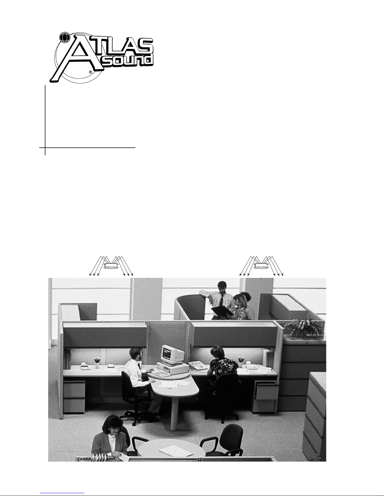
A sound masking system emits low-level,
non-distracting masking noise designed to
reduce speech intelligibility and thereby
improve speech privacy. This improvement
in speech privacy can be of great value in
open-plan offices, doctors’ examination
rooms and other environments where confidentiality is important.
Sound masking can also reduce the distraction caused by traffic, office machinery and
other unwanted sounds. Because this benefit is limited to situations where the unwanted sounds are of relatively low level, however, speech privacy is the focus of most
sound masking systems.
A typical sound masking system consists of
a masking noise generator, an equalizer,
one or more power amplifiers and a group
of special loudspeakers installed above a
dropped ceiling. Well-designed room
acoustics are an important component of a
successful masking system.
The Economic Benefits
of Sound Masking
The economic benefits of sound masking
vary from application to application but can
be significant. Consider a large insurance
company selling life insurance over the telephone. Many times each day, an agent will
ask a prospective client for financial and
health information. The insurance company must maintain a reasonable degree of
confidentiality for this kind of information.
Yet, if the agents work in a traditional open
office environment, the lack of speech privacy makes it nearly impossible to achieve
this goal.
One way to provide speech privacy would
be to construct a private office for each
agent. Yet, as anyone who has ever slept in
a cheap motel room knows, even doors and
walls do not guarantee privacy! A truly
“private” office must include sound insulating walls, sealed doors and baffles in the
air-handling ducts — not a low-cost
solution.
A lower cost solution is an open plan office
with well-designed acoustics and a sound
masking system. This kind of environment
can achieve normal speech privacy while
maintaining the flexibility of the open plan
office. As a side benefit, the sound masking
system will reduce the distraction of
unwanted sounds like office machinery and
traffic, enabling the insurance agents and
other office workers to maintain a higher
level of productivity.
Purpose of this Paper
This paper discusses the acoustics and electronics of a successful sound masking system and provides case histories as illustrations. Appendix A contains definitions of
sound masking and acoustical terms.
Appendix B is a useful sound masking worksheet that can help estimate the degree of
privacy achievable in a new or retrofitted
system.
Although it is detailed and accurate, this
paper cannot make the reader into a sound
masking expert. For this reason, Atlas
Sound recommends that architects, building
owners and systems contractors seek the
assistance of a qualified acoustical consultant when contemplating the design and
installation of a sound masking system.
Introduction and Executive Summary
What is Sound Masking?
Page 4
Page 5

Applications for Sound Masking
Systems Open-Plan Offices
Definition of Terms
(also see Appendix A)
In this paper, the term “talker” refers to a
person. The term “speaker” refers to a loudspeaker. The term “listener” refers to anyone
hearing sounds, whether or not they intend to
hear those sounds.
“Marginal”, “normal” and “confidential”
speech privacy are subjective terms that are
discussed more completely in the section
entitled “Predicting Privacy in the Masking
Environment”. In general, however, “marginal” refers to an unacceptable level of
speech privacy. “Normal” speech privacy is
acceptable for open-plan office environments. “Confidential” speech privacy is
desirable for confidential conference rooms,
psychiatrist’s and lawyer’s offices and other
highly confidential environments. Modern
open-plan office environments function as a
group of independent offices in a single
large open space. Movable screens between
offices act as both acoustical and visual barriers. Sound masking completes the environment by adding speech privacy.
Compared to the completely open “typing
pool” concept, each employee has a comfortable working zone with both visual and
speech privacy.
Medical Examination Rooms
Medical examination rooms are often small
(perhaps 100 square feet) and close together. The low-cost construction used for these
rooms provides walls and doors for visual
privacy but offers very limited speech privacy.
In fact, it is not uncommon to hear and
understand every word of a conversation
between a doctor and patient in adjacent
examination rooms! This can be very
inhibiting for the patients. Sound masking
can create effective speech privacy in these
rooms at a lower cost than construction
improvements alone.
Confidential Offices
Psychiatrists, lawyers, law enforcement personnel and marriage or school counselors
all require confidential privacy in their
offices. This privacy can be achieved with
construction techniques alone. However,
the required sound isolating walls, doors,
and windows can be very expensive. The
alternative of sound masking, in conjunction with less costly construction techniques, can achieve the required privacy at
a lower overall cost.
Some environments, such as psychiatrists’
offices, may require an extremely high
degree of privacy. Other situations, in existing structures, may involve significant
acoustical problems or building layout
issues. In these cases, Atlas Sound recommends the services of a qualified acoustical
consultant.
Court Rooms
Sound masking can be useful in a courtroom when the judge needs to have a
private conference with lawyers and
prosecutors at the bench. Equip the judge’s
microphone with a mute switch that also
engages sound masking through loudspeakers located over the audience and the jury.
Part 1
A Discussion of Sound Masking
Page 5
Page 6

Buildings near Major Roads,
Railroads, and Airports
In most buildings, it is not feasible to completely mask higher-level noises like those
from heavy trucks, trains, or aircraft.
However, sound masking can soften the
impact of these noises. If a client wants
masking to cover up these sounds, make
sure their expectations are not too high. In
most cases, the intruding sounds will still be
audible after masking is installed. However,
masking will minimize the startle effect
because the sound level changes less.
Personal Masking Units
Personal masking units, which are commonly sold as sleep aids, offer a selection of
masking sounds and other pleasant sounds
like breaking surf, babbling brooks, train
clickity-clack, rain, waterfall, and church
bells. Do not confuse these units with the
self-contained masking units (described
later in this paper) which are designed for
professional use in offices. Other than this
brief discussion, personal masking units are
not covered in this paper.
Security Systems
Specialized masking systems emit high
intensity masking sound outside the windows and doors of top-secret conference
rooms in buildings that require extremely
high levels of security. These systems are
not covered in this paper.
When Sound Masking
Should Not Be Used
Unrealistic Client Expectations
A successful masking system requires careful
coordination of an acoustical ceiling, office partition screens, absorptive furniture, overall
building acoustics and the electronic sound
masking system. Yet, some clients, having
heard about a “miracle” at another facility, may
expect electronic sound masking alone to solve
their problems.
Educate these clients about the limits of sound
masking and about the acoustical and construction requirements. If the client is unwilling to
make necessary acoustical or construction
improvements, tell them clearly that only the
electronic functionality of the system is guaranteed, not the acoustical results.
Rooms Requiring
Very Low Ambient Noise
The acoustic echo cancellers, used in audio
and video teleconferencing systems, work
best in rooms with very low ambient noise.
Thus, masking sound is not a good way to
maintain voice privacy or to mask unwanted
noises in teleconferencing rooms or in other
environments which require very low ambient noise. Instead, retain a qualified
acoustical consultant to help with acoustical
solutions.
Space Used by Sight-Impaired People
Masking sound and an absorbent environment can hide the aural clues used by the
visually impaired to sense their immediate
surroundings.
Space Used by Hearing-Impaired People
Masking sound can impair the ability of
people with acute hearing loss to understand speech, especially in situations where
face-to-face communication is not possible.
Page 6
Page 7

Benefits of Masking
to the End User
Cost-Effective Speech Privacy
Normal (not confidential) privacy can usually be achieved with floor-to-ceiling walls
between workspaces. However, sound
masking allows normal privacy to be
achieved in an open-plan office with simple
partitions between cubicles. This is a costeffective solution that allows a building
owner or leasee to retain the flexibility of an
open-plan office.
Confidential privacy, without sound masking, requires multiple-layer walls, from the
floor to the deck above the ceiling, combined with special sound-isolation doors,
door seals and careful caulking of all penetrations of the wall to stop sound leaks.
This kind of construction can be very costly.
In contrast, masking sound allows confidential privacy to be achieved with normal
building partitions that extend from floor to
ceiling.
Increased Productivity
Without sound masking, employees in an
open-plan office must deal with constant
audible distractions, including office
machinery noises, traffic noises and clearly
heard conversations from adjacent workspaces. Even when working in a private
office, employees may hear noises and conversations coming from adjoining offices or
hallways.
With sound masking, these noises will be
less irritating and the conversations, while
still audible, will be unintelligible and
therefore much less distracting.
Flexibility
Without sound masking, the open-plan
office is little more than an old-fashioned
typing pool with partitions. Noises and
clearly audible conversations from nearby
cubicles distract workers and limit their
productivity. Lack of speech privacy may
even inhibit some employees from performing necessary job functions.
With sound masking, the open office gains
the speech privacy of individual private
offices yet retains the flexibility of the openplan concept. Just move partitions to add or
delete offices, combine offices into a conference area or to create an open space for use
as a break-room or file-room area. In most
cases, lighting and air ducts, which are
located in the ceiling, need not be moved.
Also, in a well-planned open-office space,
it’s easy to reconfigure electrical, telephone,
fax and computer connections.
Page 7
Page 8

Three Steps to Successful
Sound Masking
Carefully planned acoustics, combined with
masking sound, make it possible to achieve
the goal of increased speech privacy
between workstations.
There are three steps to successful
sound masking:
1.
Attenuate the Direct Sound
“Direct sound” from a talker reaches a
listener by the shortest path without
being reflected by any object.
2.
Reduce Sound Reflections
Reflected sound from a talker reaches a
listener after being reflected from one or
more hard objects.
3.
Raise the Ambient Sound Level Using
Sound Masking
Sound masking adds low-level background
noise to reduce the speech-to-noise ratio
and reduce intelligibility.
Discussion
It’s not always necessary to take all three
steps to achieve a desired level of speech
privacy. In private offices, for example,
floor-to-ceiling walls may attenuate the
direct sound enough to achieve normal
speech privacy.
In open-plan offices, however, even normal
speech privacy requires all three steps. Use
absorptive furniture and screens (partitions)
to attenuate the direct sound and reduce
unwanted reflections. Use acoustical ceil-
ings to further reduce reflections between
adjacent office spaces. Sound masking
completes the job by adding a low level of
random electronic noise to mask the
remaining unwanted sounds.
In effect, the first two steps, which involve
acoustics alone, reduce the level of unwanted sound. The last step, adding masking
noise, masks the remaining unwanted
sound in such a way as to create speech privacy and reduce distractions.
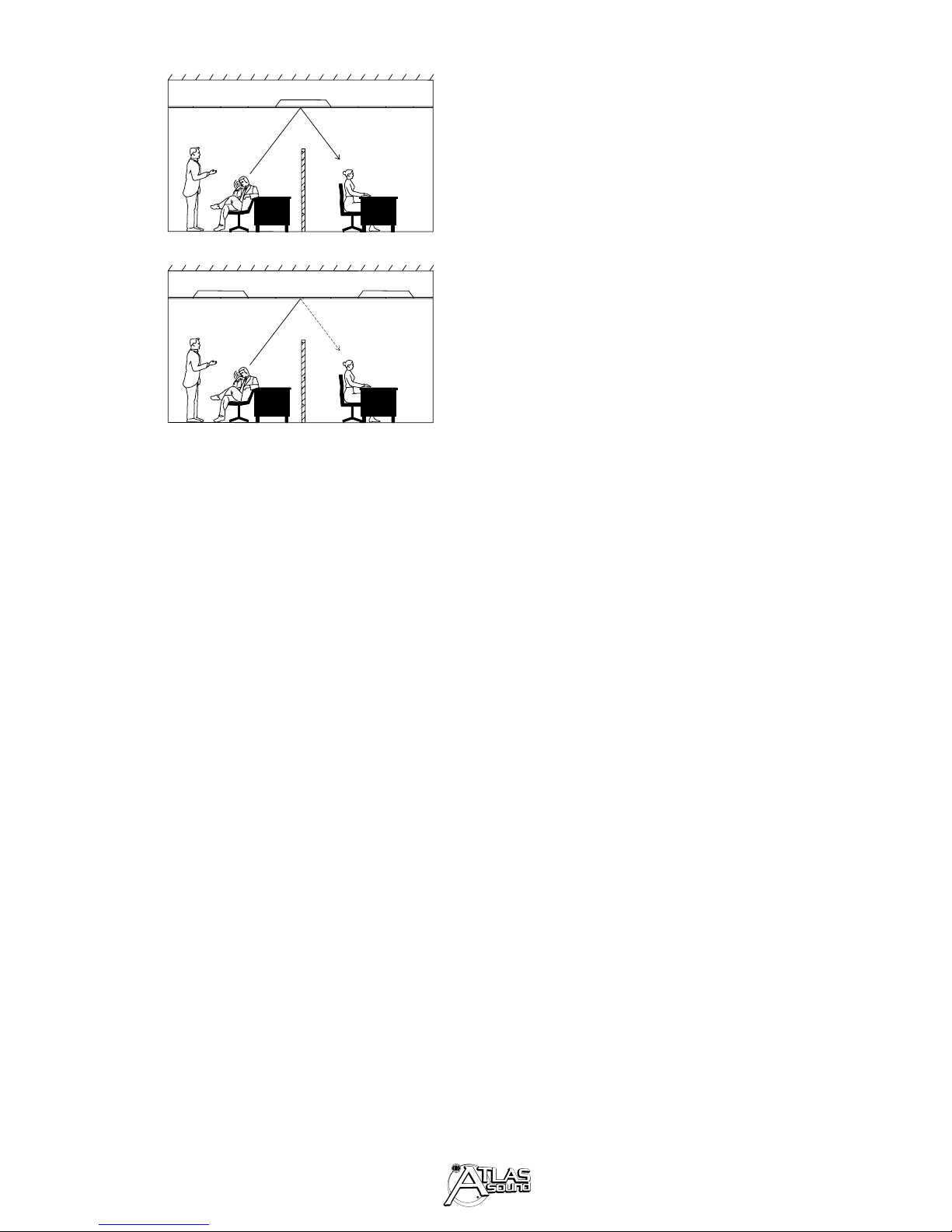
A Basic Sound Masking Example
Figure 1 illustrates these concepts. Part A
shows a poorly-designed open-plan office
environment. There is no barrier to reduce
the direct sound level between the talkers
and the listener, the hard ceiling reinforces
the direct sound with reflections, and the
low level of background sound does not
mask the speech. The dashed line represents the level (as a graph) of speech and
the dotted line represents the room or background sound level. Notice that the room
level is much lower than the speech level.
In Part B, the screen attenuates direct
sound, an absorptive ceiling reduces reflected sound energy, and the masking loudspeakers in the ceiling plenum add masking
sound. The result is effective (normal)
speech privacy.
Figure 2 introduces the concept of sound
masking in octave bands. The solid line in
Part A shows the octave-band sound levels
of a talker as heard at a nearby workstation.
The dotted line in Part A shows quiet back
Part 2
A Discussion of Sound Masking
Page 8
Page 9
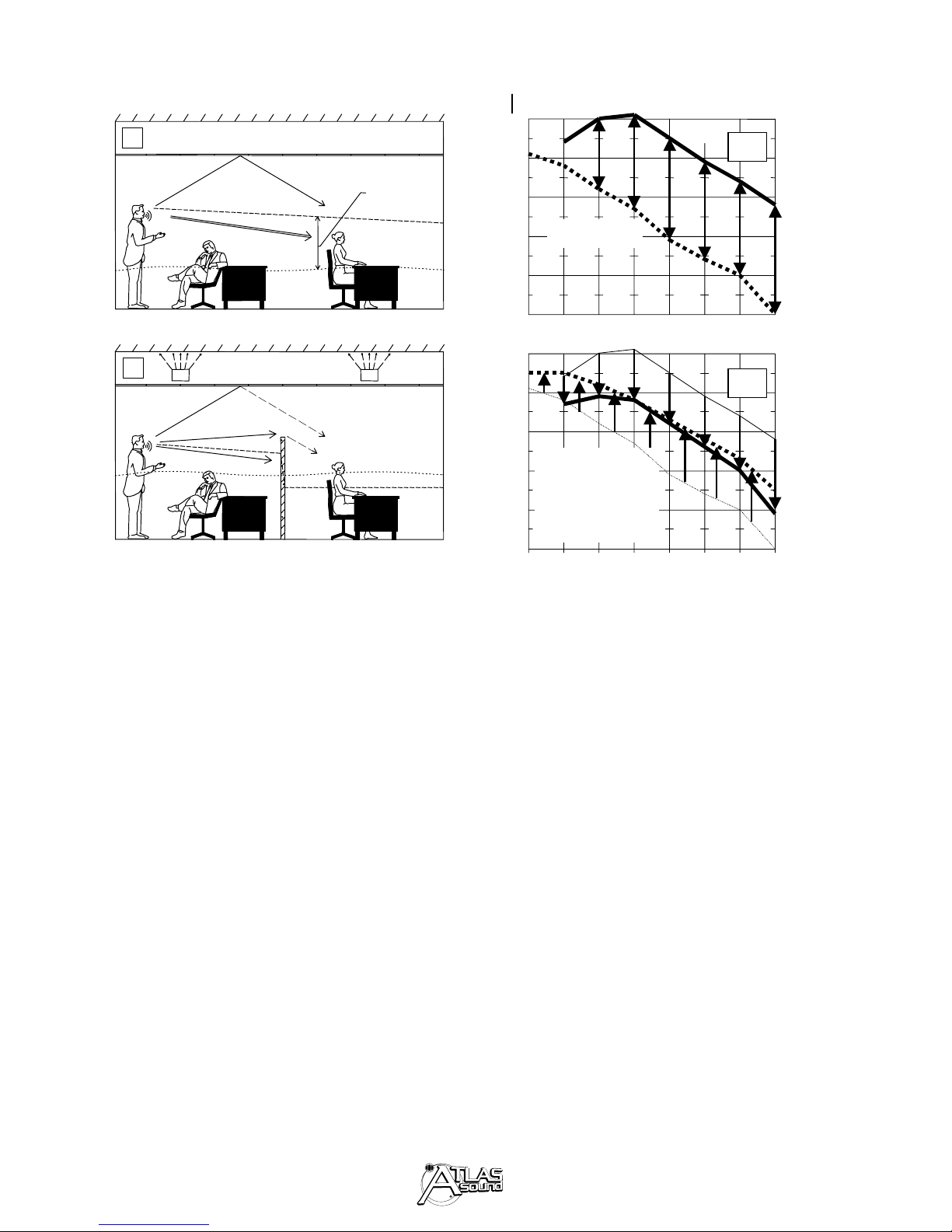
ground sound levels typical in an open-plan
office. Thus, Part A shows a high speech-tonoise ratio in every octave band resulting in
high articulation and no speech privacy.
Part B shows a lower speech-to-noise ratio
and a more desirable level of speech privacy
achieved with partitions, absorptive surfaces
and masking sound.
Evaluating the Acoustical Environment
In existing spaces, it may not be possible to
improve the acoustics by installing absorptive
partitions and furnishings, improving the ceiling or applying new interior finishes. In new
spaces, the building owner or lessee may have
very specific ideas about building decor which
limit the ability to optimize the
acoustics.
It is always important, however, to be able
to evaluate the acoustical environment and
provide advice to a prospective client. The
acoustical information in this section and
the worksheet in Appendix B are designed
to aid that process and help avoid some
common pitfalls. Again, a qualified acoustical consultant can help when an evaluation
suggests that problems are inevitable.
SOUND PRESSURE LEVEL re 20 µPa,
FIG. 2 - This two-part graph illustrates the concept of sound masking by showing octave-band
sound levels of a talker and background sound
before (Part A) and after (Part B) acoustical
improvements and sound masking are installed.
Page 9
FIG. 1 - In Part A, direct sound from the talker
and reflected sound off a hard ceiling contribute to poor speech privacy. In Part B, an
absorptive ceiling and screen reduce the direct
and reflected sound level, and masking sound
provides effective (normal) speech privacy.
dB
60
A
50
Reflected
Sound
Speech-
to-Noise
Ratio
40
Talker
A
Direct
Sound
B
Masking Loudspeakers
Speech Sound
Level
Room
Sound
Level
Room Sound
Level
Speech
Sound
Level
30
20
10
60
50
40
30
20
10
Background
1000 2000 4000 8000250 50063 125
Talker sound:
Reduced level
Background sound:
Raised level
1000 2000 4000 8000250 50063 125
OCTAVE-BAND CENTER FREQUENCY,
Hz
B
Page 10
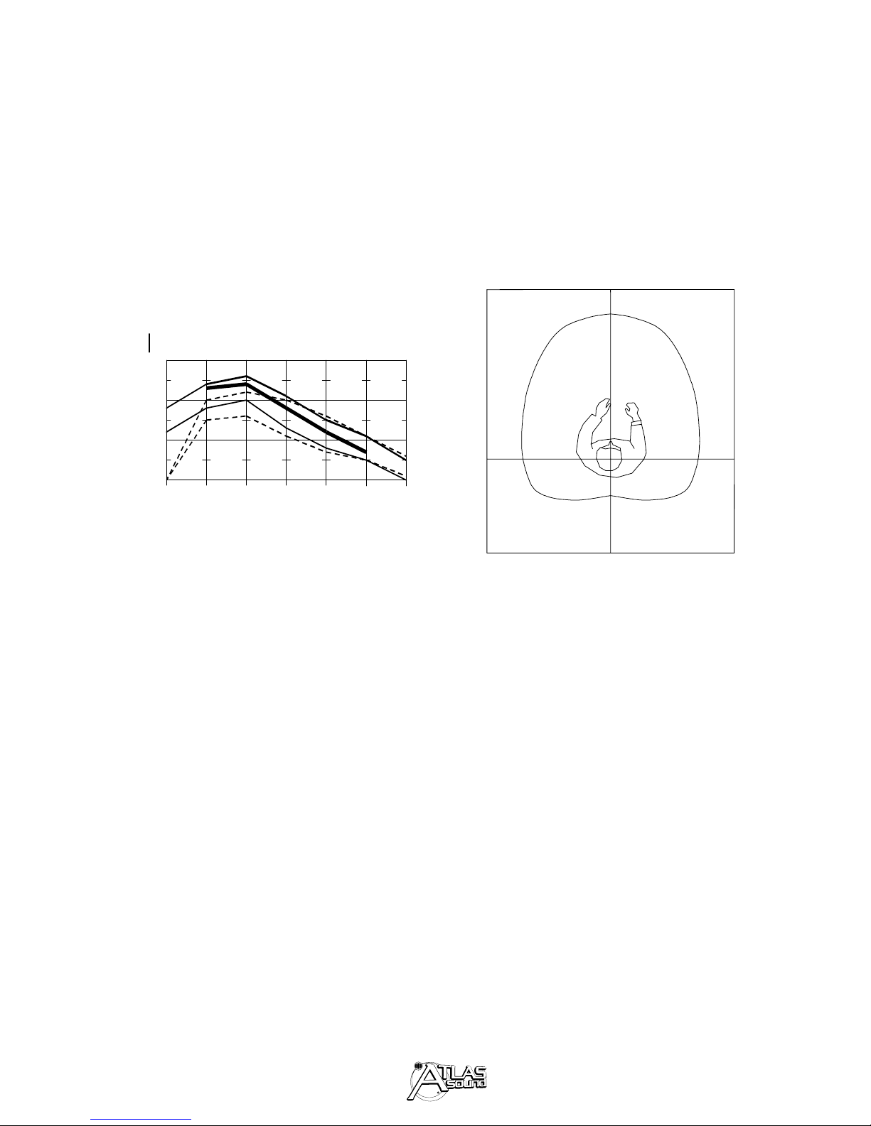
Attenuation of Direct Sound
The direct sound is speech from a talker
that arrives directly at the ear of a listener
without being reflected. Figure 3 shows the
direct peak sound levels for male and
female talkers at a distance of one meter.
FIG. 3 - Octave-band speech peak sound levels
for male and female talkers at a distance of 1
meter. The solid curves are for male talkers
with normal (lower curve) and raised voices
(upper curve). The dashed lines are for female
talkers with normal and raised voices. The
heavier solid curve is the ANSI S3.5 standard
voice level.
Orientation of Talker
Speech sound level varies as a talker turns
away from a listener. Speech levels are
highest during face-to-face conversation
where the talker is “on axis” (0∞) with the
listener. As the talker turns away, the Aweighted sound level at the listener is
reduced by approximately 1.5 dB for each
30
º
( the talker is off axis from the listener
(see Figure 4).
The head orientation of the listener with
respect to the talker makes little difference
in terms of received level, and is therefore
unimportant in sound masking calculations.
For speech privacy calculations, assume
that the talker is on-axis with the listener
(worst case) unless the talker/listener orientation is fixed.
FIG. 4 - This polar plot shows the relative level
from a talker versus angle. The speech level at a
listener’s position decreases by approximately
1.5dB for every 30º the talker is off-axis from
the listener. The orientation of the listener’s
head is unimportant in speech level calculations.
Screens
The partitions between work areas in an
open-plan office are called screens.
Because these screens function as sound
barriers, they must be designed to attenuate
the sound passing through them and they
must be tall enough to provide a barrier to
sound passing over them. Finally, screens
must be absorptive enough to prevent sound
build-up within each workstation. Figure 5
illustrates these concepts.
Page 10
SOUND PRESSURE LEVEL re 20 µPa,
dB
80
70
60
50
4000
8000125 250
2000
1000
500
OCTAVE-BAND CENTER FREQUENCIES,
Hz
0°
90°
180°
90°
Page 11
Sound Transmission Class
Sound transmission class (STC) is a standard
way to specify the attenuation of sound through
a wall, an open-plan office screen or other barrier. A higher STC is better. A screen with a
high STC rating will attenuate the sound more
than a screen with a low
STC rating.
STC values for typical gypsum board office
walls are 30 - 35. Very thick and massive
wall constructions may have STC values of
60 or more. Open-plan office screens
should have an STC value of at least 20.
However, once the STC exceeds 25, the
sound passing over the screen becomes the
limiting factor. Thus, most commercially
available screens have STC ratings between
20 and 30.
Diffraction
Even if the ceiling is non-reflective, sound
can pass above a screen by a process known
as “diffraction”. Lower-frequency sounds
will diffract over a screen of a given height
more easily than higher-frequency sounds.
Fortunately, the higher-frequency sounds
are the most important for speech privacy
and this suggests that a screen higher than
a tall person’s mouth level should be high
enough to block diffraction of the most
important speech frequencies.
Following this line of thinking, a 4-foot high
barrier, which is barely above the level of a
seated person’s mouth, provides only marginal attenuation between workstations, a
5-foot high barrier provides adequate
attenuation if the ceiling and walls are very
absorptive, and a 6-foot high barrier usually
provides good attenuation.
For best results, the screen should be at
least 3 times as wide as it is high although
that implies 15-foot to 18-foot cubical widths
which is often impossible. Ideally, the
bottom of the screen should make direct
contact with the floor. The maximum
acceptable gap along the bottom of a screen
is 1 inch.
Screens must be absorptive to prevent
sound build-up in an individual workspace.
A workspace surrounded by absorptive
screens can be 5 to 6dB quieter than a hardsurfaced work area. However, screens can
have their upper surface (no more than the top
1-foot) made of glass for visual openness.
(a)
Page 11
FIG. 5 - Screens should (a) be high enough to
reduce sound passing over them, (b) provide a
good barrier to sounds passing through them,
and (c) absorb incident sound.
(b)(c)
Screen
6′ high
Page 12
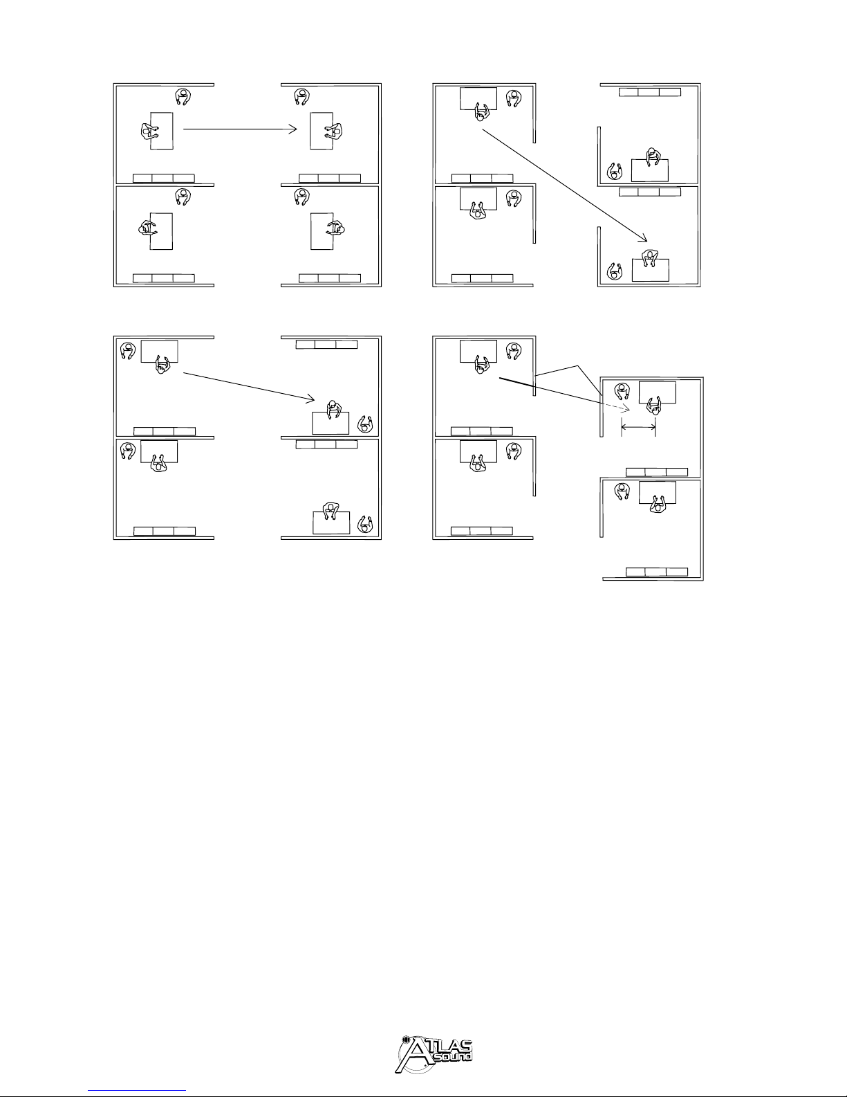
Layout
Simple layout changes can often improve
speech privacy in an open-plan office. And,
even though these changes will disrupt
daily routine in an existing space, clients
with severe privacy problems are usually
willing to comply. In general, an effective
layout means avoiding these problems:
* Adjacent workstations closer than 10 feet
(16 feet preferred)
* Workstation openings directly across from
each other (line of sight)
* Side-by-side openings of two adjacent
workstations
* Desks facing each other on each side of a
screen (see page 12).
* Openings near windows or building
curtain wall (external perimeter)
* Openings to a common corridor or other
area with an opposite hard wall
Figure 6 shows poor and improved layouts
for open-plan workstations.
POOR LAYOUTS IMPROVED LAYOUTS
FIG. 6 - Examples of good and bad layouts for workstations in open-plan spaces.
Reduction of Reflected Sound Energy
Page 12
Direct, uninterrupted
path (talkers face each
other)
Longer
uninterrupted
path
Only
uninterrupted
path
Screens (to interrupt
path to opposite
workstation)
Separation distance,
6 ft.
PLAN VIEW
Page 13

Ceiling
The ceiling in an open-plan office affects
speech privacy more than any other acoustical element. A hard ceiling reflects sound
from one workstation to another, bypassing
the sound barrier provided by the workstation screens. This problem is worse when
the angle of reflection is between 40º and
60º. For this reason, open-plan offices
should always have absorptive ceilings.
Absorption Ratings
The unit of absorption is the sabin. One
“sabin” (in the US customary measurement
system) is equal to one square foot of perfect (total) absorption. We often think of
this as one square foot of an open window.
“Absorption coefficients” rate the absorptivity of a surface between 0.00 (perfect reflector) and 1.00 (perfect absorber) and are
written as two-decimal numbers.
Specifications for typical interior finish
materials provide absorption coefficients in
octave bands. Absorption coefficients higher than 1.00 are sometimes given for very
highly absorptive materials. This is an artifact of the testing procedure since it is
impossible to absorb more than 100% of the
incident sound.
Noise Reduction Coeffcient
Ceiling tile absorption is rated with an
acoustical descriptor called the “noise
reduction coefficient” (NRC) which is an
average of the absorption coefficients of the
250-Hz, 500-Hz, 1000-Hz, and 2000-Hz
octave bands, rounded to the nearest 0.05.
Typical 3/4-inch thick mineral fiber ceiling
tile has an NRC value between 0.50 and 0.70
but normal speech privacy in open-plan
office environments commonly requires
1-inch thick compressed fiberglass ceiling
tiles with an NRC value of 0.90 or more.
Articulation Class
“Articulation Class” (AC) is a new rating for
acoustical performance. A material’s articulation class rating is the sum of the attenuations (in dB) of the 15 third-octave bands
from 200 Hz to 5000 Hz.
Articulation class is measured between a
source (talker) workstation and a receiver
(listener) workstation in an actual openplan office space. Because it measures
effectiveness in real-world conditions, articulation class is the preferred rating method
for ceiling tile. Select ceiling tile products
with AC ratings of 200 or more for openplan offices. If a ceiling tile product does
not have an AC rating, use the NRC rating.
Page 13
Page 14
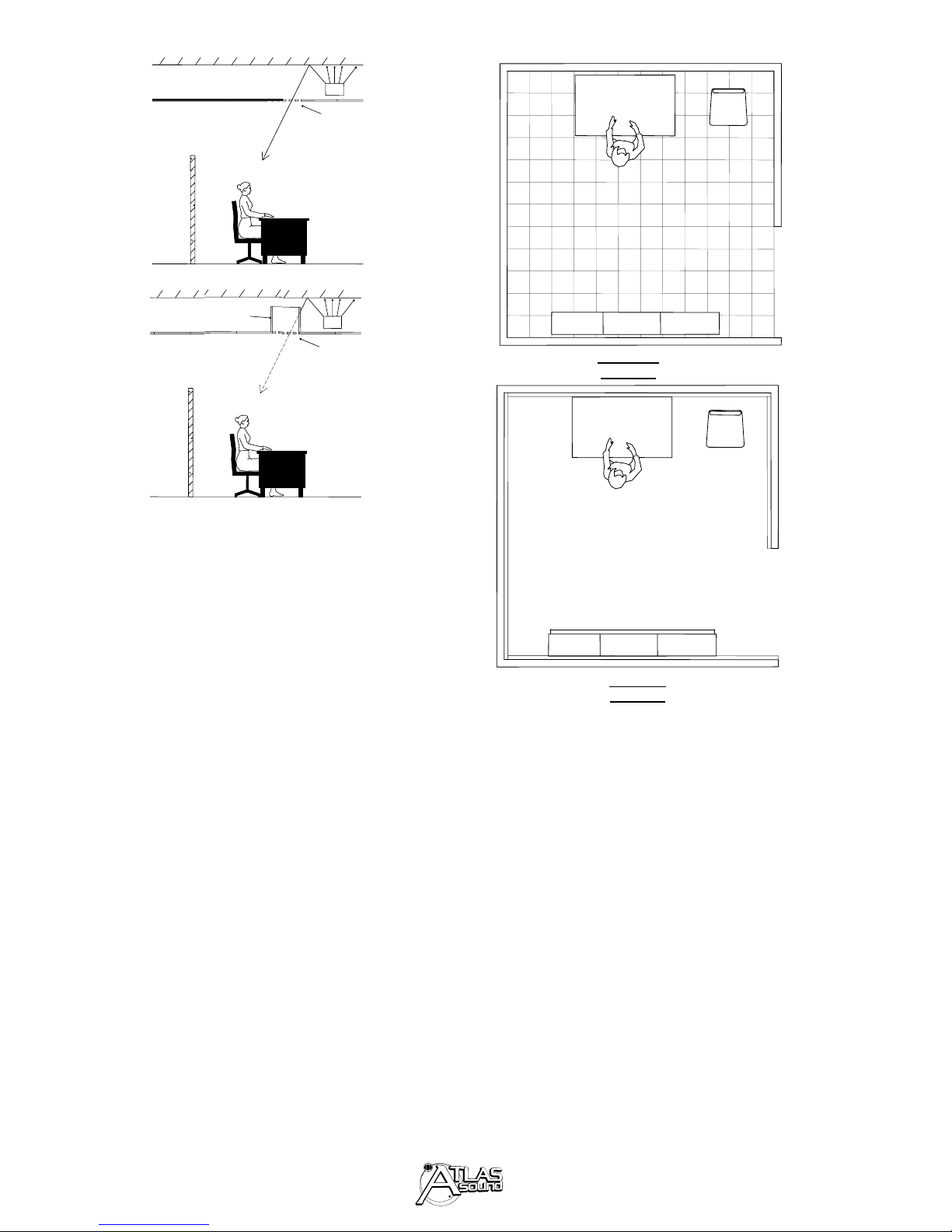
Lighting Fixtures
Typical ceiling-mounted fluorescent lighting
fixtures have flat plastic lenses flush with the
ceiling. These fixtures reflect speech frequencies between workstations, “short-circuiting”
the acoustic privacy provided by the workstation partition screens. To avoid this problem,
do the following:
* Best — use indirect lighting in the work
station and eliminate fluorescent ceiling
fixtures.
* Good — use parabolic lens or open grid
lighting fixtures and avoid placement over
workstation partition screens.
* Marginal — use flat lens fluorescent fix-
tures but avoid placement over screens.
When a client is unwilling to spend the
money to replace flat lens lighting fixtures
with parabolic lens types, ensure that the
flat lens fixtures are not located over
workstation partition screens. Often, fluorescent fixtures utilize flexible electrical
conduit and can be moved to a new position without re-wiring. Figure 7 shows
good and bad placement of fluorescent fixtures.
Masking Loudspeakers
and the Ceiling
Sound masking loudspeakers are usually
installed above the ceiling. Thus, the
ceiling in an open-plan office must be
capable of passing masking sound without excessive attenuation.
Special ceiling tiles
Foil-backed ceiling tile may be specified to
diffuse the masking sound above the ceiling.
High transmission loss tile may also be
specified for sound masking. However,
these special tile types are not really necessary in a correctly-designed masking system. In fact, they can cause problems.
There are always small sound leaks in the
ceiling. With normal ceiling tile the masking sound coming through these leaks is
low in level and generally not a problem.
If, however, the masking sound level is
increased to force sufficient masking sound
through high transmission loss ceiling tiles,
then the masking sound eminating from the
leaks may increase to the point that it
becomes audible and distracting.
High transmission loss ceiling tiles can
increase speech privacy between standard
walled offices when masking is not provided.
Sound leaks
Although small ceiling leaks may not be a
problem, it’s best to avoid all leaks to the
extent possible. The first place to look for
sound leaks is the return air system.
In a typical open-plan space, room air
returns to the building mechanical system
through a ceiling plenum (the space
between the ceiling and the deck). The air
gets into the plenum through air return
grilles installed directly in the ceiling.
These grilles provide an open door for
masking sound to leak into the office space
below. Beneath these grilles, the masking
sound will be louder and more high-pitched
Light Fixture
FIG. 7 - Speech frequencies reflect off the flat
lenses of ceiling fluorescent fixtures. If the fluorescent fixtures are mounted over workstation
partition screens, this reflected sound can
reduce speech privacy.
Page 14
Bad
Good
Light Fixture Light Fixture
Page 15
and the masking sound coverage will be
uneven. These are very undesirable results.
Lighting fixtures with open grid diffusers
can cause similar problems.
Other Causes of
Unwanted Reflections
Ceilings aren’t the only source of reflected
sound problems in an open-plan office. As
illustrated in Figure 9, hard floors and walls
and even office furniture can contribute to
unwanted reflections.
Boots
To prevent leaks in the ceilings of new
buildings, install a length of fiberglass duct
(called a boot) at each return air register.
Figure 8 shows a return air register before
and after the installation of a boot. In existing spaces, the sound masking contractor
can fabricate boots. Use four 2’ x 4’ ceiling
tiles (matching the tiles in the ceiling) set
on end to form a 4’ high vertical boot that is
2’ x 2’ in section. Attach the tiles together
with duct tape. Maintain the full opening
area (typically four square feet), especially if
the ceiling to deck distance is short (do not
“pinch” air between the boot and the deck).
Open-plan offices must be carpeted. Thick
padded carpets provide more voice frequency absorption than thin, direct glue-down
carpets. Carpeting also reduces the irritation of footfall noises.
Choose absorptive office furniture including
cloth-covered and thickly padded chairs
(avoid leather chairs). If possible, select
office furniture with absorption on its sur-
Plenum Air
FIG. 8 - Install boots above open return air ducts
in ceiling plenums.
FIG. 9 - Use absorptive office furnishings and
thick, padded carpet to reduce unwanted
reflected sound.
Page 15
Return
Air Ret urn
Grille
Wood / gyp.
Walls or Hard
Screens
Wood / Metal
Chairs
Tile Floor
Return
Air Return
Boot
Boot
Air Ret urn
Grille
Plenum Air
Air Return
Wood Shelves
Hard Space
Plan View
Upholstered
Chairs
Absorptive
Wall Pa nels
or Screens
Carpet Floor
(padded)
Wood Shelves with Absorptive Panels
Soft Space
Plan View
Page 16

faces such as shelf covers and drawer faces.
Of course, workstation partition screens
must be highly absorptive.
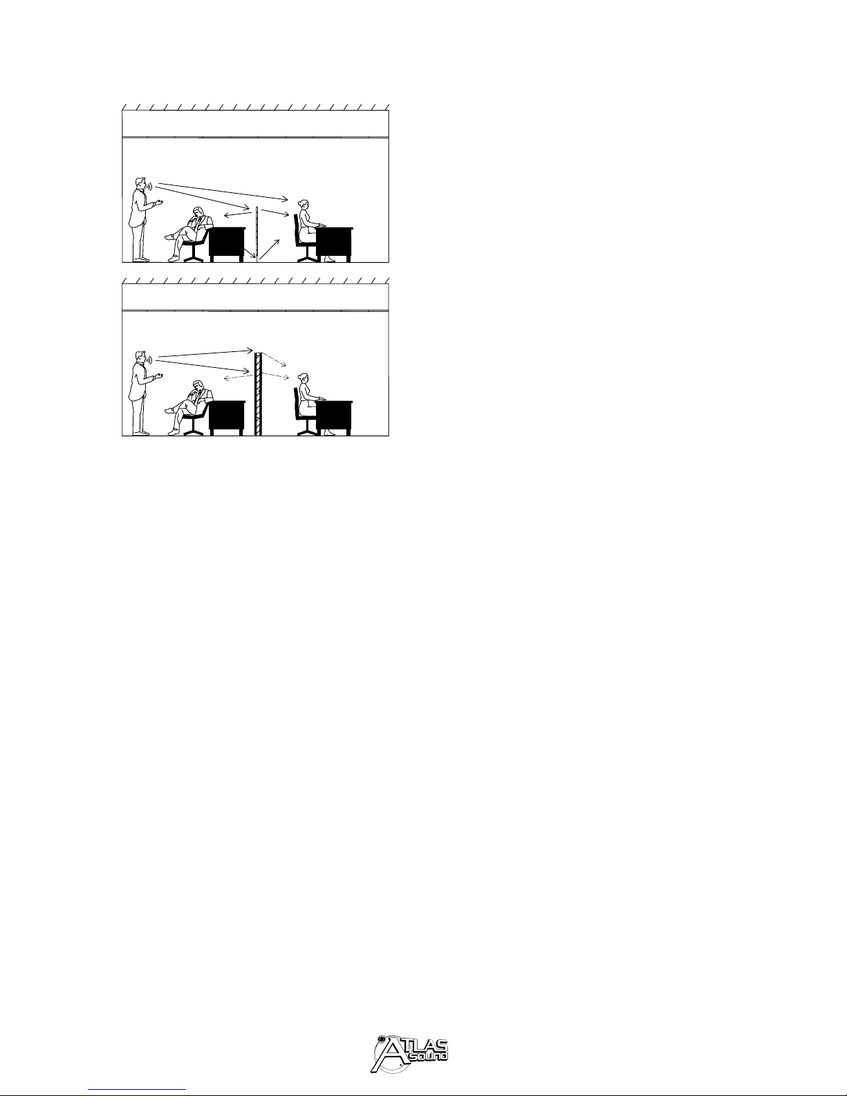
Hard walls, doors and windows can seriously degrade speech privacy in both open-plan
spaces and in standard offices. Any hard,
flat vertical surface such as a fixed wall,
movable wall (curtain wall), window, or
door can bypass the workstation screen barrier and reflect speech sound into an adjacent workstation (see the previous discussion of ceiling lighting fixtures). Figure 10
shows wall reflections and some possible
solutions.
Sometimes, the best way to solve reflection
problems is to change the room layout so
that sound (speech) coming from one workstation can’t reflect into openings in another
workstation. When room layout changes
aren’t possible, add absorption to reduce the
level of the reflected sound.
For walls, add the kind of acoustical wall
panels that have an absorptive core material
(usually rigid fiberglass board), a cloth covering (special fabrics for interior finish use),
and a mounting system. Standard acoustical wall panels come in 2´x 2´, 2´x 4´, and
4´x 4´ sizes and in 1 inch and 2 inch thicknesses. Options include custom artwork or
logo design, impact-resistant core material,
and alternate mounting methods.
The outside wall in a glass building (the
“curtain wall”), reflects sound between
nearby open-plan workstations, reducing
speech privacy. Acoustical wall panels
could attenuate this reflected sound but
would also block incoming light. One way
to solve this problem is to install acoustic
wall panels at 90oto the curtain wall as
shown in Figure 10.
Hard Wall
FIG. 10 - Walls, doors, windows and curtain walls can reflect sound into adjacent workstations.
Page 16
Sound
Absorbing
Baffles
Glass Window
Acoustical
Wall Panel
Glass Window Hard Wall
Extend
Screen to
wall
PLAN VIEW
Page 17

Ambient Noise
To the extent possible, keep building and
office equipment noises below the level of
the masking system. The heating, ventilating, and air conditioning (HVAC) system
makes a sound similar to an electronic
masking sound. However, the level and
spectrum will be different from workstation
to workstation and, in many buildings, the
system cycles on and off.
Acousticians use one of two descriptors to
rate HVAC system noise: Noise Criteria (NC)
or Room Criteria (RC). Since the masking
sound will be approximately RC 40, the
HVAC sound should be no higher than RC
35 or NC 35. Evaluate the office equipment
and building noise in an existing space by
measuring the octave band sound levels
with the HVAC system operating and office
equipment being used. Ensure that each
octave band sound level is 5 dB lower than
the corresponding masking sound octave
band level (See “Masking Spectrum” in Part
6) for the 250-Hz through the 4000-Hz
octave bands. Then add electronic masking
sound to raise background sound levels
high enough to mask voices, but not so
high that people subconsciously raise their
voices.
It’s okay to put a general-purpose conference area in an open-plan office environment. Highly private conference rooms,
however, must be traditional separate
spaces with high STC wall partitions that
extend from the floor to the deck above the
ceiling, sealed heavy doors and no sound
leaks. These conference rooms may still
benefit from reduced levels of masking
sound. For teleconferencing, use very
absorptive interior finishes, very high STC
walls, and no sound masking.
Page 17
Page 18

The electronic sound masking system creates
a “blanket” of background noise carefully
controlled in level, spectrum, and coverage.
Masking sound should not call attention to
itself in any way. It should merely seem to be
part of the general building noise. In fact, if
people are unaware that a masking system is
in operation, they usually believe they are
hearing the ventilation system.
Concept - Don’t Tell the Employees?
One of the early rules of sound masking
installations was “Don’t tell tell the employees that we just installed sound masking”!
Many believed the employees would complain about headaches or other maladies, or
that the masking system was some type of
corporate manipulation. Of course, these
concerns were unfounded. Masking simply
reduces the speech-to-noise ratio and masking sound is no more harmful than any
other low-level mid-frequency sound.
Today, partly because of the popularity of
personal masking units, this early rule no
longer applies. In fact, it is difficult if not
impossible to “sneak” a masking system into
an existing office space. It is better to tell
employees about the masking system and
sell them on its benefits.
Self-Contained Masking Units
Large sound-masking systems may cover
entire floors or even entire office buildings.
Small systems may cover only one office or
workstation. For these small systems, with
only a few loudspeakers, consider self-con-
tained masking units. These self-contained
devices have a built-in masking sound generator, simple equalizer, small amplifier,
and loudspeaker. Generally, self-contained
units use local (workstation) AC power. In
some cases, they can utilize a circulated DC
power supply.
Single-Channel vs Multi-Channel Masking
For budget reasons, masking systems commonly use a single generator, equalizer, and
power amplifier. However, a two-channel,
or even a multi-channel masking system
has a distinct performance advantage.
In a single-channel system, all masking
loudspeakers have the same coherent
signal. As employees walk out of the coverage of one loudspeaker into the next, they
hear phase cancellations between the two
loudspeakers. This “phase shift” sound
draws unwanted attention to the masking
system (ventilation sounds would not produce this effect). Two-channel systems
minimize this problem by connecting adjacent loudspeakers to separate masking generators. Multi-channel systems reduce this
problem to negligible levels.
Basic Electronics
For larger systems, with many masking
loudspeakers, economics dictate a central
rack of equipment containing the masking
sound generators, equalizers, and amplifiers. To enhance security, terminate all
cables inside the rack and close and lock
the rack doors to prevent tampering with
Part 3
The Basic Electronic Sound Masking System
Page 18
Page 19

the equipment. Ensure the rack has
adequate ventilation for uninteruppted
usage 24 hours a day, 365 days a year.
For an existing space, include the cost of an
electrical subcontractor to provide dedicated AC circuits hardwired into the rack.
Consider an uninterruptible power supply
(UPS) to prevent system shutdown during
brief power outages or brownouts.
Sound Masking
and Background Music or Paging
Background music and paging systems
normally use loudspeakers installed in holes
in the ceiling, facing downwards to provide
intelligible, clear sound to the listeners.
Sound masking systems normally use loudspeakers installed above the ceiling tiles,
facing upwards or sideways to randomize
the distribution of the masking sound.
Following these suggestions will make the
most of a combined system. A combined
masking and paging system usually involves
compromise in performance to one system
or the other. However, it is not impossible.
Background music and paging take place at
a higher level than masking. Thus, in a
combined system, choose a higher power
amplifier and loudspeakers and tap the
loudspeakers at a higher level. Always use
separate equalizers for the masking sound
and the background music and/or paging.
Do not allow the masking sound to be
ducked or attenuated during a page. Never
combine masking with a life-safety system.
Basic System Electronics
A basic masking system includes a masking
sound generator, an equalizer, a power
amplifier and one or more loudspeakers.
Figure 11 is the wiring diagram for a basic
masking system. Electronically, basic sound
masking systems are among the simplest
types of sound systems.
Masking Sound Generator
The electronic masking generator (noise
generator) is the heart of the masking system. Pink noise (equal energy per octave)
is the most common masking noise. In rare
situations, a white noise generator (equal
energy per hertz) may benefit the system.
Choose a generator that is rack-mounted,
AC powered and produces a stable noise
signal.
An ideal masking noise generator produces
true random noise that never repeats.
Digital noise generators generate a pseudorandom signal that repeats every so often.
Choose either a true random noise generator (analog) or a digital noise generator
Noise
Gen.
Equalizer
Amplifier
Masking
Loud-
speakers
FIG. 11 - Wiring diagram of a basic sound
masking system.
Page 19
Page 20

with a pseudo-random sequence of at least
several seconds. Test equipment noise generators usually repeat too frequently to be
acceptable for sound masking.
Some masking sound generators have
computer controls that gradually reduce
the normal daytime masking sound to a preset nighttime level. This reduction usually
begins just after normal office hours and
slowly takes place over one to two hours.
Then, one to two hours before the office
reopens, the masking sound level gradually
ramps back up to the normal level. The
level change is usually on the order of 6 dB.
However, in some circumstances, masking
sound is more critical during quiet afterhours times.
Equalizer
For sound masking, use a third-octave
equalizer with included high and low pass
filters, interpolating filter interaction
response and overall shaping filters.
Interpolating filters allow a boost or cut at a
frequency between two adjacent thirdoctave frequencies by the relative settings of
the adjacent filter controls. Alternately, use
a parametric equalizer. The best parametrics have control over the complete audio
range in each filter. Other signal processing
devices such as delays, crossovers, and
notch filters are not normally required for
masking systems.
Amplifier
Use high quality professional or commercial
grade power amplifiers with 70-volt outputs
for sound masking. The ability to run continuously year in and year out is much more
important in a masking amplifier than good
audio performance.
Page 20
Page 21

Very simple masking systems, with only the
bare minimum of components, are fairly
rare. More commonly, a masking system
includes a two-channel generator, signal
monitoring for troubleshooting and sometimes even paging or background music.
Figure 12 is the wiring diagram for a twochannel system with background music,
zone level controls and signal monitoring.
Two (and more) Channel Masking
Two-channel masking systems route
separate masking signals to adjacent loudspeakers. Because the sound from adjacent
loudspeakers is no longer coherent, employees can walk from place to place in the
workspace without hearing the “phasing”
sound typical of single-channel systems.
To create a two-channel masking system,
add a second masking generator, equalizer
and power amplifier to the basic system (or
use a two-channel power amplifier).
Part 4
Multi-Channel Masking, Background Music,
and Paging
FIG. 12 - Wiring diagram of a two-channel sound-masking system with zone level controls,
background music, and an amplified monitor panel.
Page 21
Amplifier
1
Noise
Gen.
Ch. A
Music
Source
Noise
Gen.
Ch. B
Equalizer
Ch. A
Equalizer
Ch. B
4-In
2-Out
Mixer
1
2
3
4
2
3
4
5
6
7
A
B
Amplified
Monitor
Panel
Amplifer
A
B
Zone
Level
Controls
A1
B1
A2
B2
A3
B3
Masking
Loud-
speakers
Page 22

Zone Level Controls
Larger masking systems may cover more
than one workspace in a building. Unless
the workspaces are acoustically very similar, each deserves its own masking sound
level control. Even in a single large room,
it may be useful to provide separate level
controls for open areas, walled offices, conference rooms and corridors.
Discuss level-control zones with the client
early in the masking system design. Use
autoformer-type level controls with 1.5 dB
steps and sufficient power capacity to serve
all of the loudspeakers in the zone. In
multiple-channel systems, use a separate
control for each channel in each zone.
Provide a rack-mounted panel when the
quantity of controls exceeds one or two. To
avoid tampering, locate zone level controls
behind locked doors (or in the equipment
rack).
Some systems use multiple power-amplifier
channels in place of zone level controls.
Although this method adds cost, it may be a
good solution in systems that include background music or paging.
Amplified Monitor Panel
An amplified monitor panel makes troubleshooting easy. Choose one that allows
monitoring at each point in the system
block diagram, after the masking generator(s), after the equalizer and after each
power amplifier. The monitor panel should
include a VU or LED meter and a loudspeaker. Complex systems may need more
than one monitor panel.
Background Music / Paging
It may be easier to sell a masking system to
certain clients if the system includes background music or paging. Intergrating
masking, paging, and background music
using the same speakers and amplifiers can
be full of compromises for one or all of the
intended uses if not designed properly.
When installing any background music system to avoid copyright infringment, use a
licensed music service to provide the music.
Always use a separate equalizer for the music
so that it sounds natural after penetrating
the acoustical ceiling.
Paging requires a higher sound level than
either masking or background music.
When paging is combined with a masking
loudspeaker system, the paging sound must
be loud enough to penetrate the ceiling tile.
For these reasons, a combination masking
and paging system requires higher-power
amplifiers and loudspeakers. This also suggests that it may be difficult to add paging to
an existing masking system. Remember to
never mute or duck the masking sound in a
combined system.
Page 22
Page 23

Paging Sound Level
To calculate the paging sound level of a
masking loudspeaker at the listener, first
gather the following information:
*
S = loudspeaker sensitivity
(from the manufacturer’s data sheet)
This must be given as dB SPL with 1 watt
input at 1 meter distance
*
P = power delivered to the loudspeaker in
watts (from the system designer)
Usually equal to the power tap on the
loudspeaker transformer
*
D = distance, in meters, from loudspeaker
to listener, including the reflected path.
To convert feet to meters, divide feet by 3.28
*
15dB = SPL level lost as the sound passes
through the ceiling tile.
Substitute the actual loss if it is different
from this typical value for ceiling tile.
After obtaining the data, calculate L, the
paging level at the listener, in dB SPL, with
the following formula:
L = S + 10log10P - 20log10D -15dB
Consider a typical masking system with a
loudspeaker rated at 95 dB sensitivity
(1w/1m), tapped at 2 watts, and aimed at
the deck above the ceiling. The reflected
path length is approximately 14 feet to a
typical listener and the sound must pass
through a mineral-fiber ceiling tile. What is
the expected paging level at the listener’s
position?
Insert these values into the formula to
obtain:
L = 95 +10log10(2) - 20log10(14/3.28) - 15
or L = 95 + 3.0 - 12.6 - 15 = 70.4 dB SPL
In a quiet office, paging levels must be 5 to
6 dB louder than this (about 76dB SPL).
This extra 6dB means quadrupling the
transformer wattage tap to 8 watts.
Chances are, that means a more expensive
transformer and a higher power amplifier.
Paging Equalizers
Use a separate paging equalizer to compensate for the uneven transmission loss (with
frequency) of the ceiling tile. It may be possible for one equalizer to handle both music
and paging, but the masking equalizer must
be separate. Multi-channel masking
complicates a system that includes paging
or background music. Study the block
diagram in such a system to ensure the paging or background music distribution
doesn’t compromise the multi-channel
masking.
Page 23
Page 24

Masking Loudspeakers
Masking loudspeakers are special assemblies designed for installation in ceiling
plenums. A typical assembly consists of a 4
or 8-inch cone speaker, a 70.7-volt speaker
line transformer, a metal enclosure with
baffle, and a hanging/mounting hardware
kit. Since masking does not pose difficult
performance requirements, most masking
loudspeakers are general purpose types
with 10 to 20-watt power ratings.
Manufacturers, such as Atlas-Soundolier,
commonly offer several models of masking
loudspeaker to meet different system
requirements.
Upwards Loudspeaker Orientation
Masking loudspeakers usually face
upwards, towards the deck. In new construction, a system of light-gauge chain suspends each masking loudspeaker. In existing construction, where the plenum is cluttered, choose a masking loudspeaker
designed to be installed on top of the ceiling
tile grid.
A typical office has a 9-foot height to the ceiling tile, a plenum extending about 4 feet
above the ceiling tile and a hard deck at the
top of the plenum. In this kind of construction, mount the masking loudspeakers low in
the plenum space with the bottom of each
loudspeaker about 6 to 8 inches above the
ceiling tile. Point the loudspeakers upward at
the hard deck as shown in Figure 13.
FIG. 13 - Typical masking loudspeaker suspended
in a ceiling plenum with a hard deck.
Space the loudspeakers about 12 to 14 feet
apart horizontally. The sound will reflect off
the deck down through the ceiling tile and
into the space below. This ensures an even
coverage of masking sound because the
sound mixes fairly well in the plenum.
Part 5
Masking Loudspeakers
and Self-Contained Masking Units
Page 24
Hard
Deck
Masking Speaker
Office Below
Suspended Ceiling
Page 25

Downwards Loudspeaker Orientation
Roof decks (above the ceiling on the top
floor of a building) usually have sprayed-on
thermal insulation that is also an efficient
acoustical absorber. In this situation, mount
the masking loudspeakers high in the
plenum and point them downward as
shown in Figure 14.
The effective distance from loudspeaker to
listener is shorter with downward-pointing
loudspeakers because the sound does not
reflect off the deck. This reduces the loudspeaker’s horizontal coverage (compare
Figure 13 and Figure 14). Also, an absorptive deck does not diffuse the sound as well
as a hard deck. Thus, to ensure even coverage in this situation, place the loudspeakers
no more than 8 feet apart horizontally.
Horizontal (Sideways) Loudspeaker
Orientation
Some masking loudspeakers can be suspended sideways so that they radiate sound
horizontally. In general, horizontal orientation has no advantage over upward orientation and upward orientation will usually
provide more even coverage.
However, horizontal orientation can be an
advantage near an unavoidable leak in the
ceiling. Orient the masking loudspeakers
horizontally to radiate sound away from the
leak during the system commissioning
process.
In-Ceiling Placement
Occasionally, the plenum may be crowded
with obstructions which would prevent even
coverage of the masking sound.
Occasionally, the space between the ceiling
tiles and the deck may be very short. In
these cases, install standard, down-firing
ceiling speakers, like those used for background music or paging. To prevent “hot
spots,” do the following:
* Space the loudspeakers very close together
and overlap their coverage.
* Use 4-inch ceiling speakers which have
wider dispersion than 8-inch models.
* Use at least two masking channels so the
sound is not mixed in the
plenum.
* Use back box enclosures to keep rear-radi-
ated sound from reflecting through ceiling
leaks and causing hot spots.
Valuable Masking Loudspeaker
Features
Some masking loudspeakers include a
rotary switch, mounted on the outside of the
assembly, to select the internal 70-volt
transformer’s wattage taps. This makes it
possible to adjust the power to each loudspeaker without disassembling the unit.
During system testing, select a wattage tap
that produces masking sound approximately
10 dB above the background sound in the
voice-range third-octave bands (typically
the 2-watt tap). As stated earlier, combined
paging and masking systems usually require
a higher wattage tap.
Choose masking loudspeakers that come
with electrical boxes mounted to the sides
of their enclosures or with conduit-compatible access plates. Whether the installation
uses conduit or plenum-rated cable without
Page 25
FIG. 14 - If the underside of the deck is absorptive because of sprayed-on thermal insulation
(top floor of many buildings), mount the masking loudspeakers as high as possible and point
them downwards. This configuration requires
more loudspeakers to maintain even coverage.
Hard Deck
with
Insulation
Masking Speaker
Office Below
Suspended Ceiling
Page 26

conduit, make the loudspeaker connections
inside the electrical box or inside the enclosure to avoid violating local building safety
codes. Always comply with all state and
local codes, as well as the National
Electrical Code, for any masking loudspeaker installation.
Self-Contained Masking Units
Self-contained masking units consist of a
masking sound generator, equalizer, amplifier, and loudspeaker in one compact unit,
basically a complete sound masking system
in a box. Some self-contained masking
units operate from standard AC power,
while others operate from a shared DC
power supply. In general, if the application
requires only one or two units, the AC
power version is easier to install. If the
application requires several units, it is
cheaper to provide one DC power supply
that feeds several units.
Install self-contained masking units in the
ceiling plenum just like any other masking
loudspeaker, or place them in an inconspicuous place in an office to accomplish “spot”
masking as shown in Figure 15.
Sometimes, self-contained masking units
can help sell a prospective client on the
benefits of a permanent masking system.
Install one or more self-contained masking
units in a small area of their space on a trial
basis.
Self-contained masking units can be mounted either above or below the ceiling. For
this reason, they must have level controls
and filters to adjust the masking sound for
the chosen location.
FIG. 15 - A self-contained masking unit used as
a “spot” masker in an office.
Page 26
Page 27

“Commissioning” the masking system
takes place in two steps:
1.
Confirm the proper installation and
function of all system components.
2.
Adjust the system level, spectrum and
coverage to the design specification.
Good coverage simply means every listener
hears masking sound at the desired level and
spectrum given in the initial specification.
Level
Proper masking sound level is very important. If the masking level is too low, it won’t
do its job of increasing speech privacy. If
the masking level is too high, people in the
space will subconsciously raise their voices,
negating any improvements in speech
privacy.
Masking sound level for the listener should
be between 45 and 50 dB(A) (A-weighted
SPL decibels). Implementing the thirdoctave band levels given in the Part 6
section entitled “Ideal Masking Spectrum”
will result in a masking level of 47 dB(A).
Connecting Spaces
Sometimes one part of a building has masking sound while a connecting space does not.
Taper the masking sound level between these
areas. An abrupt level difference would
make the masking sound much more noticeable to people walking between the two
spaces. To achieve the tapering, add a few
masking loudspeakers between the two
spaces tapped at a lower wattage setting.
Setting the Level During System
Adjustment
During system adjustment, set the masking
level above background sounds such as those
created by the building heating, ventilating,
and air-conditioning (HVAC) system. This
makes it possible to adjust the masking spectrum without influence from these background
noises. Ideally, the masking level should be
10 dB above background noises during this
phase. However, it may not be possible to
achieve this goal for the lower octave bands
since HVAC sounds may be quite loud in those
lower bands. After adjusting the spectrum,
reduce the masking level to its proper speech
privacy level of approximately 47 dB(A).
Gradually Adjust to Final Level
It’s a good idea to let people in the masking
environment become accustomed to a new
masking system over a period of several
weeks. Start by setting the masking level 6 dB
lower than the desired level. Operate the system at this reduced level for one week, then
increase the level 1.5 dB during off-hours.
Raise the level another 1.5 dB at the end of
each week until the system reaches the desired
masking level. Use precision attenuators, with
1.5 dB steps, or use a loudspeaker zone level
control panel if the system has one. If the system is easy to adjust, the client can make the
adjustment after the close of business each
week. To gradually change the level automatically, use the kind of microprocessor-controlled masking sound generators described
previously. If a client has a severe speech privacy problem, accelerate the level step-up
pro-
gram or dispense with it altogether.
Part 6
Commissioning the Masking System
Page 27
Page 28

Masking Spectrum
Figure 16 shows a typical masking spectrum
compared to typical “quiet” building sound,
pink noise, and white noise.
FIG. 16 - Octave-band sound pressure levels of
typical masking sound (solid line curve), typical
“quiet” building background sound (dotted line
curve), pink noise (horizontal straight line
plot), and white noise (upward-sloping straight
line plot). The white noise and pink noise
spectra are shown normalized to match the
masking level at 500 Hz.
Ideal Masking Sound Spectrum
To achieve the best speech privacy at a
listener’s position, the masking sound
spectrum should be similar to the spectrum
of average voices. Because the spectrum of
average voices depends on the acoustical
environment, the ideal masking spectrum
also changes with the acoustical environment. Following are three masking spectra chosen to illustrate this ideal in different
acoustical environments. All three curves
are given to the nearest tenth of a dB only to
show the trend of the curve. In actual practice, it is challenging to stay within desired
dB tolerances at all locations.
Masking Spectrum 1
Masking Spectrum 1, given in the table
below, is appropriate for a walled space or
ideal open-plan space (5-foot minimum
height screens, absorptive ceilings and
furnishings, and proper layout).
Masking Spectrum 1 above is plotted in Figure
17 and is the preferred spectrum for properly
designed interiors because its sound quality is
very neutral and unobtrusive.
Page 28
FIG. 17
SOUND PRESSURE LEVEL re 20 µPa,
dB
60
50
40
30
20
10
125 250
OCTAVE-BAND CENTER FREQUENCIES,
500
Hz
1000
200063
4000
8000
1/3rd-
Octave
Band
50 Hz: 47.0 (+4/-6) dB
63 Hz: 47.0 (+4/-5) dB
80 Hz:
100 Hz:
125 Hz:
160 Hz:
200 Hz:
250 Hz:
315 Hz:
400 Hz:
500 Hz:
630 Hz:
800 Hz:
1000 Hz:
1250 Hz:
1600 Hz:
2000 Hz:
2500 Hz:
3150 Hz:
4000 Hz:
5000 Hz:
6300 Hz:
8000 Hz:
10,000 Hz: 12.0 (+4/-6) dB
SOUND PRESSURE LEVEL re 20 µPa,
dB
50
40
30
20
dB SPL
47.0 (± 4) dB
47.0 (± 3) dB
47.0 (± 3) dB
46.0 (± 3) dB
45.0 (± 2) dB
44.0 (± 2) dB
42.7 (± 2) dB
41.3 (± 2) dB
40.0 (± 2) dB
38.3 (± 2) dB
36.7 (± 2) dB
35.0 (± 2) dB
33.3 (± 2) dB
31.7 (± 2) dB
30.0 (± 2) dB
28.3 (± 2) dB
26.7 (± 2) dB
25.0 (± 2) dB
22.3 (± 2) dB
19.7 (± 3) dB
17.0 (± 4) dB
10
0
63 125 250 500
THIRD-OCTAVE BAND CENTER
FREQUENCIES, Hz
1000 2000 4000 2000
Page 29

Masking Spectrum 2
Masking Spectrum 2, given in the table
below, and charted in Figure 18, is appropriate for good open-plan spaces (screens 4 - 5
feet high, some reflective surfaces, and
moderate furniture absorption). Compared
to Masking Spectrum 1, Masking Spectrum
2 increases the sound level slightly (2 dB) at
2000 Hz, the band that contributes most to
intelligibility. This spectrum still results in
fairly neutral masking sound quality.
The dotted-line curves show the tolerance
of the spectrum which is appropriate for
good open plan spaces.
Masking Spectrum 3
Masking Spectrum 3, given in the table below,
and charted in Figure 19, is appropriate for
non-ideal open-plan spaces (no screens or
screens under 4 feet high, reflective surfaces,
and moderate furniture absorption).
Compared to Masking Spectrum 1, Masking
Spectrum 3 increases the sound level by 4 dB
at 2000 Hz. This spectrum will result in less
neutral masking sound quality than either
Masking Spectrum 1 or 2.
The dotted-line
curves show the tolerance of this spectrum
which is appropriate for non-ideal openplan spaces.
Page 29
FIG. 18 FIG. 19
1/3rd-
Octave
Band
50 Hz: 45.0 (+4/-6) dB
63 Hz: 45.0 (+4/-5) dB
80 Hz:
100 Hz:
125 Hz:
160 Hz:
200 Hz:
250 Hz:
315 Hz:
400 Hz:
500 Hz:
630 Hz:
800 Hz:
1000 Hz:
1250 Hz:
1600 Hz:
2000 Hz:
2500 Hz:
3150 Hz:
4000 Hz:
5000 Hz:
6300 Hz:
8000 Hz:
10,000 Hz: 12.0 (+4/-6) dB
dB SPL
45.0 (± 4) dB
45.0 (± 3) dB
45.0 (± 3) dB
44.3 (± 3) dB
43.7 (± 2) dB
43.0 (± 2) dB
42.0 (± 2) dB
41.0 (± 2) dB
40.0 (± 2) dB
38.7 (± 2) dB
37.3 (± 2) dB
36.0 (± 2) dB
34.7 (± 2) dB
33.3 (± 2) dB
32.0 (± 2) dB
30.3 (± 2) dB
28.7 (± 2) dB
27.0 (± 2) dB
23.7 (± 2) dB
20.3 (± 3) dB
17.0 (± 4) dB
1/3rd-
Octave
Band
50 Hz: 43.0 (+4/-6) dB
63 Hz: 43.0 (+4/-5) dB
80 Hz:
100 Hz:
125 Hz:
160 Hz:
200 Hz:
250 Hz:
315 Hz:
400 Hz:
500 Hz:
630 Hz:
800 Hz:
1000 Hz:
1250 Hz:
1600 Hz:
2000 Hz:
2500 Hz:
3150 Hz:
4000 Hz:
5000 Hz:
6300 Hz:
8000 Hz:
10,000 Hz: 12.0 (+4/-6) dB
dB SPL
43.0 (± 4) dB
43.0 (± 3) dB
43.0 (± 3) dB
42.7 (± 3) dB
42.3 (± 2) dB
42.0 (± 2) dB
41.3 (± 2) dB
40.7 (± 2) dB
40.0 (± 2) dB
39.0 (± 2) dB
38.0 (± 2) dB
37.0 (± 2) dB
36.0 (± 2) dB
35.0 (± 2) dB
34.0 (± 2) dB
32.0 (± 2) dB
30.0 (± 2) dB
28.0 (± 2) dB
25.0 (± 2) dB
21.0 (± 3) dB
17.0 (± 4) dB
SOUND PRESSURE LEVEL re 20 µPa,
dB
50
40
30
20
10
0
THIRD-OCTAVE-BAND CENTER
FREQUENCIES, Hz
1000 2000 4000 8000250 50063 125
SOUND PRESSURE LEVEL re 20 µPa,
dB
50
40
30
20
10
0
1000 2000 4000 8000250 50063 125
THIRD-OCTAVE-BAND CENTER
FREQUENCIES, Hz
Page 30

Comparison of
All Three Masking Spectra
Equalizing the System:
The Equalization Process
After selecting one of the three masking
spectra, equalize the system as follows: Use
a 1/3-octave spectrum analyzer, measuring
microphone, sound level meter (SLM) and
oscilloscope. It may be possible to use the
SLM as the measuring microphone. See the
section entitled “Test Equipment” for a
more thorough discussion of test equipment
requirements.
Locate the microphone in a typical listening
position, as described below, and locate the
spectrum analyzer at the equipment rack.
*
Set all amplifier input controls fully counter-clockwise so there is no masking sound
through the loudspeakers.
*
Set the system equalizer controls to the flat
position.
*
Set any equalizer gain controls to achieve
unity gain on all channels.
*
Place the measuring microphone in a
typical listening position at ear level.
*
Increase the gain for the amplifier feeding
this listening position until the masking
sound level is 50 dB SPL in the 500-Hz
third-octave band as seen on the spectrum
analyzer.
*
Ensure the amplifier is not clipping. Connect the oscilloscope to the amplifier output and look for squared-off wave tops
which indicate clipping.
*
Increase the amplifier gain 10 dB so the
sound level at 500 Hz is 60 dB SPL.
*
Again, ensure the amplifier is not clipping.
*
Now, adjust the equalizer to reach the
desired spectrum between 200 Hz and 5000
Hz.
*
Try moving the measuring microphone if
it
seems necessary to adjust any individual
equalizer control more than 3 dB above the
unity gain position. This will avoid overstressing the amplifier and loudspeakers.
*
If low frequencies cannot be adjusted to
this elevated level, readjust these bands
later when the masking sound level has
been reduced to the final level.
*
Reset the amplifier gain fully counterclockwise (no masking sound).
*
Repeat the previous steps for each channel
in the system, ending with all amplifier
controls fully counter-clockwise.
*
Finally increase the amplifier gain controls
equally on all channels until the sound
level meter reads 47 dB(A) at all listening
positions.
*
If necessary, readjust the low-frequency
bands.
*
Fine-tune the equalizer so that the building HVAC noise and masking sound
together achieve the desired spectrum.
*
Check the coverage at additional listening
positions as described next.
Page 30
FIG. 20 - Comparison of Masking Spectra:
Sound Masking Spectrum 1
(preferred)
Sound Masking Spectrum 2
Sound Masking Spectrum 3
SOUND PRESSURE LEVEL re 20 µPa,
dB
50
40
30
20
10
0
250 50063 125
THIRD-OCTAVE-BAND CENTER
FREQUENCY, Hz
1000 2000 4000 8000
Page 31

Coverage
With the system in normal operation, walk
the space, using your ears and a meter to
assess the masking level and spectrum
throughout the entire space. If necessary,
fix problems and readjust the system as
follows:
* While walking the space, listen and
observe the meter to find any “hot spots.”
* Determine the cause of any hot spots
(open return air grill, etc.).
* Fix the problems before re-adjusting the
masking system (return air boot).
* Remember to check levels in any walled
offices served by the masking system.
* If the level is too high in these walled
offices, which is typical, adjust the transformer taps for the appropriate masking
loudspeakers.
*
If the system has zone controls, adjust them
to achieve the same level in all zones.
* Re-check all areas, adjusting transformer
wattage taps as required.
* If uneven coverage remains, re-orient,
move, or turn off loudspeakers as required.
Ensuring good coverage is a tedious
process, but it is necessary to achieve the
desired masking performance throughout
the space. The final masking sound level
should not deviate more than 2 dB(A) from
the desired spectrum throughout the entire
space, except where it is deliberately
tapered down like entry ways.
Test Equipment
Masking system installers need proper test
equipment to set masking levels and spectra. Start with a sound level meter (SLM)
meeting American National Standards
Institute (ANSI) Class 1 standards for precision accuracy. Ideally, this SLM should
have A-weighting, C-weighting, linear (flat)
response, octave filters, and third-octave filters. An ANSI Class 1 real time analyzer
will make the job easier because it displays
all third-octave bands at one time.
Changes in temperature, humidity, and
barometric pressure can cause changes in
the accuracy of the sound level meter or
analyzer. For this reason, they must have
dedicated acoustic calibrators. The acoustic
calibrator is a precision sound pressure
source that couples to the measurement
microphone of the unit. Use the calibrator
before every measurement session to
ensure that the instrument is reading true
sound levels. Return the instrument and the
calibrator to the manufacturer once a year
to be re-calibrated to national standards.
Page 31
Using an Octave-Band Equalizer for
Troubleshooting
Although it cannot be used to commission the system, a hand-held, octave-band analyzer
is a convenient way to troubleshoot or survey the masking system. Because each band in
an octave-band analyzer receives the energy from three 1/3-octave bands, proper levels are
approximately 5 dB higher than those given in the 1/3-octave tables above. The following
three tables give octave-band levels for the three masking spectrums discussed earlier.
Masking Spectrum 1 Masking Spectrum 2 Masking Spectrum 3
Octave
Band
63 Hz: 52 dB 63 Hz: 50 dB 63 Hz: 48 dB
125 Hz: 52 dB 125 Hz: 50 dB 125 Hz: 48 dB
250 Hz: 49 dB 250 Hz: 48 dB 250 Hz: 47 dB
500 Hz: 45 dB 500 Hz: 45 dB 500 Hz: 45 dB
1000 Hz: 40 dB 1000 Hz: 41 dB 1000 Hz: 42 dB
2000 Hz: 35 dB 2000 Hz: 37 dB 2000 Hz: 39 dB
4000 Hz: 30 dB 4000 Hz: 32 dB 4000 Hz: 33 dB
8000 Hz: 22 dB 8000 Hz: 22 dB 8000 Hz: 22 dB
dB SPL Octave
Band
dB SPL Octave
Band
dB SPL
Page 32

As originally discussed, the goal of most masking systems is to increase speech privacy.
A well-planned sound masking system
achieves this goal by reducing speech sound
energy and increasing background sound
(with masking sound). But how can speech
privacy be quantified? This section shows
how to predict articulation and privacy and
it discusses how to use the speech privacy
worksheet given as Appendix B.
Articulation Index and Privacy
Category Definitions
The Articulation Index (AI), rates speech
intelligibility with a two-decimal place fraction between 0.00 (no intelligibility) and
1.00 (perfect intelligibility). Specifically, AI
rates speech intelligibility in relation to
background noise, so this is a very useful
measurement term in the field of sound
masking.
ANSI Standard S3.5 gives three methods for
calculating AI: the 20-band method, the
third-octave band method, and the octave
band method. Of the three, the 20-band
method is the most accurate, but also the
most difficult to implement. The octave
band method is easy to calculate, but is the
least accurate. For the purposes of this
paper however, the octave band method is
accurate enough.
Speech privacy can be considered the
inverse of speech intelligibility. The higher
the intelligibility, the lower the privacy, and
vice versa. Therefore, calculating speech
intelligibility makes it possible to predict
speech privacy. The following table relates
AI to subjective speech intelligibility and
speech privacy:
Subjective Speech Intelligibility
Articulation Index
The terms Excellent, Good, Fair, Poor, and
Bad are standard subjective terms used to
describe speech intelligibility and to rate AI
scores. Similarly, the terms Marginal,
Normal, and Confidential are subjective
terms used to describe speech privacy.
Notice that all the privacy ratings fall under
the Bad intelligibility category.
Marginal Privacy
Marginal is the minimum rating that could
be used to describe speech privacy.
Eavesdropping is very easy in a marginal
speech privacy environment and audible
conversations may distract employees.
Page 32
Part 7
PREDICTING PRIVACY
IN THE MASKING ENVIRONMENT
Subjective Speech
Intelligibility
Articulation Index Subjective Speech Privacy
Excellent 0.75 – 1.00 none
Good 0.60 – 0.74 none
Fair 0.45 – 0.59 none
Poor 0.33 – 0.44 none
Bad 0.20 – 0.32 Marginal (0.20 to 0.30)
Bad 0.05 – 0.19 Normal
Bad 0.00 – 0.04 Confidential
Page 33

Normal Privacy
Normal is usually the best level of speech
privacy achieveable in an open-plan office
space. A masking installation that achieves
normal privacy will reduce distractions from
nearby conversations, footfall noise, and the
sounds of office equipment. However, even
in a normal privacy installation, listeners
will still be able to hear speech, and they
may even be able to eavesdrop, if they listen
carefully and know something about the
subject of the conversation.
Confidential Privacy
Confidential privacy is expected in certain
offices and conference rooms. With
Confidential privacy, listeners may hear
conversations from adjacent rooms, but
these conversations will not be intelligible.
Eavesdropping is not usually possible in
environments with confidential privacy.
Total Privacy
Occasionally, a client may expect total privacy, so that speech from one space is completely inaudible in adjacent spaces. Sound
masking alone will not ensure Total privacy.
Total privacy requires special construction
techniques, materials, and building layouts,
and is therefore beyond the scope of this
paper.
Predicting Speech Privacy
When an acoustical consulting firm designs
a sound masking system, they will tell the
client what speech privacy can be expected.
The acoustical consulting firm is usually
part of a design team working closely with
the architect. As a result, the consultant
will recommend the screens, ceilings, furni-
ture, wall types, and layouts. The acoustical
consultant will also design the sound masking system to meet the client’s needs.
Because the results of a sound masking system are so heavily dependent upon the
acoustics of the space, it is usually better for
the sound masking contractor to let the
acoustical consultant predict the privacy
criteria.
In retrofit situations, the client will often
contact a sound contractor directly for
sound masking. In that case, the contractor
should make a reasonable prediction of the
achievable speech privacy.
The worksheet in Appendix B is an aid to
sound contractors evaluating spaces for
sound masking. By cataloging the layout,
furniture, screens, ceiling, and other items,
the worksheet helps calculate the articulation index, which can be converted to a subjective privacy rating.
Run the worksheet calculations for the
existing condition, then for hypothetical
improvements such as addition of masking
sound, increased screen height, and absorptive ceiling tile. Of course, the accuracy of
the worksheet is directly related to the
detail level and accuracy of the acoustical
assessment. To aid in this assessment, the
worksheet instructions contain information
about evaluating building furnishings and
fixtures.
After the worksheet, several examples show
the typical process of evaluating a space.
Examples are given for open plan and standard walled office spaces.
The following case histories describe real
problems and solutions encountered on
actual projects. These cases illustrate principles given in this paper.
Page 33
Page 34

Masking Improves Speech Privacy
in a Quiet Space
In the open-plan offices of a major oil company, nighttime ambient noise levels were
very low. As a result, employees could carry
on normal-voice line-of-sight conversations
over distances greater than 60 feet and
speech privacy was effectively impossible.
Masking sound was an obvious and successful solution.
Boots Reduce Hot Spots Problem
In one project, the client wanted a masking
system design for an existing space. Even
though the design specified boots over the
air registers, the ceiling contractor did not
install them resulting in hot spots in masking sound coverage.
The client needed to move into the space
immediately, so the masking sound contractor moved and re-aimed and re-tapped the
masking loudspeakers to create acceptable
coverage. However, this did not completely
solve the hot spots problem.
Finally, the masking sound contractor created simple boots by duct-taping four ceiling
tiles together to form a 2-ft square duct, four
feet tall. Each boot was set upright on the
2 ft x 2 ft return air grills. These boots completely eliminated the hot spots under the
return air grills. After re-equalization, the
resulting coverage was much smoother.
Problems Resulting from
Uninstalled Boots
A client had an existing open-plan office
area with speech privacy problems. A site
survey showed that the ceiling had many
(seemingly hundreds!) open return air registers. To work around the problem, the
designer specified that no loudspeaker
could be located closer than 4 feet to a
return air register.
The contractor did a professional installation.
However, final testing revealed a nightmare
of hot spots and uneven coverage. To
achieve even coverage, the contractor turned
many of the loudspeakers completely off.
The contractor grumbled audibly (and with
good reason) about installing so many loudspeakers that were not even used.
To avoid this kind of problem, check the ceiling and HVAC configuration before designing
the masking system. The sound contractor
should install return air boots if there is no
mechanical contractor on the job site.
Leaky Luminaires Cause Hot Spots
On one project, the client had selected
fluorescent light fixtures with open louvered
grids instead of plastic lenses. This type of
fixture scatters reflected sound from below
making it preferrable, for speech privacy, to
a flat lens fixture. However, the metal casing of this particular fixture had many holes
and slots (possibly for venting) that leaked
masking sound into the office below.
To make things worse, the system loud-
Page 34
Part 8
Case Histories
Page 35

speakers were aimed downward because of
the thermal insulation applied to the underside of the deck above. The contractor
could not install boots above the fixtures
because there were a great many fixtures,
the electrical conduits were in the way, and
service personnel would have removed the
boots the first time they serviced a fixture.
To solve the problem, the contractor re-oriented the loudspeakers nearest these fixtures to point horizontally rather than
downward. This reduced the amount of
high frequency energy directed at the fixture itself without having to rely on bouncing sound off the absorptive deck.
Masking Loudspeakers Tapped Too Low
For one low-budget system, the designer
specified a small power amplifier and loudspeakers tapped at 1/2 watt each. The system did the job, but could not achieve a
sound level much above the background
noise making equalization difficult. Also,
the contractor could not tap the loudspeakers downwards to compensate for hot spots,
since 1/2 watt was the lowest tap on the
transformers.
To avoid this problem, specify 4-watt transformers tapped at 2 watts for a normal loudspeaker location. Then, the contractor can
re-adjust loudspeakers in problem areas 3
or 6 dB lower (1-watt or 1/2-watt setting),
or 3 dB higher (4-watt setting). Choose an
amplifier to handle twice the initial load to
allow for expansions to the system and for
tapping loudspeakers to higher wattage
settings.
Complicated System
One very complicated, multi-floor, sound
masking system included background
music, priority zoned paging and supervised
lines. The system also had remote priority
attenuators that increased sound levels
whenever paging occurred in the zone. The
challenge was to design a system that would
maintain constant masking sound level and
constant line supervision.
After a very complicated installation, the
system finally met its design goals.
However, the designers learned a valuable
lesson. For a highly complex design, implement the sound masking portion as a standalone system using loudspeakers above the
ceiling. Then, install the paging and background music portions separately through
standard ceiling loudspeakers. The result
will be better clarity, less equalization, and
much lower power draw. If the masking
system requires supervised lines, try to
avoid speaker-level switching circuits.
Medical Suite Masking Test
Some years ago, sound masking was
uncommon in medical suites. During that
time, one designer proposed sound masking
to a group of doctors who were about to
move to a new professional building. The
doctors, who were unfamiliar with sound
masking, were rightly worried that masking
might drown out the sounds of pulses,
breathing, and other audible symptoms
heard through their stethoscopes.
For this reason, the designer proposed a
trial masking system which was installed
Page 35
Page 36

between two examination rooms and the
area just outside these rooms. The
improvement in speech sound isolation was
immediate and dramatic and the doctors
had no problems using their stethoscopes or
other instruments.
Prior to the test system installation, doctors
and patients could hear every word from the
next examination room. After the installation, the doctors reported that patients were
much more at ease because speech from
the next examination room was unintelligible. In fact, the doctor with the examination
suite with the trial masking system was the
envy of all his colleagues!
Medical Professional Building
Masking
This case history involves the experience of
a patient visiting two doctors. One doctor’s
office had a masking system, the other
didn’t. When visiting the doctor without a
masking system, the patient reported clearly
hearing every word the doctor and another
patient said in an adjoining examination
room even though the doors to both rooms
were closed.
In contrast, when visiting the doctor whose
office had a masking system, the patient
reported hearing but not understanding, the
voices of the doctor and patient talking in
the next room. This masking system had
achieved confidential privacy.
Masking Improves Privacy in a
Pastor’s Office
In a large church, the senior pastor provided marriage counseling and other personal
advisory services in his office. The pastor’s
secretary, whose desk was right outside the
pastor’s office, could hear some of the counseling sessions. When the secretary
informed the pastor about this problem, he
requested an inexpensive solution to the
speech privacy problem. A contractor
installed self-contained masking units in the
pastor’s office, the secretary’s office and the
waiting room. This solved the problem and
shut down a primary source of gossip in the
church!
Masking and Unwanted Reflections in
a Psychiatrist’s Office
Psychiatrist’s offices require extremely confidential privacy. For one particular job, the
doctor wanted to be able to leave her door
open unless it was absolutely necessary to
close it. The door opened to a corridor that
opened to other therapists’ offices in the
same suite. The doctor decided to install
sound masking.
The masking sound designer warned the
doctor that the gypsum board wall in the
corridor would reflect sound into the other
offices, but she and her architect elected not
to treat the wall at first. As a result, the
hard corridor wall almost completely negated the benefits of sound masking, high STC
walls, and special room finishes that had
been installed in the offices.
Finally, with all the other treatments in
place, the problem of sound reflecting
from the corridor wall was so obvious that
the doctor finally decided to add acoustical
treatment to the wall. This solved the
problem.
Page 36
Page 37

Basic masking systems are relatively simple
to design, install and commission but results
are greatly influenced by the acoustics of
the ceilings, screens, furniture and interior
finishes.
When designing a masking
system,remember these three steps:
1.
Reduce the direct speech sound level
(screens, distance)
2.
Reduce the reflected speech sound level
(ceiling, furniture, wall treatments)
3.
Raise the background sound level
(sound masking system)
In an open-plan space, the system designer
and installer must carefully coordinate all
three of these items to achieve acceptable
privacy. In normal offices, adding masking
alone will often make a noticeable difference in speech privacy.
When designing the masking system itself,
remember to optimize these three items:
1.
Level (between 45 dB(A) and 50 dB(A)
2.
Spectrum (chosen masking curve)
3.
Coverage (+ 2 dB throughout space)
Masking sound can lower the speech-tonoise ratio in a space, thereby increasing
speech privacy. Clients in open-plan spaces,
normal office spaces, educational spaces,
medical examination rooms and offices and
many other spaces can benefit from this
increased privacy. By reaching these
clients, systems contractors can benefit
from new business opportunities.
Page 37
Part 8
Conclusion
Page 38

ambient noise - The background noise
in a given environment, usually composed
of many sound sources from many directions, near and far.
articulation class (AC)
- The sum of
the weighted sound attenuation values in
the one-third octave bands between from
200 Hz to 5000 Hz. The rating correlates
with transmitted speech intelligibility
between office spaces. The articulation
class is approximately 10 times the difference in A-weighted levels for sound propagating between talker and listener positions.
Some ceiling tile products carry an articulation class rating. For sound masking in
open-plan offices, design for an articulation
class greater than 200.
articulation index (AI)
- A number
ranging from 0.00 to 1.00 which is a measure of the intelligibility of speech - the higher the number, the greater the intelligibility.
A-weighted sound level - The sound
level in decibels as processed through an Aweighting filter. The A-weighting electronic
filter approximates average human hearing
at low to moderate sound levels. The unit
symbol is dB(A).
background noise - The total noise
from all sources except for a particular
sound that is of interest. (See ambient
noise.)
confidential privacy - Confidential
privacy implies extremely low intelligibility.
An articulation index (AI) of less than 0.05 is
considered confidential privacy.
decibel - A decibel is 10 times the base 10
logarithm of the ratio of two power levels.
Since we measure sound pressure level
more commonly than sound power level, we
extend the definition of the decibel for
sound to be 20 times the base 10 logarithm
of two pressure levels. The decibel is
abbreviated as “dB”.
diffraction - A process whereby a wave-
front changes direction, usually at the edge
of an obstacle or other nonhomogeneity in
the medium, in some way other than reflection or refraction.
direct sound - Sound which reaches a
given location in a direct line from the
source, without reflections.
free field - A sound field (in a homoge-
nous isotropic medium) whose boundaries
exert a negligible influence on sound
waves.
frequency - Of a function that is periodic
in time, the number of times that the quantity repeats itself in 1 second (cycles per
second). Unit: hertz. Unit symbol: Hz.
marginal privacy - Marginal privacy
implies somewhat low intelligibility. An
articulation index (AI) between 0.20 and
0.30 is considered marginal privacy.
masking sound - Masking sound is an
electronically-generated random noise signal (usually pink noise) filtered to achieve a
specific spectrum, amplified to achieve a
specific level, and emitted as sound through
loudspeakers to achieve a specific coverage.
The purpose of masking sound is to raise
ambient sound levels in interior spaces for
increased speech privacy.
Page 38
Appendix A
Definitions
Page 39

noise - (1) Any disagreeable or undesired
sound. (2) A random sound or electronic
signal whose spectrum does not exhibit
clearly discernable frequency components.
noise criterion (NC) curves - A series
of curves of octave band sound spectra used
for rating the noisiness of an occupied
indoor space. The actual noise spectrum is
compared to the noise criteria (NC) curves
to determine the NC level of the space.
noise isolation class (NIC) - A single-
number rating derived from measured values
of noise reduction between two enclosed
spaces that are connected by one or more
paths; this rating is not adjusted or normalized to a standard reverberation time.
noise isolation class prime (NIC’) -
The speech privacy noise isolation class. A
single-number rating similar to the NIC
except that the frequency range under consideration is narrower and the allowable
deviations are less. This descriptor is often
specified in open-plan acoustics.
noise reduction coefficient (NRC) -
A single-number rating of the sound absorption properties of a material like acoustical
ceiling tile or acoustical wall panels; the
arithmetic mean of the sound absorption
coefficients at 250, 500, 1000, and 2000 Hz,
rounded to the nearest multiple of 0.05. For
open-plan sound masking, if a ceiling product does not have an articulation class (AC)
rating, then refer to its noise reduction coefficient. A value of 0.90 or higher is preferred, with 0.70 minimum value for adequate speech privacy.
normal privacy - normal privacy
implies low intelligibility. An articulation
index (AI) between 0.05 and 0.20 is considered normal privacy.
pink noise - An electronically-generated
random noise signal which has equal energy per octave or fractional octave bands.
Pink noise has a flat response on octave or
third-octave band analyzers.
room criterion (RC) curves - A
series of curves of octave band spectra used
for rating the noisiness of an unoccupied
indoor space. The actual noise spectrum is
compared to the room criteria (RC) curves
to determine the RC level for the space.
sabin - A unit of measure of sound absorp-
tion. One sabin is the equivalent of 1 ft2 of
a perfectly absorptive surface. A metric
sabine is the equivalent of 1 m2 of a perfectly absorptive surface.
sound - (1) A physical disturbance in a
medium (usually air) that is capable of
being detected by the human ear. (2) The
hearing sensation excited by a physical disturbance in a medium.
sound absorption - The property pos-
sessed by materials, structures, and objects
of converting sound to heat, resulting from
either propagation in a medium or dissipation when sound strikes a surface.
sound absorption coefficient - The
fraction of the randomly incident sound
power which is absorbed (or otherwise not
reflected) by a material. Sound absorption
coefficients are given in octave bands for
many materials with values ranging from
0.01 (very hard surface like polished marble) to 1.00 and higher (very absorptive
products such as glass fiber boards).
sound pressure level (SPL) - The
sound level in decibels that in air is 20
times the logarithm (base 10) of the ratio of
a given sound pressure and the reference
sound pressure of 20 micropascals. If
weighting is specified, the term “sound
level” or “weighted sound pressure level” is
used.
sound transmission class (STC) - A
single number rating used to compare the
sound insulation (isolation) properties of
walls, floors, ceilings, windows, or doors.
white noise - An electronically-generated
random (usually) noise signal which has
equal energy per equal bandwidth in hertz.
White noise has a rising response (3 dB per
octave) on octave or third-octave analyzers.
Page 39
Page 40

To evaluate the acoustics of an office space,
use the worksheet titled “Sound-Masking,
Octave-Band, Articulation-Index Worksheet”
found at the end of this Appendix. This
worksheet has the following sections:
* Octave-band data and calculations
* Input for talker voice level and orientation
* Input for talker-to-listener distance
* Input for furniture, screens, and ceiling
* Input for masking sound levels
* Simple calculation of resulting data to AI
* Conversion of AI to speech privacy
General Instructions
Refer to the worksheet while reading these
instructions. Also see the Detailed
Instructions section that follows. The purpose of the worksheet is to predict speech
privacy for one talker and one listener. To
begin, select a typical talker-listener configuration, then enter data and run the calculations. If desired, repeat the process for
different talker-listener configurations or to
predict the improvement from new building
furnishings or from added sound masking.
Entering the Data
At the top of the worksheet are the column
headings for the octave bands. The octave
band columns carry through all sections of
the worksheet.
Use Worksheet sections A - F to enter
octave-band acoustical data for the space
being evaluated. Each section includes typical data already entered on the sheet.
There are two ways to enter data in the row
entitled “Your Values”. First (and ideally),
perform the indicated measurements in the
actual space. Second, simply transfer data
from one of the preprinted rows based on
good judgement about the space.
For example, in Section A, use an octaveband sound level meter to measure the typical talker levels in the space. Or, if the talker levels are fairly normal, just copy the
numbers from the row entitled “ANSI
Standard”. In either case, write a one-line
explanation of the data source below the
entered values.
Calculating the Speech Level
at the Listener
Section G is a sum of the values in each
octave band. These summed values represent the voice level of the talker from
Section A modified by the talker orientation,
and distance, office partition screens,
acoustical ceiling, and other building furnishings from Sections B through F. The
results at Section G are the octave-band
sound levels expected at the listener’s position.
Calculating the Articulation Index
Enter the background sound levels (including
masking sound) in Section H. Then, in Section
I, subtract the numbers in Section H from the
numbers in Section G. Next, in Section J, multiply the Section I levels by the articulation
index weighting factors. Finally, add the numbers in the last row of Section J to yield the
articulation index. Enter this result in the single box of Section K. Refer to Section L to
interpret this final
result.
Page 40
Appendix B
Worksheet
Page 41

Page 41
Section A Instructions
The worksheet gives data for three voice levels: Raised, ANSI Standard, and Normal. These
levels are peak levels for male voices. For female voices use the following data:
Use the ANSI Standard level unless the situation clearly fits one of the other descriptions.
Section B Instructions
This section modifies the values entered in Section A to compensate for talker orientations
other than face-to-face. Listener orientation does not affect the values. Choose one of the orientations and enter the values in the “Your Values” line at the end. Interpolate between rows if
necessary.
Notice that the first line of data (0º) contains all zeros. Use this line if the talker faces the listener or if the talker’s orientation is unknown or changes frequently.
Octave Band Center Frequency:
Raised Female Voice, dB SPL: 70 dB 72 dB 70 dB 66 dB 61 dB
Normal Female Voice, dB SPL: 65 dB 66 dB 61 dB 57 dB 55 dB
A. Select talker voice level and enter values (or measured values) in last row of table:
Octave Bands
Raised: 74 76 71 65 61
ANSI Standard: 73 74 68 62 57
Normal: 68 70 63 58 55
Your Values: __________ __________ __________ __________ __________
250 Hz 500 Hz 1000 Hz 2000 Hz 4000 Hz
250 Hz 500 Hz 1000 Hz 2000 Hz 4000 Hz
B. Select talker orientation to listener and enter values (or interpolated values) in last
row of table:
Octave Bands
0° (facing listener):
45°:
90°:
135°:
180°:
Your Values: __________ __________ __________ __________ __________
250 Hz 500 Hz 1000 Hz 2000 Hz 4000 Hz
0 0 0 0 0
-1 -2 -2 -2 -3
-3 -4 -4 -5 -6
-5 -6 -7 -7 -8
-7 -8 -9 -9 -10
Page 42

Page 42
Section C Instructions
This section reduces the values entered in Section A to compensate for the normal attenuation
of direct sound at increasing distance from the talker. Measure the direct path from the chosen talker to the chosen listener. Ignore any obstacles for this measurement.
If this measure distance corresponds to one of the worksheet rows, simply copy the numbers
from that row to the row entitled “Your Values”. Alternately, use the values given in the table
below. Use the same number for each octave band since, at these distances, distance does not
affect the spectrum, only the level.
To calculate the exact reduction in level for an odd
distance, use the following formula:
dB reduction = 20log 10(3.28/distance) +1
Where distance is in feet. Use the direct distance
from talker to listener ignoring obstacles (screens or
walls). The +1 at the end of the formula is a
correction for interior acoustics.
C.
Distance, ft
4 -1
5 -3
6 -5
8 -7
10 -9
12 -11
16 -13
20 -15
Reduction, dB
SOUND MASKING FOR SOUND CONTRACTORS
Octave Bands 250 Hz 500 Hz 1000 Hz 2000 Hz 4000 Hz
6 feet: -5 -5 -5 -5 -5
10 feet: -9 -9 -9 -9 -9
16 feet: -13 -13 -13 -13 -13
Your Values: __________ __________ __________ __________ __________
Page 43

Page 43
Section D Instructions
This section modifies the values entered in Section A to compensate for the acoustics of the
furniture, walls, and carpet. The first row of data is entitled “Absorptive”.
Use this data if the acoustics meet the following criteria:
* Chairs are softly cushioned and covered with upholstery cloth (not leather)
* Book shelves and file cabinets have absorptive surfaces where possible
* Walls have acoustical wall panels or other absorptive treatment
* Carpet is deep pile and thickly padded.
Unless the space was designed for speech privacy, it’s unlikely that it will meet the above
criteria. Typical workspaces meet the “Mixed” row criteria as follows:
* Chairs are normal cushioned office types covered with upholstery cloth
* Book shelves and file cabinets are standard wood or metal
* Walls have little or no acoustical treatment
* Carpet is standard padded commercial grade
If a space has the following characteristics, use the data from the “Hard” row:
* Chairs do not have much padding or are not cloth-covered
* Book shelves and file cabinets are wood or metal
* Walls are hard
* There is no carpet on the floor
Interpolate values if a space seems to fall between these descriptions.
D. Select walls/furniture/carpet absorption and enter values (or interpolated values) in
last row of table:
Octave Bands
250 Hz 500 Hz 1000 Hz 2000 Hz 4000 Hz
Absorptive: 0 0 0 0 0
Mixed: +2 +2 +2 +2 +2
Hard: +4 +4 +4 +4 +4
Your Values: __________ __________ __________ __________ __________
Page 44

Page 44
Section E Instructions
This section modifies the values entered in Section A to compensate for the acoustical effect of
screens and ceiling. These two elements are grouped together because the effectiveness of
one depends upon the other.
Use one of the rows for “hard ceiling” if the space has a plaster, gypsum board, or wood ceiling
that reflects sound. Use one of the rows for “absorptive ceiling” if the space has a typical mineral fiber ceiling tile with an NRC range of 0.55 - 0.65. If the space has very absorptive fiberglass ceiling tiles, use the following data:
Octave Bands 250 500 1,000 2,000 4,000
No screen, very absorptive clg: 0 0 0 0 0
4′ screen, very absorptive clg:
5′ screen, very absorptive clg:
6′ screen, very absorptive clg:
7′ screen, very absorptive clg:
E. Select screen/ceiling condition and enter values (or interpolated values) in last row
of table:
Octave Bands 250 Hz 500 Hz 1000 Hz 2000 Hz 4000 Hz
No screen, hard clg.: +2 +2 +2 +2 +2
No screen, abs. clg.: +1 +1 +1 +1 +1
4′ screen, hard clg.:
4′ screen, abs. clg.:
5′ screen, hard clg.:
0 0 0 0 0
-2 -3 -3 -3 -3
0 -1 -1 -2 -2
-3 -4 -4 -4 -4
-4 -5 -6 -6 -7
-5 -7 -9 -9 -10
-6 -8 -10 -11 -12
5′ screen, abs. clg.:
6′ screen, hard clg.:
6′ screen, abs. clg.:
7′ screen, hard clg.:
7′ screen, abs. clg.:
Ceiling-ht partition: -19 -30 -36 -24 -28
Your Values: __________ __________ __________ __________ __________
-3 -4 -5 -5 -6
-1 -2 -2 -2 -3
-4 -5 -6 -6 -8
-2 -2 -2 -3 -4
-5 -6 -6 -8 -10
Page 45

Page 45
Section F Instructions
Hard surfaces can reduce speech privacy by reflecting sound energy from the talker’s
workstation into adjacent spaces. The position of the hard surface, with respect to the talker
and listener, is most important. A hard surface that directly reflects sound (a first-order
reflection), just like a mirror, is a problem surface. To determine if a hard surface will be a
problem, imagine a mirror on the surface. If it’s possible to see into an adjacent workstation
by looking at this imaginary mirror, then sound will also reflect into the adjacent workstation.
Typical reflective surfaces include walls, windows (or curtain walls), and flat lenses on
fluorescent lighting fixtures.
Section F of the worksheet modifies the values entered in Section A to compensate for these
anomalies. Use the first row of data if the space has no problematic acoustically reflective
surfaces. Use the second row of data if the space includes ceiling-mounted lighting fixtures
with flat lens panels over the screen between two workstations. Use the third row of data if
the space includes a hard wall that can reflect sound between two workstations. If both the
second and third row conditions exist, add +8 to all octave bands.
Section G Instructions
Sum the “Your Values” rows from Sections A through F and enter these values in the “Sum of
Your Values” row in Section G. These are the predicted octave-band speech sound levels at the
listener’s workstation. The following sections use the data from Section G levels to calculate
the articulation index.
F. Select anomaly and enter values (or interpolated values) in last row of table:
Octave Bands 250 Hz 500 Hz 1000 Hz 2000 Hz 4000 Hz
No refl. surf./no screen: 0 0 0 0 0
Flat light panels: +2 +3 +4 +5 +6
Hard wall: +6 +6 +6 +6 +6
Your Values: __________ __________ __________ __________ __________
G. Sum Your Values from tables A through F:
Octave Bands 250 Hz 500 Hz 1000 Hz 2000 Hz 4000 Hz
Sum of Your Values: __________ __________ __________ __________ __________
Page 46

Page 46
Section H Instructions
Enter the background sound levels (including masking sound) in the “Your Values” row of
Section H. Measure the actual background sound level or choose one of the data sets in the
table.
Choose the first row of data for an office with no masking. For a space where masking sound
will be installed in the future, use data from the “47 dB(A)” row. Background sound levels can
be highly variable from space to space, and even within one space. Use data from the 45 dB(A)
or 50 dB(A) rows if the space is likely to be above or below the normal 47 dB(A) masking
sound space level.
Section I Instructions
Calculate the speech-to-noise ratio in dB by subtracting the octave-band background noise levels in Section H from the speech levels determined in Section G. If the result is less than 0,
enter 0. If the result is greater than 30, enter 30.
H. Select masking sound level and enter values (or measured/interpolated values) in
last row of table:
Octave Bands
Office, no mask’g: 42 37 29 24 20
45 dB(A): 47 43 38 33 28
47 dB(A): 49 45 40 35 30
50 dB(A): 52 48 43 38 33
Your Values: __________ __________ __________ __________ __________
250 Hz 500 Hz 1000 Hz 2000 Hz 4000 Hz
I. Subtract Your Values in Table H from Your Values in Table G:*
Octave Bands 250 Hz 500 Hz 1000 Hz 2000 Hz 4000 Hz
Your Values: __________ __________ __________ __________ __________
*(if result is <0, enter 0; if result is >30, enter 30)
Page 47

Page 47
Section J and Section K Instructions
Section J calculates the actual articulation index (AI). First multiply the values from Section I
by the AI weighting factor given in Section J for each octave band. Enter these results in the
bottom row. Then, add all of the numbers in the bottom row to calculate the AI. Enter this
final result in the box in Section K.
Section L Instructions
Use Section L to interpret the articulation index in terms of expected speech privacy. If the AI
from Section K is less than 0.05, the space should achieve “confidential privacy”. If the AI is
0.05 - 0.20, the space should achieve “normal privacy”. If the AI is 0.21 - 0.30, the space should
achieve only “marginal privacy”. If the AI is greater than 0.30, there will be little or no speech
privacy.
Sound-Masking, Octave-Band, Articulation-Index Worksheet
J. Multiply Your Values in Table I times the factors below:
Octave Bands
Multiplication Factors: 0.0024 0.0048 0.0074 0.0109 0.0078
Multiplication Results: __________ __________ __________ __________ __________
K. Sum the Multiplication Results from Table J to get the Articulation Index, AI
Sum of Multiplication Results = ____________
250 Hz 500 Hz 1000 Hz 2000 Hz 4000 Hz
L. Interpretation of Privacy Level based on AI from Table K
AI Privacy Rating
< 0.05 Confidential
0.05 to 0.20 Normal
0.21 to 0.30 Marginal
> 0.30 None
Page 48

Page 48
Worksheet Example 1
Open Plan Environment
Part 1 - No Speech Privacy
Assume a client wants a masking system in an open-plan space with standard office furniture,
4-foot high screens, commercial padded carpet, mineral fiber ceiling tile, and workstations
spaced approximately 8 feet apart.
First, determine the speech privacy without masking sound by entering the following data and
performing the calculations on the worksheet:
ca c a o s o e wo s ee :
Part 2 - Add Masking Sound
Not only is there no privacy in the above example, the speech intelligibility will be Excellent!
To see the effect of adding masking sound to the space without other modifications,
re-calculate
the worksheet with the 47 dB(A) (normal level) masking sound data from Section H of the
Worksheet:
Octave Band Center
Frequency
A. ANSI Standard voice level: 73 74 68 62 57
B.
0° orientation:
C. 8 feet distance: -7 -7 -7 -7 -7
D. Mixed ambient absorption: +2 +2 +2 +2 +2
E. 4-ft screen/ abs. ceiling: -2 -3 -3 -3 -3
F. No nearby reflections: 0 0 0 0 0
G. Sum of rows A - F: 66 66 60 54 49
H. Office sound, no masking: 42 37 29 24 20
I. Subtract H from G: 24 29 30 30 29
J. Multiply row I by:
K. AI = sum of row K = 0.97 0.0576 0.1392 0.2220 0.3270 0.2262
L. Speech Privacy in this example is None!
Octave Band Center
Frequency
A. ANSI Standard voice level: 73 74 68 62 57
B.
0° orientation:
C. 8 feet distance: -7 -7 -7 -7 -7
D. Mixed ambient absorption: +2 +2 +2 +2 +2
E. 4-ft screen/ abs. ceiling: -2 -3 -3 -3 -3
F. No nearby reflections: 0 0 0 0 0
G. Sum of rows A - F: 66 66 60 54 49
H. Masking, 47 dBA normal
level
I. Subtract H from G: 17 21 20 19 19
J. Multiply row I by:
K. AI = sum of row K = 0.64 0.0408 0.1008 0.1480 0.2071 0.1482
L. Speech Privacy in this example is None!
250 Hz 500 Hz 1000 Hz 2000 Hz 4000 Hz
0 0 0 0 0
× 0.0024 × 0.0048 × 0.0074 × 0.0109 × 0.0078
500 Hz 1000 Hz 2000 Hz 4000 Hz
250 Hz
0 0 0 0 0
Page 55 of 59
49 45 40 35 30
× 0.0024 × 0.0048 × 0.0074 × 0.0109 × 0.0078
Page 49

Page 49
Part 3 - Substitute 6-Foot-High partition Screens
Even with masking, there is still no speech privacy. Next, recalculate the worksheet replacing
the 4-foot high screens with 6-foot high screens as follows:
Part 4 - Move Workstations Farther Apart
The improvements in Part 3 still do not result in effective speech privacy. To reach an AI of 20
or less, try separating the workstations to 16 feet rather than the 8 feet in the original example.
Also, add more absorption to the space in the Section D data for less sound build-up.
Octave Band Center
Frequency
A. ANSI Standard voice level: 73 74 68 62 57
B.
0° orientation:
C. 8 feet distance: -7 -7 -7 -7 -7
D. Mixed ambient absorption: +2 +2 +2 +2 +2
E. 6-ft screen/ abs. ceiling: -4 -5 -6 -6 -8
F. No nearby reflections: 0 0 0 0 0
G. Sum of rows A - F: 64 64 57 51 44
H. Masking, 47 dBA normal
level
I. Subtract H from G 15 19 17 16 14
J. Multiply row I by:
K. AI = sum row K = 0.54 0.0360 0.0912 0.1258 0.1744 0.1092
L. Speech Privacy in this example is None!
250 Hz 500 Hz 1000 Hz 2000 Hz 4000 Hz
0 0 0 0 0
49 45 40 35 30
× 0.0024 × 0.0048 × 0.0074 × 0.0109 × 0.0078
Page 50

Page 50
Part 5 - Install a High Articulation Class (AC) Ceiling
Part 4 results in marginal speech privacy even with most of the elements correctly implemented. To achieve better privacy, install a high articulation class (AC) ceiling and increase the
masking level to the maximun recommended setting of 50 dB(A) as shown in the following
worksheet:
Worksheet Example 1
Continued
Summary and Conclusions
This final space would be ideal for an open-plan office and it shows that “normal privacy”
can only be attained by very carefully integrating the layout of the space with its partition
screens, furniture, finishes, ceiling, ad masking sound. This example also shows that it is
impossible to achieve “confidential privacy” in the open-plan environment at any practical
workspace distance.
Page 51

Page 51
Summary and Conclusions
In this case, masking sound achieves confidential speech privacy with no other changes to the
building. This example shows that sound masking can have many benefits to clients other
than those with open-plan office spaces.
Worksheet Example 2
A Walled Space
Part 1 - No Masking Sound
The following worksheet assumes that the dividing partition is a standard interior office building wall, the acoustical absorption in Section D is mixed, and there is no masking sound.
Part 2 - Add Masking Sound
Given the construction from Part 1, masking sound can have a very benefical effect as shown
in the following worksheet example:
Octave Band Center
Frequency
250 Hz 500 Hz 1000 Hz 2000 Hz 4000 Hz
A. ANSI Standard voice level: 73 74 68 62 57
B.
0° orientation:
0 0 0 0 0
C. 8 feet distance: -7 -7 -7 -7 -7
D. Mixed absorptive/hard
environment:
+2 +2 +2 +2 +2
E. Wall: -19 -30 -36 -24 -28
F. No nearby reflections: 0 0 0 0 0
G. Sum of rows A - F: 49 39 27 33 24
H. Office sound, no masking: 42 37 29 24 20
I. Subtract H from G: 7 2 0 9 4
J. Multiply row I by:
× 0.0024 × 0.0048 × 0.0074 × 0.0109 × 0.0078
K. AI = sum of row K = 0.16 0.0168 0.0096 0.0000 0.0981 0.0312
L. Speecy Privacy in this example is Normal.
Octave Band Center
Frequency
250 Hz
500 Hz 1000 Hz 2000 Hz 4000 Hz
A. ANSI Standard voice
level:
B.
0 orientation:
C. 8 feet distance: -7 -7 -7 -7 -7
D. Mixed abs./hard
environment:
E. Wall:
F. No nearby reflections:
G. Sum of rows A - F: 49 39 27 33 24
H. Masking, 47 dBA normal
level
I. Subtract H from G:
J. Multiply row I by:
0.0024 0.0048 0.0074 0.0109 0.0078
K. AI = sum of row K = 0.00 0.0000 0.0000 0.0000 0.0000 0.0000
L. Speech Privacy in this example is Confidential.
+2 +2 +2 +2 +2
7 2 0 9 4
0 0 0 0 0
0 0 0 0 0
2024293742
5762687473
-28-24-36-30-19
Page 52

Page 52
Sound Masking Worksheet
Copy Before Using
_______________________________________________________
_______________________________________________________
A. Select talker voice level and enter values (or measured values) in last row of table:
Octave Bands
Raised: 74 76 71 65 61
ANSI Standard: 73 74 68 62 57
Normal: 68 70 63 58 55
Your Values: __________ __________ __________ __________ __________
B. Select talker orientation to listener and enter values (or interpolated values) in last
row of table:
Octave Bands
0° (facing listener):
45°:
90°:
135°:
180°:
Your Values: __________ __________ __________ __________ __________
C. Select talker-to-listener distance and enter values (or interpolated values) in last
row of table:
250 Hz 500 Hz 1000 Hz 2000 Hz 4000 Hz
250 Hz 500 Hz 1000 Hz 2000 Hz 4000 Hz
0 0 0 0 0
-1 -2 -2 -2 -3
-3 -4 -4 -5 -6
-5 -6 -7 -7 -8
-7 -8 -9 -9 -10
Octave Bands 250 Hz 500 Hz 1000 Hz 2000 Hz 4000 Hz
6 feet: -5 -5 -5 -5 -5
10 feet: -9 -9 -9 -9 -9
16 feet: -13 -13 -13 -13 -13
Your Values: __________ __________ __________ __________ __________
D. Select walls/furniture/carpet absorption and enter values (or interpolated values) in
last row of table:
Octave Bands
Absorptive: 0 0 0 0 0
Mixed: +2 +2 +2 +2 +2
Hard: +4 +4 +4 +4 +4
Your Values: __________ __________ __________ __________ __________
250 Hz 500 Hz 1000 Hz 2000 Hz 4000 Hz
Page 53

Page 53
E. Select screen/ceiling condition and enter values (or interpolated values) in last row
of table:
Octave Bands 250 Hz 500 Hz 1000 Hz 2000 Hz 4000 Hz
No screen, hard clg.: +2 +2 +2 +2 +2
No screen, abs. clg.: +1 +1 +1 +1 +1
4′ screen, hard clg.:
4′ screen, abs. clg.:
5′ screen, hard clg.:
5′ screen, abs. clg.:
6′ screen, hard clg.:
6′ screen, abs. clg.:
7′ screen, hard clg.:
7′ screen, abs. clg.:
Ceiling-ht partition: -19 -30 -36 -24 -28
Your Values: __________ __________ __________ __________ __________
F. Select anomaly and enter values (or interpolated values) in last row of table:
Octave Bands
G. Sum Your Values from tables A through F:
Octave Bands 250 Hz 500 Hz 1000 Hz 2000 Hz 4000 Hz
Sum of Your Values: __________ __________ __________ __________ __________
H. Select masking sound level and enter values (or measured/interpolated values) in
last row of table:
Octave Bands 250 Hz 500 Hz 1000 Hz 2000 Hz 4000 Hz
Office, no mask’g: 42 37 29 24 20
45 dB(A): 47 43 38 33 28
47 dB(A): 49 45 40 35 30
50 dB(A): 52 48 43 38 33
Your Values: __________ __________ __________ __________ __________
I. Subtract Your Values in Table H from Your Values in Table G:*
Octave Bands 250 Hz 500 Hz 1000 Hz 2000 Hz 4000 Hz
Your Values: __________ __________ __________ __________ __________
*(if result is <0, enter 0; if result is >30, enter 30)
J. Multiply Your Values in Table I times the factors below:
Octave Bands
Multiplication Factors: 0.0024 0.0048 0.0074 0.0109 0.0078
Multiplication Results: __________ __________ __________ __________ __________
K. Sum the Multiplication Results from Table J to get the Articulation Index, AI
Sum of Multiplication Results = ____________
L. Interpretation of Privacy Level based on AI from Table K
250 Hz 500 Hz 1000 Hz 2000 Hz 4000 Hz
250 Hz 500 Hz 1000 Hz 2000 Hz 4000 Hz
AI
0 0 0 0 0
-2 -3 -3 -3 -3
0 -1 -1 -2 -2
-3 -4 -5 -5 -6
-1 -2 -2 -2 -3
-4 -5 -6 -6 -8
-2 -2 -2 -3 -4
-5 -6 -6 -8 -10
Privacy Rating
Page 54

Notes
Page 55

Notes
Page 56

1601 Jack McKay Blvd.
Ennis, Texas 75119
Tel: 800-876-3333
Fax: 800-765-3435
www.AtlasSound.com
PN 484016
AT000369
 Loading...