

Page 1
Atlas Model Railroad Co, Inc. • 378 Florence Ave. • Hillside • NJ • 07205
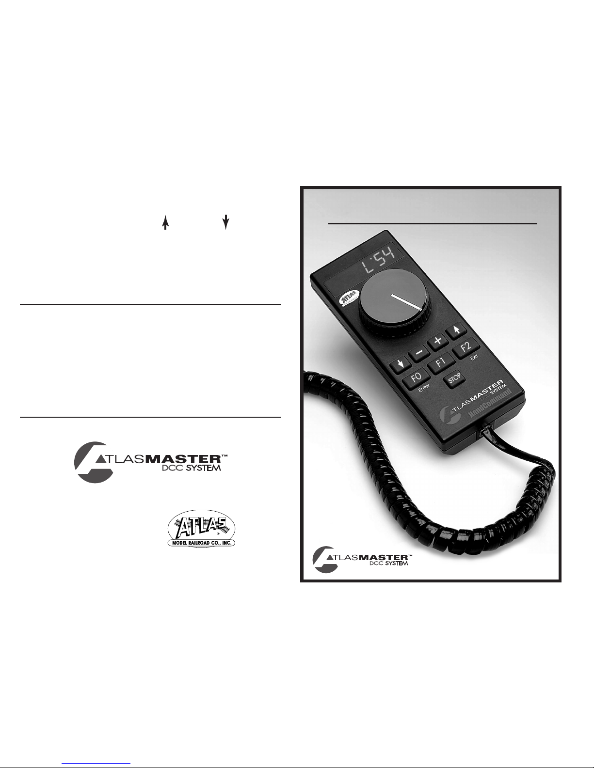
INSTRUCTION MANUAL
FOR TECHNICAL ASSISTANCE:
(908) 687-0880
www.atlasrr.com
dcc@atlasrr.com
LIMITED ONE-YEAR WARRANTY
Atlas Model Railroad Company, Inc. warrants that this HandCommand will be free from defects
in material and workmanship for a period of one year from the date of purchase. If this
HandCommand fails during the warranty period, carefully pack the item in the original carton,
together with the dated sales receipt, and return to: Atlas DCC Warranty, 378 Florence Avenue,
Hillside, NJ 07205. Defects due to misue, improper maintenance and/or abuse are not covered
by the warranty. Items that have been disassembled by the modeler or anyone other than an
authorized Atlas repair person are not covered by the warranty. This warranty gives you specific legal rights and you may also have other rights which vary from state to state.
ITEM #331
Removing a locomotive from a consist
1. Select the address of the locomotive to be removed from a Consist.
2. Enter the Menu by pressing the Forward, , and Reverse, , buttons.
3. Use the + or – buttons to select "
nu-", and press Enter. The display will blink.
4. Press Enter again to remove the locomotive from the Consist.+
Page 2

TABLE OF CONTENTS
Getting Started.................................................................3
Using the Atlas Master DCC HandCommand....................... 4
Locomotive Addressing....5
Running Your Locomotive...................................................5
Controlling Speed...6
Changing Directions...6
Activating Functions...7
Emergency Stop...8
Recalling Locomotives (“stack” function)............................8
The Menu System..............................................................9
Accessing the Menu...10
Menu Selections...10
Controlling Turnouts...10
Setting Speed Steps...11
System Settings...13
Consisting........................................................................ 14
1
INTRODUCTION
Congratulations for purchasing Atlas’ new plug-n-play DCC throttle!
Everything you will need to get started using the HandCommand is
included; there are no special cables to make, no searching for hard-tofind connectors or wire crimping necessary! Enclosed are: One Atlas
Universal Panel Connector (UPC) that you can mount anywhere on the
fascia of your layout for remote use of your HandCommand (see separate instruction sheet, included), 7' Xpress-Net cable wire which is used
to connect the UPC to the Commander or other command station you are
using, and a 6' coiled cord to connect your HandCommand to the UPC.
The enclosed Atlas HandCommand is a walk-around throttle designed to give you the
functionality of the Atlas Commander, without the ability to program decoders. You
can add up to five HandCommands to a Commander, for complete control of any size
layout. This manual will give you all the information you need to use the
HandCommand with the Atlas Commander or other DCC Command Station that is
XpressNet-compatible. Please check our web site at www.atlasrr.com for any pertinent updates to this or other Atlas Master DCC components.
ATLAS MASTER DCC SYSTEM COMPONENTS
The following is all you need to get started running your trains in
Digital Command Control:
1. Commander
*: Item #330 - For complete control of your trains. Controls
up to 99 locomotives and 99 accessories (i.e., turnouts). Supports up to
five HandCommand throttles and three additional Power Stations (for
added power). Control up to three functions per decoder (available
functions depends on the capability of your decoder).
2. Generator
*: Item #335 - Provides power to the Atlas Commander. Also
makes a great power supply for your turnouts and other accessories.
2
Page 3

3. Decoder*: Item #340 - Atlas offers an HO scale multi-function DualMode Decoder™ that, once installed, allows you to easily switch the
operation of your locomotive from analog to digital mode. This function
enables you to run your decoder-equipped engines on an analog layout
without the typical speed differential. N scale multi-function decoders are
also available. Some HO & N scale Atlas locomotives have decoders
factory-installed, for your convenience. See our web site for further
details. www.atlasrr.com
* The Atlas Master DCC System components conform to the NMRA DCC
standards and are also compatible with items from other DCC manufacturers.
GETTING STARTED
In order to function, the HandCommand must be connected to a Commander or
other command station that supports XpressNET technology (see shaded box on
right for definition of XpressNET). This connection can be made directly using the
7' XpressNet cable (see instructions below) or through an installed Universal
Panel Connector (UPC; see separate usage instructions enclosed), using the 6'
coiled cord. Using the UPC gives you the ability to use your HandCommand from
a location that is remote from your Commander.
Connecting the HandCommand to the Atlas Commander (or other
Command Station)
The Atlas HandCommand is designed to work with the Atlas Commander or any
system that supports XpressNET technology. You must have an Atlas Commander
or other Command Station to use the HandCommand; it cannot function independently.
3 4
Connecting the HandCommand to a Commander
The HandCommand connects to the Atlas Commander via the XpressNET connector on the back of the Commander. The connection is made with a 6-conductor wire having a six-pin RJ25 connector; a 7’ wire is enclosed. Up to five
HandCommand throttles may be connected to one Atlas Commander. See UPC
instructions for diagram.
XpressNET is a high-speed digital network based upon the industry standard
RS-485 protocol. The Atlas Commander uses XpressNET to communicate
between its high-speed components, such as the HandCommand. XpressNET
communicates at 62.5 thousand bits per second (nearly 4 times faster than its
closest competitor). It is the highest performance network in widespread DCC
use and all its protocols are freely available to both the industry and the hobbyist.
XpressNET is an industrial based technology, which can be setup in an infinite
number of possibilities, making it simple to setup and control any layout, large
or small.
See separate instructions for installing and using the Atlas Universal Panel
Connector.
USING THE ATLAS HANDCOMMAND
Buttons And Their Function
Dial - Used to control the speed of the selected engine.
and - Used to select the direction of the selected engine. Press both but-
tons together to access the Menu system.
Stop - Press this button to turn the track voltage on or off. Also press this button to restore power to the track after removing a short from the track.
Page 4

F0, F1, F2* - Used to control locomotive and accessory decoder functions. They
are also used for Menu operations.
When in the Menu, F0 functions as the Enter button and F2 functions as the
Exit button.
* The number of accessible functions depends on the capabilities of the decoder installed in
your locomotive.
"+" and " -" - Used to select the address of the locomotive (or Accessory
Decoder) you wish to control. When in the Menu, used to select Menu options or
to set parameters.
Understanding Locomotive Decoder Addressing
Each decoder-equipped locomotive has an address. The address is how the
HandCommand identifies which locomotive it is controlling at any given time.
Using the HandCommand you can easily control the speed, lights, and other
functions (if available) of up to 99 locomotives!
Most decoders come set to the default address of “03.”
RUNNING YOUR LOCOMOTIVE
When you connect the HandCommand to an Atlas Commander or other XpressNET
compatible command station, the display will default to the Locomotive display,
Lxx (xx is a locomotive address).
Select the locomotive you desire to control using the + or - buttons. Once you’ve
reached the desired address, you may acquire the locomotive by adjusting the
speed, changing the direction of the locomotive, or activating a function.
Controlling the Speed of Your Locomotive
The speed of the selected locomotive is controlled with the dial. Turning the dial
clockwise increases speed, turning it counter clockwise decreases the speed. In full
counter clockwise (ccw) position the locomotive stops and full clockwise position
sets maximum speed.
5
Changing Directions
The and buttons are used to control the direction of the selected locomotive:
Key
Display
Forward - A dot will appear to the
upper left of the centermost LED.
Backward - A dot will appear to the
lower left of the centermost LED.
The direction of travel changes only after the key is released. The display will
show the selected direction.
If you change the direction while the engine is still moving (speed dial not fully
ccw), the locomotive will decrease speed (brake) with the preset deceleration setting until it comes to a full stop and then accelerate in the opposite direction with
the preset acceleration setting. For more information on acceleration and deceleration settings (and programming same), see decoder documentation.
Activating Functions*
Buttons F0, F1 and F2 are used to activate functions on the selected locomotive
and to control turnouts or other accessories via an accessory decoder. (For information on controlling your turnouts or accessories, please see page 10.)
Function zero - F0 - controls the front headlight and rear light (these lights may
be configured for directional or independent control).
Pressing the button once activates the function, and the second press turns it off.
All functions can be activated or de-activated independently of each other so you
may have two or three functions on at one time, if desired.
L .03
L .03
6
Page 5

The user may configure function one - F1, function two - F2, function three - F3,
and function four - F4. Examples of additional functions are sound (bells, horn,
whistle) ditch lighting, or strobe lights. Consult your decoder’s manual for information on installing and using additional functions.
To control F3 or F4: Press and hold a direction button, Forward or Reverse .
Press F1 to control Function three. Press F2 to control Function four.
The display below shows if a function is active or not.
*The number of accessible functions depends on the capabilities of the decoder
installed in your locomotive.
Active
Function
Display
If function F0 is active, a dot is displayed to the
lower right of the leftmost LED.
If function F1 is active, a dot is displayed to the lower right
of the center LED.
If function F2 is active, the dot is displayed to the lower right
of the rightmost LED.
If function F3 is active, a dot is displayed to the lower right
of the center LED while a direction button is pressed.
If function F4 is active, a dot is displayed to the lower right
of the rigthmost LED while a direction button is pressed.
78
Emergency Stop
In case of a foreseeable train crash, operation can be stopped by pressing the
Stop button:
Key
Display
The display shows a flashing "OFF".
The power to the track is turned off.
Pressing the Stop key again restores power to the track.
All locomotives running prior to pushing Stop will start up and
accelerate to the last set speed.
If a short occurs on the track the display will display a flashing "OFF". Once the
short is cleared from the track, press the Stop button to restore power to the
track.
When the stop button is pressed after an emergency stop or after clearing a short
on the track, all trains resume operation at the speed they were set to prior to
the stop or short.
RECALLING LOCOMOTIVES
The HandCommand has a “stack” feature which remembers the last eight locomotives accessed. To recall a locomotive from the stack, press either the Forward
or Reverse button (depending on the direction the locomotive is traveling)
and then the + or - button to scroll through the stack until you reach the desired
locomotive. The stack remembers the last eight locomotives acquired; any locomotives acquired prior to the last eight are not accessible via the stack. For example, in a stack of 1,2,3,4,5,6,7,8, if you access another locomotive (ie., locomotive 9), the stack will forget locomotive 1 and remember 2,3,4,5,6,7,8,9.
L..03
F0
F1
F2
OFF
L..29
Stop
Stop
L.0.3
L.03.
L.0.3
F3
F4
L.03.
Page 6

10
Menu Selections
This menu is used to control turnouts, or control other accessories.
NOTE: You must have an accessory decoder attached to one or
more turnouts on your layout to use this function. For more about
controlling turnouts, see below.
This menu is used to select the speed steps of the selected
locomotive decoder.
This menu is used to change the system settings.
Controlling Turnouts
Accessory decoders, like your locomotives, require a unique address to allow
independent control. Most Accessory Decoders are programmed in groups of four.
I.E. (1,2,3,4), (5,6,7,8), (9,10,11,12), … Accessory decoders must be programmed just like a locomotive decoder (consult the instructions included with
your accessory decoder for programming directions). After the required programming you can use the Function buttons on your HandCommand to control
the turnouts as described on the next page.
1. Press both Forward and Reverse buttons at the same time to access the
Menu system.
(...continued at top of next page)
SPE
SY.S
9
Acquiring a locomotive that is currently running:
When selecting a locomotive, either directly using the + or - buttons or from the
stack, you may adjust the speed dial to approximate the locomotive’s speed.
When acquiring a locomotive directly, select the locomotive address on the display. Then press and hold the direction button and adjust the Speed dial to
approximate the speed of the locomotive, then release the direction button.
When recalling a locomotive from the stack, adjust the Speed dial prior to releasing the direction button. This allows you to recall a locomotive without an abrupt
change in speed.
.
THE MENU
The HandCommand has a Menu System which is used for the following settings and functions:
• Controlling turnouts • Adjust system settings • Setting speed steps
Accessing the Menu
Press both Forward and Reverse buttons at the same time to access the
Menu system. The display changes and now shows the last used menu. You may
scroll through the menu choices using the + and - buttons.
When you reach the desired menu, press the Enter button to access the settings
in that menu. Press the Exit button a second time to return to the locomotive display.
Page 7

11
Display What To Do
Press Enter to access the Turnout (switch) menu. Press the + or buttons until the Turnout menu is displayed, then follow the steps
below.
Use the + or - buttons to select the turnout (or accessory
decoder) address you desire to control. (Possible range is 1
through 99)
When you reach the desired turnout address, Press
F0 or F1 to control the turnout.
The direction the turnout throws will depend on how it is connected to the
Accessory Decoder. If the turnout throws in the wrong direction, reverse the two
control wires connected to the Accessory Decoder.
During the time you are in the Turnout menu, you can control the speed of the
locomotive that was last selected using the dial.
Speed Step Assignment
The speed range from a complete stop to maximum speed is divided in steps. The
larger the number of steps, the better the speed control resolution. (ie., the larger the number of speed steps the smoother the control of the locomotive.) The
Atlas Commander supports 14,28, and 128 Speed Steps and defaults to 28 speed
steps. Speed step settings are assigned for each locomotive and each locomotive
may be set to a different number of steps. Follow the procedure below to set the
speed steps for the locomotive selected on the display.
Setting Speed Steps*
1. Press Exit until you are back at the Locomotive address display [L ##].
Scroll using + and - until you arrive at the desired locomotive address.
2. To Enter the Menu System, press both Forward and Reverse buttons at
the same time.
12
Display What To Do
Press the + or - button until the speed step menu is displayed.
Press Enter to access the speed step menu.
The display shows the current speed step setting for the
selected locomotive address.
Press + or - until you arrive at the desired speed step (14, 28 or
128 are your options)
Once the desired speed step is displayed, press Enter to accept the
change, or press Exit to return to the Menu selection without
changing the speed steps.
* The selected locomotive must be stopped (Speed dial fully CCW) to change the
speed steps.
NOTE:
If the headlights on your locomotive blink on and off as the speed is changed, the
Commander is in 28 speed steps and the locomotive decoder is set for 14 speed
steps. If the lights do not turn on at all, the locomotive is set for 28 speed steps
and the Commander is set for 14 speed steps. The Commander defaults to 28
speed steps. If your locomotive returns to 14 speed steps after losing power, or
being removed from the track, the locomotive is configured for 14 speed steps.
To correct this, add 2 to the value in Register 5 and save the new setting. Consult
your system manual for programming procedures.
System Settings
The following system parameters can be edited or viewed:
• Version number of the HandCommand software (view only).
• Service number of the HandCommand. You will be asked to identify this
number if you call in for assistance with your HandCommand.
SPE
2.8
2.8
.4
Page 8

13
Accessing System Settings
1. Press and to enter the Menu system and use the + or - button to select
"SYS".
Display
What To Do
Press Enter to access the System Menu or press Exit to return to
the Locomotive Display.
This menu is used to display or change the HandCommand
XpressNET address. Press Enter to access this menu, or press Exit
to return to the system menu.
The XpressNET address range is from 1 to 31. Use the + or button to select an address.
Press the Enter button to accept the new XpressNET address, or
Exit to return to the System Menu selections.
This menu displays the HandCommand software version number.
This selection cannot be changed.
Press Enter to view the version number, or press Exit to return to
the System Menu selections. This selection cannot be changed.
This menu displays the Version number. Press Enter to view the
version number. This selection cannot be changed.
Press Exit to return to the System Menu selection. Press Exit
twice to return to the System Menu.
This menu displays the version number of the Master Commander.
Press Enter to view the Master Commander version number.
Press Exit to return to the System Menu selections. Press Exit
twice to return to the locomotive display.
SY.S
Y
.
Y .2
Y .3
Y
14
CONSISTING
(Multiple Unit Operations)
Consisting is operating or controlling several locomotives as if they were a single
locomotive or entity. For example, several diesels may be connected together to
provide more power for a steep grade. Consists are also known as Multiple Unit
lashups, or MUing. *(Please Note: Version 2.31 software for the Atlas
Commander does not support consisting. Please visit the DCC section of our website for an upgrade, at www.atlasrr.com)
Consist Setup Procedure
1. Select the address of the locomotive you wish to add to a Consist.
2. Set the direction that the locomotive will operate in the Consist.
3. Enter the Menu by pressing the Forward, , and Reverse, , buttons.
4. Use the + or – buttons to select "
nu", and press Enter.
5. Use the + or – buttons to select the address you wish to use as the Consist
address and press Enter.
Note: The Consist address can be the address of an actual locomotive or an
unused address.
6. Add additional locomotives by following steps 1 through 5.
If a locomotive is part of a Consist, the display will indicate this by replacing the
"L" with an "
n", or "n". If the display shows "n", the locomotive is the Lead loco-
motive. If the display shows "n", the locomotive is part of a Consist, but not the
Lead locomotive.
While a locomotive is part of a Consist, you may select the locomotive to change
any functions as desired. While making changes to a locomotive in a Consist, any
speed or direction changes will effect the entire consist.
(...continued at top of next page)
 Loading...