

Page 1

Page 2

Receiver Specifications ............................
3 Transmitt er Specifications
3
Model 200
-
PS Portable AC Supply .....................
4 Rechargeable Battery pack
5
Section 2 INSTALLATION ..................................
6 2-1 Introduction
6 2-2 General Information ..............................
6 2-22 Mobile Installations ...............................
9 2-28 Fixed Station Installations ..........................
13 2-29 Antennas
13 2-33 Fixed Station Antennas
14
Section 3 OPERATION ......................................
15 3-1 Introduction ...................................
15 3-2 Controls ......................................
15
3-
4 Power Supp ly On/Off, 220
-
CS/200
-
PS ..................
15
3-
5 Function Switch
15
3-
6 A. F.Gain ... ... ...............................
15 3-7 R. F.Gain .....................................
15 3-8 Band Selector and Tuning Dial, Model 210X ..............
15 3-9 Band Selector and Tuning D ial, Model 215X
17
3-
11 Carrier Balance
17 3-12 S-Meter Zero ...................................
17 3-13 Crystal Calibrator ................................
17 3-14 Proper tuning od Single Sideband Signals
17
3-
15 Voice Transmission ...............................
17
3-
16 Modula tion Level
18 3-17 ALC.........................................
18 3-18 CW Transmission
18 3-19 Heat Sink .....................................
18
Section 4 CIRCUIT THEORY ................................
20 4-1 Introduction
20
4-
3 Sensitivity .....................................
20 4-4 Selectivity .....................................
20 4-5 Oscillator Switching ..............................
20
4-
6 Transmitter Broadband Circuitry
24
4-
7 Receiver Broadband Circuitry
24 4-8 Alignment and Troubleshooting ......................
24 4-9 Voltage Charts ..................................
24 4-10 Signal Frequency Ranges and Local Oscillator Frequencies .. ...
25
4-
12 PC-200C — Second I.F. Amplifier, Second Mixer, Mic. Amp.
4-
13 PC-300D
-
Receiver Audio, Oscillator Switch .............
30
SWR Protect ...................................
32
4-
16 PC-600 Carrier Oscillator, Buffer Amplifier .............
36 4-17 PC-800C/1200 Rec e iver Input Tuning ...... ......... ..
38
Section 1 GENERAL INFORMATION .......................... 1
General Specifications 2
Model 220-CS Power Supply Console Specifications ......... 4
3-3 Power Supply On/Off, Mobile Operation ................. 15
TABLE OF CON TENTS
1-1 Introduction
1
3-10 Dial Set ....................................... 17
4-2 Receiver Input Circuit 20
4-11 PC-100C - First Mixer/First I.F. Amplifier ............... 26
S-Meter Amp. .................................. 28
4-14 PC-500D/520A - Pre-Am plifier, D river, Power Amplifier,
4-15 PC-400C VFO Board and Tuning Circuits ............... 34
4-18 PC-820 100 kHz Crystal Calibrator ................... 41
Page 3

2-1 Remote CW Transmit Switch for Atlas Transceivers
......... 8
2-2
Linear Amplifier connections for Atlas Transceivers
......... 10
2-3
Deluxe P lug
-
In Mobile M ount in g Kit I n stal la ti on
......... 11
2-4
Mobile Bra ck et Kit In sta lla tion ........... ... ... .....
......... 11
2-5
D.C. Power Connections ..........................
......... 12
2-6
Model 220
-
CS/200
-
PS Schematic Diagram ...............
......... 14
3-1
Front P an e l of ATLAS 210x ................ ........
......... 16
3-2
Rear Panel of ATLAS 210x/215x ....................
......... 16
4-1
ATLAS 210x/215x Modular Design and Plug
-
in P.C. Boards . . .
......... 21
4-2
ATLAS 210x /215x Block Diagram ............. ......
......... 22
4-3
Crystal Ladder F ilter Selectivity Characteristics ...........
......... 23
4-4 PC-
100C Schema tic Diagram .... ....................
......... 27
4-5 PC-
200C Schema tic Diagram .... ....................
......... 29
4-6 PC-
300C Schema tic Diagram .... ....................
......... 31
4-7 PC-
500D/520A Schematic Diagr a m ...................
......... 33
4-8A
Model 210x PC
-
400C Schem atic Diagram ... ......... ...
......... 35
4-8B
Model 215x PC
-
400C Schem atic (tuning section only) .......
......... 35
4-9 PC-
600 Schematic Diagram .................... .....
......... 37
4-
10A Model 210x PC
-
800C/1200 Sc li ematic Diagram . ..........
......... 39
4-
10B Model 215x PC
-
8000/1200 Schematic Diagram ...........
......... 40
4-11 PC-
820 Cryst al C alibrator Schematic Diagram
......... 41
4-12 PC-
9000 Transmitter Input Tun ing Schematic D iagram ......
......... 43
4-13 PC-
1010/1020 low Pass Filter Schematic Diagram .........
......... 45
4-14 PC-
1100A
SWR Bridge, Antenna Relay Scliematic D iagram . . .
......... 46
5-1 PC-
120 Noise Blanker Schematic Diagram ...............
......... 48
5-2
Model l0x Crystal Oscillator ........................
......... 49
5-3
Model 10X Crystal Oscillator Schematic Diagram
......... 50
5-4
Model MT
-
1 Transformer installation
......... 51
5-5 Model D D
-
6 Digital D ia l ... ... .....................
......... 52
Section 5
4-19 PC-900C Transmitter Input Tuning .....………………… ………………………............ 42
4-20 PC-1010/1020 Low Pass Filters ......... ......... .…………………………………………… 44
4-21 PC-1100A SWR Bridge , Antenna Rela y ......... .....……………………………………… 46
ACCESSORIES .................................... ………………………………………………………47
5-1 Model PC-120 Noise Blanker ....................... ……………………………………………47
5-2 Model l0x Crystal Oscillator ....................... ……………………………………………...49
5-4 Model VX-5 VOX .............................. ……………………………………………………52
5-5 Model DD-6 Digital Dial .......................... ……………………………………………….52
Figure
1-1 Atlas Model 21 Ox Illustrated with Optional 220-CS AC Console ......... 1
LIST OF ILLUSTRATIONS
5-6 M odel 210x/215x Chassis Wi ri ng ..................... inside back c over
Page 4
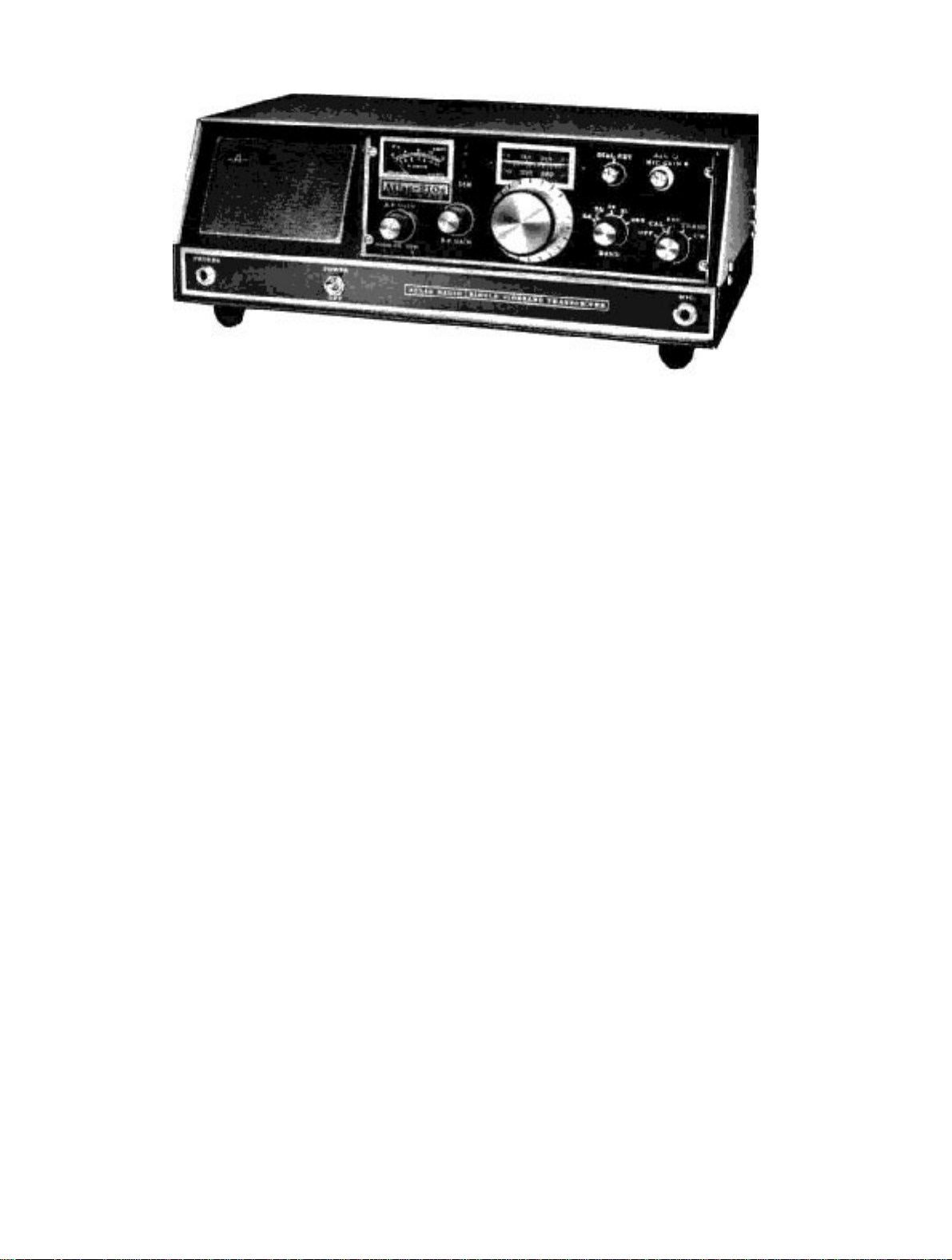
Figure 1-1. Atlas Mo del 210x Il lus tra ted with Optional 220-CS AC Console
SECTION 1 GENERAL
INFORMATION
1-1. INTRODUCTION
The Atlas 210x Transceiver is designed for single sideband and CW communications in the 10, 15, 20, 40, and 80
meter amateur radio bands. The Atlas 215x covers 15, 20, 40, 80, and 160 meters. They employ all solid state
circuitry, with modular construction. The conservative 200 watt power input rating will provide world wide
communications from fixed, portable or mobile installations.
Atlas Radio, Inc., is licensed by Southcom International, Inc. of Escondido, California, manufacturers of military
and commerci al radio equipment. With this agreement. Atlas Radio is able to bring the m ost advanced state-of- theart circuit designs to the amateur radio market. Les Earnshaw, founder and Director of R&D at Southcom
International, is considered to be one of the foremost solid state engineers in the world, effectively proved by the
rapid growt h o f S outh c o m I nt ernat io nal in the military and com m er cial radio markets o f t he Unit ed States, as well
as many other countries.
The hi gh perf orma nce a nd relia bil ity o f the At las tra n sceiv er is en hanc ed by t he fin est cra fts man ship, and a mo st
thorough quality control program. Our staff is made up of highly skilled assembly worker s, technicians, and
engineers, many of whom are active radio hams. Our service department, if and when needed, is dedicated to
making every Atlas owner a satisfied customer. Speaking for all the gang at Atlas Radio, we wish you many hours
of opera ting pleasure with your At las tran s c eiver.
73 Herb Johnson W6QKI President
Page 5

GENERAL SPECIFICATIONS
BAND COVERAGE:
ATLAS 21 Ox: Covers 80, 40, 20, 15, and 10 meter
bands, with internal VFO ranges as follows:
3500- 4000kH z
7000- 7500kH z
14000-14500 kH z
21000-21500 kH z
28400 - 29400 kHz
NOTE: The 10 meter band on the 210x may be easily
owner adjusted to cover any 1000 kHz portion of the
band.
ATLAS 215x: Covers 160, 80, 40, 20, and 15 meter
bands, with internal VFO ranges as follows:
1800 2100kHz
3500 4000kHz
7000 7500kHz
14000 14500kHz
21000 21500 kHz
FREQUENCY CONTROL;
Highly stable VFO common to both receive and
transmit modes.
13800 14900kHz
20600 21600 kHz
Note: The Model l0x will not oper a te on the 28.0
MHz band.
CIRCUIT DESIGN:
All solid state, 4 IC's, 18 t ransistors, 31 diodes. Single
conversion, 5520 kHz I.F.
MODULAR CONSTRUCTION:
Includes plug-in circuit boards for ease of
maintenance.
PLUG-IN DESIGN:
Transceiver plugs into the Deluxe Mobile Mounting
Bracket, or into the optional 220-CS power supply
console, making transfer or removal a simple
operation. All connectors are standard: SO-239
antenna jack, 1/4 in. phone jacks for Mic., CW key,
external speaker or headphones, and linear amplified
control.
FREQUENCY READOUT:
Dial s cale ca librat ed i n 5 kHz i n cremen ts on all band s
except 10 meters, where increments are 10 kHz.
Tuning knob skirt provides 1 kHz increments on all
bands except 10 meters, where increments are 2 kHz.
EXTERNAL FREQUENCY
CONTROL:
Rear so cket prov ides for plu g-in of ext ernal VFO or
crystal oscillator accessory for separate control of
transmit and receive frequencies, or for network and
MARS ope ration.
EXTENDED FREQUENCY RANGE WITH
CRYSTAL OSCILLATOR:
When the model lOx external crystal oscillator
accessory is used, frequency ranges are as listed in the
following charts:
1800 - 3000 kHz (Model 215x only)
3000- 5200kH z
5800 - 10000 kHz
POWER SUPPLY REQUIREMENTS
Operates directly from a 12 to 14 volt D.C. source
with negative ground (standard automotive system).
Current drain is 300 to 500 ma. in receive mode, 16
amps. peak in transmit mode. Atlas model 220-CS
power supply console and the model 200-PS portable
supply are available for AC operation.
FRONT CONTROLS:
Tuning D ial , D ial S et, Fun cti on S wit ch, Band Swit c h,
A.F. Gain, R.F. Gain, Mic Gain, Sideband Selector,
Calibrator On-Off, Dial Light Dimmer, ALC Control.
FINISH:
Black vinyl covered aluminum cabinet and bottom
cover, anodized aluminum panel.
WEIGHT:
6 Ibs. 14 oz. (3.1 Kg) net , 8 Ibs. 6 oz. (3.8 Kg )
shippi ng weight .
DIMENSIONS:
9'/2 in. (24.1 cm) wide, 3'/2 in (8.9 cm) high, 9Vi in.
(24.1 cm) deep overall.
2
Page 6

RECEIVER SPECIFICATIONS
CIRCUIT DESIGN: Front end design provides
exceptional immunity to overload and cross
modulation, matching or out performing the best
vacuum tube designs. Signals are converted directly
to the 5520 kHz I.F. without preamplification. Converter and product detector are double balanced diode
rings. IC's are employed in I.F. and AF stages.
SENSITIVITY: Requires less than 0.4 microvolts
for a 10 db signal-plus-noise to noise ratio on 160, 80,
40, and 20 meter bands; 0.4 microvolts on 15 meters;
and 0.6 microvolts on 10 meters. SELECTIVITY:
Crystal Ladder Filter, 8 poles. Bandwidth: 2.7 kHz @
6 db, 4.3 kHz @60db,9.2kHz@ 120 db!! Ultimate
rejection more than 130db!! Shape Factor 1.6.
IMAGE REJECTION: More than 60 db.
INTERNAL SPURIOUS: Les s than equivalent 1
microvolt signal. AGC CHACTERISTICS: Audio
output constant within 4 db with signal
TRANSMITTER SPECIFICATIONS
CIRCUIT DESIGN : Broadband design eliminates
transmitter tuning. Single conversion from I.F. to
output frequency produces minimum spurious and
mixing products. 2 section low-pass filters on each
band provide harmonic suppression equal to
commercial standards. Includes ALC and infinite
SWR protection.
FREQUENCY CONTROL: Internal VFO
automatically transmits on exactly the same frequency
that is being received. Rear socket provides for plugin of external VFO or crystal oscillator accessory for
separate control of transmit and receive frequencies,
or for network an d MARS opera tion.
POWER RATING: 200 watts P.E.P. input, and CW
input, (with 50 ohm resistive load and 13.6 volt D.C.
supply) on 160,80,40,20,and 15 meter bands; 120W
on 10 meter ba nd. P ower outpu t: 8 0 mini mum P. E.P.
and CW on 160, 80, 40, 20, and 15 meter bands; 50
watts minimum on 10 meter band.
variat ion from 5 microvo lts to more than 3 volts.
OVERALL GAIN: Requires less than 1 microvolt
signal for 0.5 watts audio output. (CW carrier, 1000
Hert z h eterdy n e) .
AUDIO FIDELITY: 300 to 3000 Hertz, plus or
minus 3 db. INTERNAL SPEAKER: 3 in., 3.2 ohm,
.68 oz. magn et. Rear jack permi ts plu g in of ex terna l
speaker or headphones. Headphones of 500 to 600
ohms are recommended. Headphones of a higher
impedance may be used, but will require a h ig h er A. F.
Gain setting. Lower impedance headphones will
require a lower A.F. Gain setting. When transceiver is
plugged into the AC power supply console, internal
speaker is disconnected automatically, and front
faci ng sp eaker on consol e be comes operati ve.
METER: Reads "S" units from 1 to 9, plus lOtoSOdb.
CALIBRATOR: Provides 100 kHz check po int s for
accura te dial se t ting.
RTTY /SSTV POWER RATING:
Approximately 90 watts P.E.P input (dependent
directly on ventilation of heat sink).
EMISSIO N : SSB: Lower sideband on 40, 80, and
160 meters. Upper sideband on 20, 15, and 10 meters
with Sideband Selector switch in NORM position.
Opposite with switch in OPP position. CW: offset
frequency.
UNWANTED SIDEBAND: More than 60 db down
at 1000 Hert z A F in put.
CARRIER SUPPRESSION: More than
50 db down.
THIRD ORDER DISTORTION:
Approximately 30 db below peak power.
HARMONIC OUTPUT: More than 35 db below
peak power.
SUPRIOUS AND IMAGE OUTPUT:
More than 40 db below peak power.
Page 7

CW KEYING: Manual send-receive.Semi-break-in
with CW accessory installed in AC power supply
console.
TRANSMIT CONTROL: Press to talk with Mic.
button, or manual tr an s mi t with Funct io n S witc h o n
front panel. Aut o mati c voic e co ntr ol wh en VO X
accessory is installed in AC power supply console.
MICROPHONE: Dynamic or crystal.
MODEL 220-CS POWER SUPPLY
CONSOLE SPECIFICATIONS
INPUT VOLTAGE: 110 or 220 volts AC, 50-60 H z .
INPUT POWER: 10 watts average, receive. 250
watts transmit peak.
OUTPUT: Low current line: 13.6 volt s regulated, Vi
amp. High c urrent line: 13 volts at 16 amps.
SPEAKER: 3x5 in. oval, 1.1 oz. magnet, 3.2 ohm
voice coil.
FINISH: Textured Vinyl bonded to aluminum,
durable and scr a tch resi sta nt.
Plug requirem ent: standa rd % in. diam. 3 circui t
phone plug.
AUDIO FIDELITY: 300 to 3000 Hertz, pl us or minus
3 db.
METER: Reads power amplifier collector current, 016 amperes.
LINEAR AMPLIFIER CONTROL:
Rear jack provides for keying of linear, and ALC
control fro m lin ear.
PLUG-IN DESIGN: Transcei ver plugs dir ectly int o
power supply console, automatically makes
connections for antenna and front facing speaker.
Mic. jack an d headp h on e jack a re brought out to fro n t
panel.
ACCESSORIES: Space under transceiver permits
addition of VOX unit. Space in rear permits addition
of semi-break-in CW.
DIMENSIONS: 15-1/2 in. (39.4 cm) wide. 5-5/8 in.
(14.3 cm) high. 9-1/2 in. (24.1 cm) deep.
WEIGHT: 17 Ibs. (7.7 Kg) less transceiver. 20 Ibs.
(9.1 Kg) shippin g w eig ht.
MODEL 200-PS PORTABLE AC SUPPLY
INPUT VOLTAGE: 110 or 220 volts
AC, 50-60 Hertz.
INPUT POWER: 10 watts ave rage, receive. 250 wa tts
transmit peak.
OUTPUT: L ow current line: 1 3.6 volts regu lated, Vi
amp. High current line: 12.5 volts at 16 amps.
INCLUDES: On-Off switch, Fuses, AC cord, and
D.C. Cable with conn ector for transceiver.
DIMENSION: 5-1/4 in. (13.3 cm) wide, 3-1/2 in. (8.9
cm) high, 6-1/2 in. (16.5 cm) deep.
WEIGHT: 7 Ibs. 4 oz. (3.3 Kg ) less transceiver. 10
Ibs. (4.5 Kg) ship pi ng wei gh t.
Page 8

RECHARGEABLE BATTERY P ACK
Globe Ba t ter y Di vi sio n, Gl ob e-U ni on In c., P.O. Box 5 9 1, Mi lwa uk ee, W i s. 53 201 , manu fa ctu res a "G EL -CEL L"
rechargeable Battery Pack, Model GC1400 which will operat e the Atlas transcei vers for a number of hours, with
operat ing time d eter mined by re ceive-tra nsmit rati o, and modulation l evel. The ba ttery has a n Amphere -Hou r
rating of 7.5 A.H. It comes in a simulated leather case with shoulder strap, and includes an AC charger.
Your Atl a s deal er ma y ha ndl e Gl obe pr odu ct s. Al so , it is ant ic ipat e d tha t Atl as Ra di o may ha ve th e GC1 40 0 pack
available for Atlas dealers. Otherwise, you may contact Globe directly for reference to a Globe dealer.
Page 9

SECTION 2
INSTALLATION
2-1. INTRODUCTIO N This secti on pr ovides instructions for mobile, portab le , or fix e d station
installations of the
Atlas 210x/215x transc eivers.
22. GENERAL INFORMATION
2-3. D.C. POWER. The Atlas transceiver is designed to operate on a power source of 12-14 volts D.C. Power can
be delivered to the transceiver via the Deluxe Mounting Kit (DMK), D.C. Cable (DCC), Cigarette Lighter Cable
(CLC), Portable Ba tt ery Pack, 220-CS AC Console, or 200-PS Portable AC Supply.
2-4. AUTOMOTIVE D.C. ELEC TRICAL SYSTEMS. The D.C. electrical systems in automobiles may at times
generate high voltage transients (spikes of voltage superimposed on the 12-14 volt D.C. system). These transients
may be caused by faulty brushes in the starter motor, alternator or generator, or loose wiring, and can represent a
possible hazard to the semiconduct ors in the transcei ver. For this reason, we strongly urge that you read the
following note s an d follo w the m car e full y.
(a) Clean the battery terminals and clamps, and tighten the cl amps s e curely .
(b) Tighten battery cable terminals where they attach to the engine.
(c) Inspe ct batter y cables an d terminals for co rr osion or w ea r . Replac e them if th ey l ook questi onable.
(d) Check battery condition frequently, especially when it approaches its warranty age limit. Use a protective
silicone grease on the terminals to inhibit corrosion.
(e) Check the alte r nator and regulator connections for tightness. Check primary ignition wiring, horn wiring,
light s, etc.
(f) Measure the char ging volta ge from t h e alter na t or with the engi ne r unning at abou t twice i d ling speed. Voltage
at the batter y te rminal s s hou ld measu re 13 volts mini mum, 14 .5 volts ma ximum. Co nsult you r a u t o - electri c
service shop if correction is required.
2-5. DELUXE MOUNTING KIT (DMK). The Deluxe Mobile Mounting Kit is a plug-in unit designed for easy
removal of the Atlas transceivers. All D.C. power connections are made to the DMK and all necessary hook-up
cables, including the D.C. battery cable with polarity protection, circuit breaker, and hardware, are part of the kit.
2-6. D.C. CABLE (DCC). The D.C. Cable (DCC) is designed with built-in polarity protection and overload
protection. Thi s cable is availabl e from Atlas deal ers and can be used wit h the Mobile Brack et Kit (MBK) or a
portable battery pack.
27. CIGARETT E LIGHTER CABLE ( CLC). Th e Cigarette Li ghter Ca ble is d esigned for u se in tho se instances
when D.C. pow er is requi r e d, and th e tr anscei v er ha s not been in s t a lled in the auto mo bi l e using t h e D MK or MBK
kits. T he cabl e has a spe cial ci gar ette li ghter plug o n one end, and a tran scei ver power pl ug on the ot her . Polar ity
and ov erload protection is included wit h t h e ca ble.
2-8. POR TABLE BATTERY PACK . Th e 7.5 ampere hour Portable Battery Pack provides 12 volts D.C. power via
portable rechargeable batteries. Connections from the bat tery pa ck to the t ranscei ver are ma de with t he batte ry
pack cable. All necessary plugs arc provided.
2-9. 220-CS AC CONSOLE. The 220-CS AC Consoles are available through Atlas dealers, and provide all the
D.C. power required for the Atlas transceivers The 220-CS operates from either 110 volts AC or 220 volts AC,
selected by changing fuses. A Microphone jack, Headphone jack, and antenna connector are also provided on the
console.
Page 10

2-10. 200-PS PORTABLE A C SUPPLY. The model 200-PS AC Supply is designed for portable and utility servi ce
where t h e wei g ht and si ze o f the del ux e AC con sol e i s not de sir ed. It 's co mpa ct si z e and li g ht wei gh t mak e i t id ea l
for the traveler, and yet it will do a completely adequate job in full time duty at the home station. It has a slightly
small er p ow er tra n sfor m er tha n th e AC co nsol e , whi ch r edu ce s D.C . i nput po wer a bou t 5 per cen t, bu t pea k po wer
with voice m odulat ion is t he same as with th e larg er trans form er. Also, t he 2 00 -PS does not c ontain a speake r, so
the one built into the transceiver is used. The 200-PS operates on either 110 volts AC or 220 volts AC, selected by
chan gi ng fuses.
It is anticipated that a pl astic or simulated leather carry ing case will be available from Atlas Radio for the 200-PS
supply as well as for the transceiver in the near future.
2-11. TRANSMISSION LINE IMPEDANCE MATCHING. Proper impedance match between the coaxial feedline
and the antenna system is considerably more important with the broadbanded solid state amplifier than with tube
type transmitters, which generally have a Pi-type matching network. The SWR should be as low as it can be in
order to permit full power operation. As SWR increases, power output from the Atlas transceiver decreases
approxim ately as indicat ed in the following table.
TABLE 2-1 . S W R V ERSUS OUTPUT
SWR APPROXIMATE
OUTPUT
1.0
100 watts
1.1 98 watts
1.2 95 watts
1.3 90 watts
1.5 80 watts
2.0 50 watts
3.0
20 watts
2-12. AMMETER READINGS. The ammeter on the Atlas transceiver provides an excellent indicator of
impedance mat ch. In CW tran smit mode, the Mic . Gain control b ecomes the Carrier Insertion control . With a
close match you will be abl e to run the am meter up to 1 2 amps or mor e (with supply voltage of 13.6 VDC or
117/230 VAC).
2-13. INFINITE SWR PROTECTION. T he Atlas tran sceiver has a bu ilt-in refl ecto-meter which automati cally
reduc es tran smitter drive a s SWR i ncrease s. Thi s makes t he power transi stors nea rly i mmune t o damage from
mismatched loads.
2-14. SWR MEASUREMENTS. A bridge for measuring Standing Wave Ratio (SWR) is very useful and
strongly recommended for checking impedance match. Use the follo win g pr oce dur es .
(a) Switch the bridge to "Forward" or "Sensitivity position.
(b) Set the sensitivity control on the bridge to maximum clockwise position.
(c) Set Mic. Gai n o n Atla s tra n scei v er to min i mu m.
(d) Set the transceiver Function Switch to CW mode.
Advance Mic. Gain until meter on bridge reads just full scale. (Mic. Gain is Carrier Insertion control in CW
(e)
mode).
(f)
Swi tc h brid g e to "SWR" or "Reflec ted" position for the S WR read ing.
(g)
Tune the tra nsceiver up and d own in frequency u ntil you locate minimum SW R. This will indicate the
resonant frequency of the antenna, and also the SW R at that frequency.
(h)
Switch the transceiver back to REC. mode. See Caution note, next page.
NOTE
High SWR will not damage the
Atlas tr ans ceiver. You m ay f eel
free to operate regardless of the
SWR. Only power input and
output will suffer. Reflected
voltag e wi ll n ot c ause damage.
Page 11
OPERATE TH E TRANSCEIVER IN CW MODE FOR ONL Y SHORT
PERIODS 0V TIME, JUST LONG ENOUGH TO MAKE THE SWR
MEASUREMENT. CHECK HEAT SINK TEMPERATURE DURING
SWR TESTS, AND IE IT IS GETTING QUITE WARM TO THE
TOUCH, LET THE RIG COOL FOR A FEW MINUTES BEFORE
CONTINUING.
2-15. MICROPHONE CONNECTIONS. The microphone may be either a dynamic or crystal type. A low impedance
Mic. will work, but will require higher setting of the Mic. Gain control, and may require closer speaking. If a
dyna mic Mi c. is s elect ed, i t sh ould prefer abl y be t he hi gh imp edan ce t ype. The ch oice of mi crop hone s is i mpor tant
for good speech quality, and deserves careful consideration. Select a high quality Mic. with smooth response from
300 to 3000 Hertz or more. An excellent choice is the Shure 404C hand Mic. The plug required for the Mic.
connector is a standard 1/4 inch diameter, 3 conductor type. The tip connection is the keying circuit for press-to-talk,
the ring conn ection is for the shielded Mic. lead, and th e sleeve or b arrel is the com mon ground terminal .
216. VOICE OPERATED TRANSMISSION (VOX). Most press-to talk microphones arc short circuited when the
button is not pressed, if the VOX accessory is installed in the AC console, this feature must be disabled. Refer to
instru ct i on s tha t com e wi th th e Mi c. Ope n th e cas e and lo ca te t he s wit ch c ont a ct s that shor t th e Mic c ir cui t wh en t he
button is not pressed, either disconnect the leads, or bend the contact so they do not make.
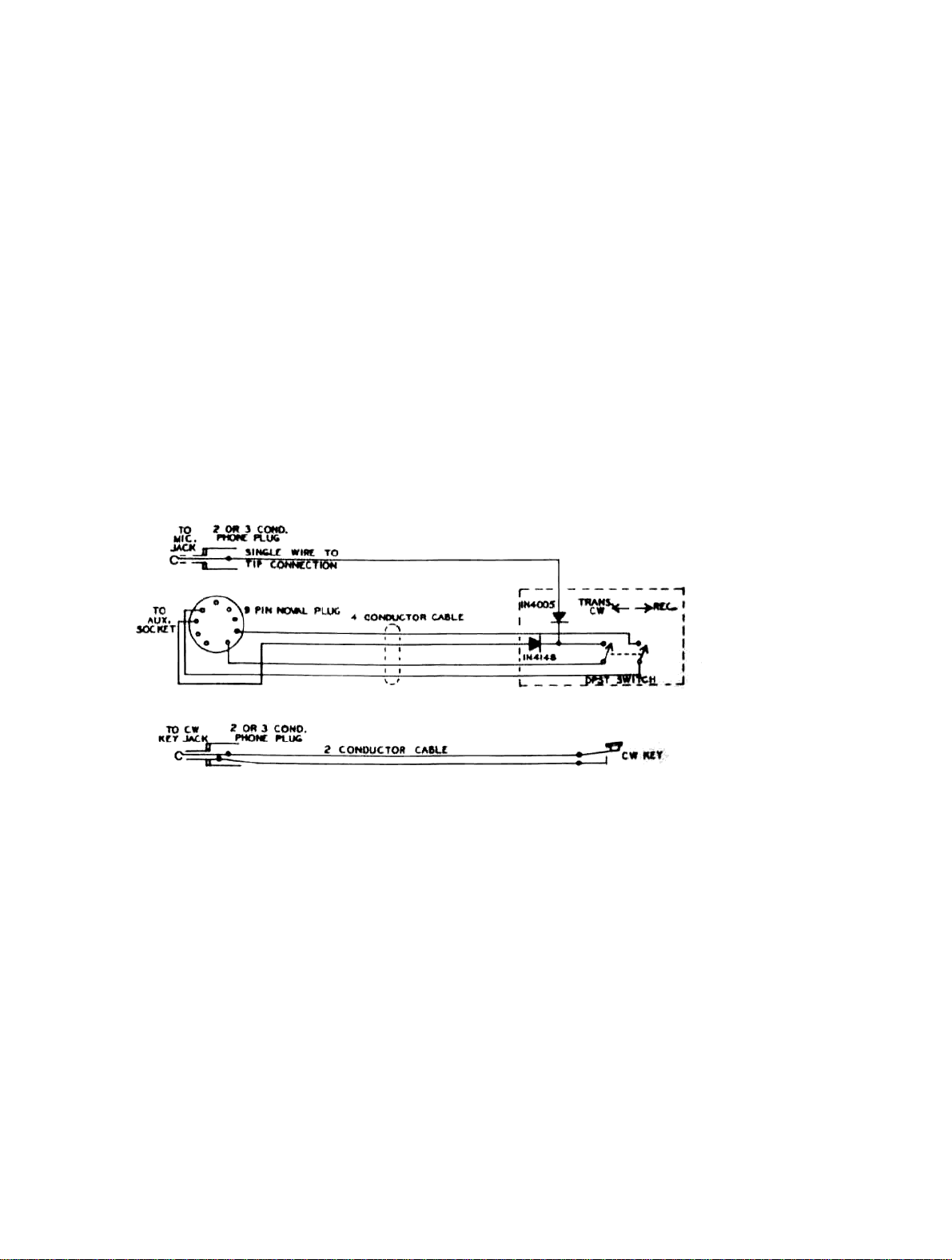
2-17. CW KEY. A jack on back of the transceiver is provided for insertion of a standard 1/4 inch diameter 2
conductor phone plug. Connect the CW key to this plug with a 2 conductor cable. The sleeve connection goes to
chassis grou nd. Keyi ng potential is less than 10 volts, positive, and dra ws less than 5 milliampères. Any of the
electronic keyers presently on the market will operate satisfactorily.
2-18. REMOTE CW TRANSMIT SWITCH FOR ATLAS TRANSCEIVERS.
The Atlas tran sc eiv er s hav e a fu nction switch which pr o vi des f or switching into the C W T r ansmit m ode. H o w ever , it
requires switching from the RLC. to TRANS., and then to the CW position. This procedure is rather awkward, and
the circuit shown below (Figure 2-1) provides a more convenient system.
CAUTION
Figure 2-1. Remote CW Transmit Switch for ATLAS Transceivers
8
Page 12

The remote switch can be a double pole, single throw toggle switch, and may be installed on a bracket or in a small
utility box alon g with th e two diod es. Oth er parts requ ire d are two phon e plu gs, a 9 pin Noval p lug, a 4 conduct or
cable, and a single insulated conductor.
The remote switch unit may be secured near the CW key, or possibly attached to one side of the key base,
permitting quick and easy switching to the CW Tra n smit mo d e.
Operatio n of the circuit is as follows:
When the switch is closed, the single conductor wire coming from the MicJack is grounded through the 1N4005
diode, a nd th e swi t ch to pi n 4 or th e E XT . OS C. socket. T hi s causes t he r el ays in t he t ra n sce iver to cl o se, plac in g
the transceiver in transmit mode. At the same time, the lead coming from pin 9 is grounded through the 1N4148
diode, thus disabling the Mic. Amp., and preventing voice modulation of the CW signal.
The other circuit of the 2 pole switch connects the +13 volt line from pin 8 to the +CW lead going to pin 1 of the
EXT. OSC. socket. This causes the carrier oscillator frequency (NORM. SB only) to move about 800 cycles up
into the filter passband, thus providing automatic off-set frequency during CW transmission.
2-19. EXTERNAL OSCILLATOR SOCKET. This socket is a 9 pin Noval installed on the back of the
transcei ver, and is for plug in of the Atlas Model lOx Crystal Oscill ator accessory, Model 206 External VF O , or
the Model DD-6B-C Digital Dials. Jumper wires are factory installed on this socket, and must be removed if any of
these accessories are to be used. 2- 20. AUXILIARY SOCKE T. This so cket is also a 9 pin Nov al, and is for control
of a Linear Amplifier or VX-5 or VX-5M CW Semi-breakin.
2-21. LINEAR AMPLIFIER CONNECTIONS. Figure 2-2 illu strates h ow to connect a l inear ampli fier to the
Atlas transceivers. ALC output from the linear may be connected to Pin 4 on the AUX. socket plug. The ALC
control voltage from the linear MUST b e positive going. Most linears with an ALC output circuit ar e negative
going. If this is th e case with your li near , and you wi sh to utili ze ALC cont rol from t he linear, it will be nece ssar y
that you modify the linear ALC circuit. This will usually consist of reversing one or two diodes in order to generate
a positive volta g e c ontrol in stead of ne ga tive.
In view of this requireme nt, you may choose to use the ALC system of the Atlas tra nsceiver alone. Mos t linears
will operate to the full legal power limit with little or no distortion.
2-22. MOBILE INSTALLATIONS
2-23. DELUXE PLUG-IN MOBILE MOUNTING KIT.
This kit includes :
(a) 6'/2 foot D.C. power cable; (b) 25 Amp. Circuit Breaker; (c) Black anodized aluminum plug-in housing; (d)
Two 9-inch and two 12-inch cadmium plated steel mounting bars;
(e) 3 inch wide rear bracket; (f) Package of screws and terminal lugs. Refer to Figure 2-3 for typical
transmission hump and under dash mounting arrangements.
1. The r ear br a cke t( s)) s hou ld be a ngl ed a s stra i ght ba ck as p os sibl e in or der to gi ve g ood sup por t for pu shi ng and
pulling the transceiver in and out of the mount.
2. The mounting brackets must be cut and bent to suit the installation, each being unique. Try different positioning
and select the o ne for best ease of op eration, and l east interferen ce with automo bile controls. T hen carefully
measur e ea ch brack et for l ength and a ngl e of ben d on it s t oot. Ben d as r equir ed. After be nding the bra cket s,
they may be painted with flat black to match the anodized aluminum parts, if desired.
3. Remove the acorn nut and hex nut. Sl ip bracket over screw, and replace only the acorn nut.
4. Secure brackets to car with No. 14 sheet metal screws. Tighten screws and nuts securely. No. 10 screws are also
furnished in case the No. 14 screws are too large.
5. Antenna connection is made by standard coax connector to the coax jack on the rear of the Deluxe Mounting
Kit.
6. An e xternal s peaker may be co nnecte d a s f ol lows: L ocate the speaker plug on the back o f t he mobile moun t, just
above the Mic. plug. Clip out the wire jumper g oing from the ti p lug to the ring lug . This will disc onnect the
internal speak er. Connect the ext ern a l speak er from t h e tip lug to the ground lug. Impedance should be 4 ohms.
Page 13

7. Black anodizing provides a very durable finish, much better than paint. However, the ano-dized surface is an
electr ical in sulati on. I n ord er to en sur e ele ctrica l bo ndi ng bet ween t he tra ns ceiv er and t he ca r cha ssi s, shak epr oof
washers must be used under all screw heads. They will cut through the anodizing. Scraping the an odizing off
aroun d the juncti on poi nts on the r ear brack et(s) is al so reco mmended. Poor grou nding may l ead to tra nsmitt er
instability, which will cause a regenerative or self oscillating condition. If there is any question of adequate
grounding, connect a copper braid or strap from the antenna bracket on the mobile mount to the nearest chassis
ground, eith er t h e bulkhea d or transmi s sion hump.
8. T he power cable s hould b e run fr om the mobil e mount t hroug h the bu lkhea d into t he eng ine com part ment. I t
should then be connected to the positive and negative terminals as close to the battery as possible. The best way
to conn ect dir ec tl y to t he ba tt er y ter mi nal po sts i s b y dri lli ng a nd ta pp in g fo r a 1 0 -32 or 10 -24 mach in e sc rew .
The red lead goes to the positive terminal, and the brown to the negative. (Or the white is positive and the black
is negative.)
9. The 25 ampere circuit breaker supplied with the kit should be installed in series with the positive lead. It is best
to mount it clo se to the battery en d of the cable, at so me convenient place o n the side of a metal pan el or
bracket. She et metal scre ws are supplie d for this purpo se. It is not imp ortant that th e metal case o f the circuit
breaker be grounded, since there are no connections made to the case. Cut the positive red power lead, install
No. 10 terminal lugs, and secure firmly to the circuit breaker with washers and nuts. Solder the terminal lugs.
The advant age of connecting directly to the battery posts is that loose battery clamps will then not a ffect the
NOTICE
transcei ver connections, and the danger of intermitten t voltage spikes is reduced. If drilling and tapping the b att ery
posts is not practi cal, then co nn e ct the lea d s to the engi ne end of the hea vy b a tter y cables. The negative cabl e will
usually be found going to a grounding bolt on the engine bloc k, and the positive cable usually goes to a bolt on the
starter solenoid. Use proper terminal lugs at these points for connecting the leads. Battery clamps and terminals
shoul d b e cleane d a nd ti ghtene d periodica l ly. Anti-corrosion gr ease is a good recom m e ndation. All oth er electr ica l
connect ions under the hoo d: alternator, regulator, ignition coil,etc. ,should also be checked and tighte ned.
Figure 2-2. Linear Amplifier Connections to ATLAS Transceiver
10
Page 14
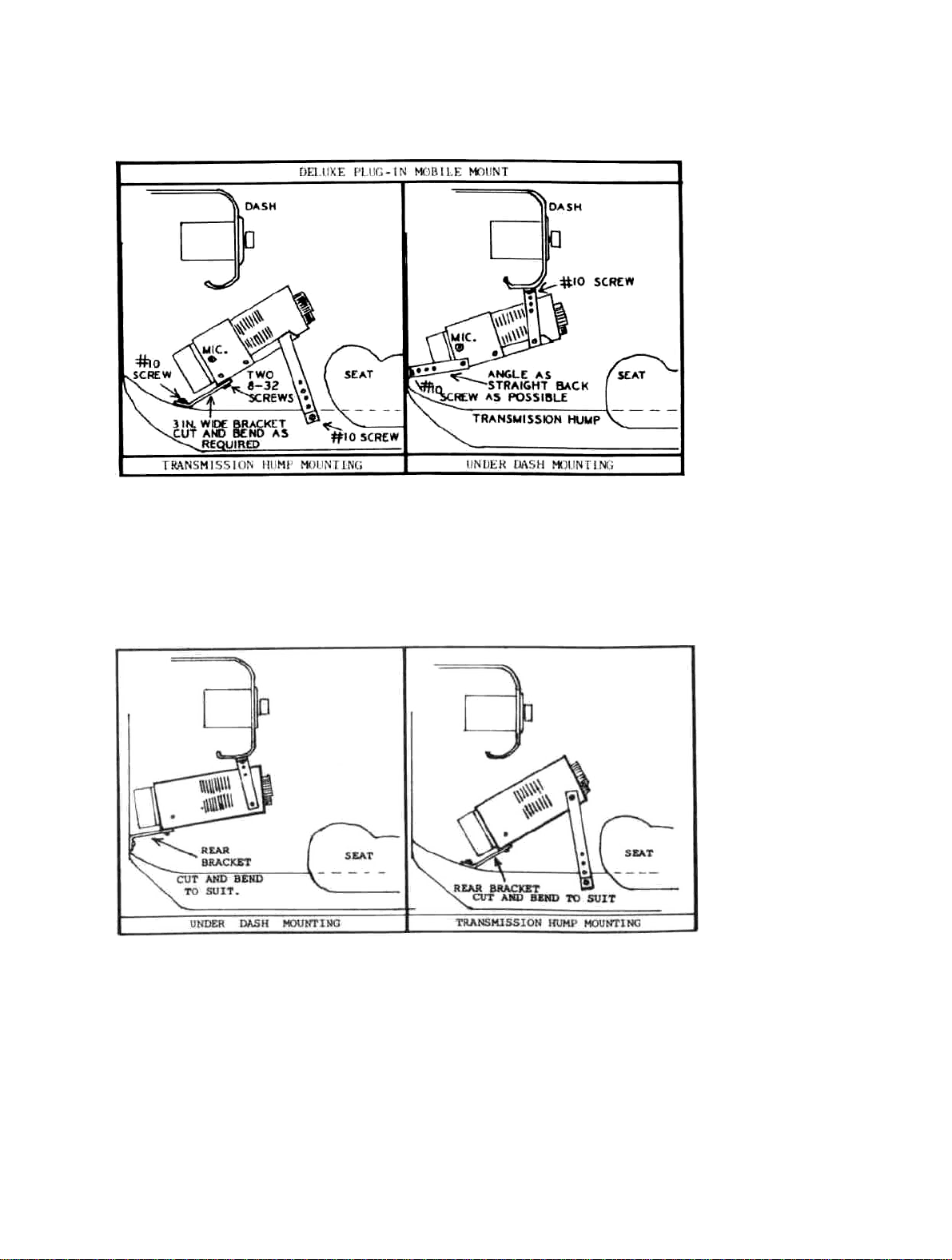
Figure 2-3. Deluxe Plug-in Mobile Mounting Kit Installation
2-24. MOBILE BRACKET KIT (MBK). This kit includes: One 9-inch and two 12-inch cadmium plated steel
mounting bars with scr ews. Figur e 2-4 illustrat es how the trans ceiver can be hun g under the dash, or mounte d over
the transmis sion hump. Each in stallation is different, so thi s must be left to the individua l. Consult your dealer or
friends with mobile experience if need be. The brackets can be cut easily and bent as required. The smaller No.
6x3/4 inch s crews are for at t a c hing the brack ets to the sides or bottom of the t r anscei ver. Th e y will re pl ace the No.
4x1/4 inch screws that came in the transceiver, thus allowing for the 1/8 inch thickness of the bracket. The No. 6
scre ws wi ll ma ke t he br a cke t s mor e se cur e tha n the or igi na l No. 4's woul d. T he No. 14 s cr ew s are f or s ecu rin g th e
brackets to the under side of the dash, or to the transmission hump. No. 10 screws are also furnished in case the
No. 14 screws are too large.
Figure 2-4. Mobile Bracket Kit Installation
2-25. INSTALLING D.C. POWER CABLE. The power cable should be run from the transceiver, through the
bulkhead, and connected as close to the battery as is practical. The best way is to connect directly to the battery
posts. Drill and tap into the lead terminal posts for 10-32 machine screws, and secure No. 10 terminal lugs under
these screw heads. The advant age of doing this is that even if th e battery clamps work loose, it will no t
11
Page 15

affect the transceiver connections, and the danger of intermittant transient voltage spikes will be reduced.
If drill ing and tapp ing the batt ery posts i s not practi cal, then co nnect the lea ds to the eng ine end of th e battery
cables. The negative cable will usually be found going to a bolt on the engine block, while the positive cable
usually goe s to a bolt on th e start er sole n oid. U se pr op er ter m inal lu g s at the s e poi nt s for co nne cti ng th e l ead s. T he
red lead goes to positive and the brown lead to negative. (If power cable has black and white leads, the black is
negative, and the white is positive). A protective diode is built into the transceiver plug, and will open if polarity is
inadvertantly connected wrong. As discussed in paragraph 2-4, the battery clamps should be cleaned and
tightened. All electrical connections should likewise be checked and tightened.
2-26 INSTALLATION OF 25 AMP CIRCUIT BREAKER. The 25 ampere circuit breaker supplied with the kit
should be installed in series with the positive lead. It is best to mount it close to the battery end of the cable, at
some convenient place on the side of a metal panel or bracket. Short metal screws are supplied for this purpose. It
is not important that the metal case of the circuit breaker be grounded, since there are no connections made to the
case. Cut th e positive red ( or white) po wer lead, install N o. 10 terminal lugs, and secur e firmly to t he circuit
breaker with wa sh er s and nu t s. Sold er the ter mi nal lu g s.
2-27. OTHER D.C. INSTALLATIONS. In the event that you have not pur chased the DMK, MBK, or DCC kit s,
your t ran s cei ver co me s wit h t wo banana ja ck s fo r t he pos i tiv e ba tt ery lea d, and a r e to b e co nne ct ed i n para ll el a s
shown in Figure 2-5. The banana plu g connect s to the ne ga tive ba ttery lead. The ba ttery l eads sh ou ld be o f No . 1 0
or No. 12 gauge stranded wire of the automotive type. A 20 amp. fuse or circuit breaker should be installed in the
positive lead. Figu r e 2 -5 illustrates the proper co nn e ctio n s requi re d bet we en the batt er y and th e Atlas transceiver.
POLARITY BE O BS ERVED. THE POSITI VE BATTERY LEAD MUST GO TO THE TWO TER MINALS CLEARL Y
MARKED ON BACK OF THE TRANSCEIVER. THE NEGATIVE BATTERY LEAD MUST GO TO THE
TRANSCEIVER CH AS S IS GROUN D, AND THE BANANA PLUG IS FOR THIS PURPO SE. EVEN MOMENTAR Y
CONNECTION O F THE WRONG POL ARITY WILL DESTROY THE TRANSIS TORS, AND VOID THE ATLAS
WARRANTY.
CAUTION IT IS EXTREMELY IMPORTANT THAT PROPER
Figure 2-5. D.C. Power Connections
12
Page 16

2-28. FIXED STATION INSTALLATIONS
In fixed station installations, the use of the 220-CS eliminates the necessity for making D.C. power connections.
The only requirement is that the A tl as Transceiver be f irmly seated in the console. When instal ling the transceiver in
the console, a lways mak e sure that the unit i s pushed all t he way into th e console. This will insure that all power,
Mic, and speaker connections are firmly made.
2-29. ANTENNAS
2-30. MOBILE ANTENNAS. The mobile antenna generally requires more critical adjustment than the home station
antenna. This is because it operates over a more narrow bandwidth, and must therefore be adjusted very accurately
for resonance. Also, the base impedance is seldom very close to 52 ohms. With the tube type transmitters the Pi
matching network will adjust to fairly low impedances, but with a broadband solid state transmitter, such as is used
in the Atlas transceivers, a close impedance match is necessary in order to operate at full power. Various claims
about im p eda nce ar e ma de b y manu fa c tu rers o f mob il e ante nna s, but un for tu na tel y our test s on all the mo st p opul ar
brands indicate that your chances of coming up with a close match are less than 1 to 10. Average base impedance is
18 to 2 3 ohm s. Ther efor e, som e meth od o f tran sfor ming t he ant enn a base i mpe danc e to 52 ohms i s requir ed. ( See
Section 5-3 for Model MT-1 Broadband Transformer.)
2-31.CAPACITYMATCHINGMETHOD.This is one method for impedance matching to the mobile antenna
which works quite well. A capacitor is connected from the antenna base to ground. This capcitor is part of an L
network which transforms the base impedance from a low value up to 52 ohms. The small amount of "1" required is
actually "borro wed" from th e lower part of the loading coil. Th e capacity va lue must be deter mined exp erime ntally,
and will vary from band to band, as well as from installation to installation.
On 75 meters, t he ca pa city w ill g enera ll y nee d t o be i n t h e 1000 to 1500 picofarad range. On 40 meters, 300 to 400
picofarads and on 20 meters about 200 picofarads. A variable capacitor can be useful to determine what value is
required or a collection of silver mica capacitors, some 100 pf's, 200's, 470's, and a 1000 pf can be paralleled in
various combinations until the SWR comes down to a low figure. Once you know how much capacity your antenna
needs, it is best to make up the perman ent capacitor by parallel ing two or more silver micas. This will di vide the
R.F. curre nt a nd r edu c e the cha n ce s of ov er h eati ng a si ngl e ca pa ci tor wit h t oo mu ch cu rr ent . Fo ll ow t he pr o cedu r e
described in paragraph 2-14 when tuning the antenna.
2-32 . NOISE SUPP RESSIO N. The s ubject o f noise s uppress ing auto motive ignitio n and alte rnator noise is
beyond the scope of this manual, so it will only be mentioned briefly. Many cars will create very little
interference in the IIF bands covered by the Atlas transceiver. Almost all cars now use resistance type
ignition wire, and will probabl y create very little ignition noise. More likely the high pitched whine from the
alternator will cause more trouble. Refer to the various amateur radio handbooks available from your dealer
for information o n noise su ppressio n. It will usually be f ound in the mo bile sections . Estes Engineer ing Co.,
930 Marine Dr., Port Angeles, Wash. 98362, manufactures an excellent line of suppression kits which can
help cure the more st ubborn cases. It is quite likely that your dealer sells the Estes Engineering lin e also.
IMPORTANT : Ma k e sur e that the tra n sc eiv er m ounti n g brackets are well groun ded to the tra n smi ssi on hu mp or
bulkhead.
13
Page 17
2.33. FIXED STATION ANTENNAS
On 10, 15, and 20 meters a doublet and most beam antennas will match quite well across the entire band. On 40
meters a doublet tuned for phone band center will match quite well across the band. On 75 meters the average
doublet will have a bandwidth of about 100 kc for SWR of 1.5 or less. To work the entire band with full efficiency
will require an antenna tuner. On 160 meters an antenna tuner, or at least some kind of matching system will be
essential, since even at resonance it is unlikely that the feed point will be near 52 ohms. In any case, it is always
best to optimize the antenna system for the frequency where you do most of your operating.
2.34. ANTENNA TUNER OR. "MATCH BOX." An antenna tuner can be a very useful device to compensate for
antenna mismatch. This may be especially true if you happen to have a favorite antenna that has been working just
fine with th e ol d tub e ri g, an d now you di sc ov er t he new so lid st at e ri g d o esn 't li k e t he ol d an ten na . R efer to th e
antenna handbooks for helpful data, or as k your dealer abo ut antenna tuners now on the market.
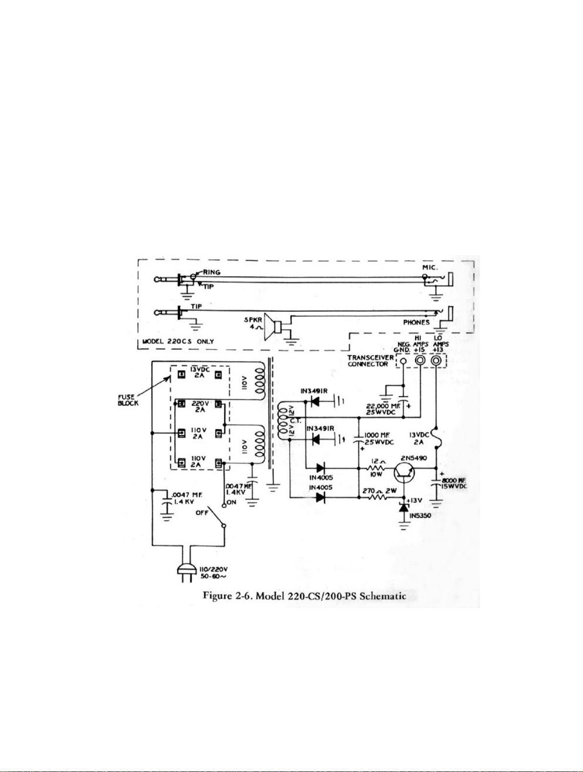
Figure 2-6. Model 220-CS/200-PS Schematic
14
Page 18

SECTION 3
OPERATION
3-1. INTRODUCTION
This section provided instructions for operating the ATLAS 210x/215x transceiver and identifies operating
contr ols, i ndica tor s, and con nectio ns. Front panel cont rols a nd in dicat ors a re sh own an d de scribe d in Fi gure 3 -1.
Rear panel controls and connections are shown and described in Figure 3-2.
3-2. CONTROLS
3-3. POWER SUPPLY ON/OFF, MOBILE OPERATION
The Function S witch has an OFF position which tu rns off the DC supply to the low current circuits. The high
current cir cuits (Driver and Power Amplifier) remain connecte d to the DC sup ply line, but are au tomatically
biased off when the low current line is turned off.
3-4. POWER SUPPLY ON/OFF, 220-CS/200PS.
The 220-CS/200-PS supplies have an ON/OFF toggle switch which turns off the AC supply line. This switch
should be used rath er tha n th e Fun ctio n S wit ch OFF p o sitio n.
3-5. FUNCTION SWITCH
The first position is the OFF position and is used for mobile operation. The REC. position places the transceiver in
receive mode. Press-to-talk and VOX circuits are operative in this position. TRANS position switches the
transceiver into transmit mode in the event a Mic. without a press-to-talk switch is used, or if you wish to hold-in
transmit mod e with out having to hold the push -t o -talk bu tt o n down. Th e CW posi ti on is also tran sm it mo de exc ept
that the Mic. Gain control now becomes a Carrier Insertion control and carrier frequency has been shifted about
800 Hertz. (S ee C W Transmission)
3-6. A. F. GAIN The A. F. GAIN control is used to control audio volume in receive
mode.
3-7. R. F. GAIN
The purpose of the R.F. Gain control is to permit decreasing the between speech noise level, thus providing more
pleasing reception. The AGC system in the ATLAS transceiver has a tremendous dynamic signal range. With full
R.F. Gain, sensitivity will automatically return to maximum in the absence of a signal, accompanied by a natural
incr ea s e i n ba ckground nois e.
You may find it annoying to hear the noise level increase every time the person being received pauses between
words or sentences. There are really only two conditions when the R.F. Gain control needs to be on full. One is
when you are scanning the band and want to hear weak as well as strong signals. But, a lot of the time you can
turn the R.F. Gain down a bit, incre as e the A.F. Gain correspondingly, and re alize more pleasing reception.
3-8. BAND SELECTOR AND TUNING DIAL, MODEL 21 Ox
The numbers on the band selector read in MegaHertz for the respective bands: 3.5 for the 80 meter band, 7.0 for
40 meters, etc.
15
Page 19

Figure 3-1. Front Panel of ATLAS 210x
Figure 3-2. Rear Panel of ATLAS 210x/215x
16
Page 20

The 0 to 500 di al scale is used on all bands. The 0 to 500 dial scale reads di rectly on the 7, 14, and 21 MHz bands.
On the 3.5 MHz band, the dial scale reading is additive . The 10 meter band is calibrated directly above the dial
scale and reads from 28.4 to 29. 4 MHz. The increment mar kings on the tuning knob skirt are 1 kHz apar t on the
lower bands, and 2 kHz apart on 10 meters.
3-9. BAND SELECTOR AND TUNING DIAL, MODEL 215x
The number on the band selector reads in MegaHertz, the same as on Model 210x, except that it has the 1.8 MHz
band instead of the 28.4 MHz.
The 0 to 500 scale reads directly in KiloHer tz on the 7, 14, and 21 MHz bands. On the 3.5 MHz bands, the di al
scale is add itive.
3-10. DIAL SET
This panel control is for adjust ing dial calibration to ex act reading at a 100 KHz mar king
3-11. CARRIER BALANCE
A trim pot is located on the PC-100C plug-in board on the right side of the transceiver. Next to the trim pot is a
capa city trimmer w hich is th e phase control . These trimmers should be adjuste d f or minimu m carrier on the low e st
frequenc y band. Connect a dummy load to the tr ansceiver, and me asure output vol tage in TRANS mode w it h MIC.
GAIN at minimum. It should null down to a leve l o f 0.10 to 0.1 5 v olt s RM S. Other bands will gi v e a fal se r ead ing
due to oscillator feedthrough which is not suppressed as much as the carrier.
3-12. S-METERZERO
This is a trim pot located on the PC-200C plug-in board. The PC-200C PC board is located under the dial drum. It
can be reached with a phillips screwdriver from the top, just behind the dial light switch. Disconnect the antenna
and adjust the trim pot for m eter 0.
3-13. CRYSTAL CALIBRATOR. The 100 kHz calibrator should be checked every 6 months or so against a
frequency standard such as WWV. Aging will cause it to gradually change frequency, especially during the first
few months. The calibrator is mounted on the back side of the aluminum partition, under the shield, behind the dial
drum. A capacitor trimmer in the upper left hand comer is for frequency adjustment. A test lead may be run from
terminal 1 of PC-100C to the antenna terminal on a general coverage receiver which is tuned to one of the WWV
frequencies: 2.5, 5,10 or 15 MHz. Adjust the trimmer for zero beat when WWV interrupts their tone modulation.
3-14. PROPER TUNING OF SINGLE SIDEBAND SIGNALS
Precise tuning of a single sideband signal is very important. Try to tune exactly to the frequency where the voice
sounds normal. Avoid the habit of tuning so the voice is pitched higher than normal, and sounds like Donald Duck.
This is an un fortu nate ha bit pra ctic ed by man y opera tor s. If you tune for an un natura l high p itch y ou will t hen b e
off frequency when you transmit. Chances are that the other station will then shift to your frequency while you are
talking, and gradually you will move up or down the band. Sooner of later one of you will accuse the other of
drifting . . . So, take the extra care to tune for a natural sounding voice, and you will then be enjoying the very best
quality in voice communications.
315. VOICE TRANSMISSION
Normal operation is with the Function Switch in the REC. position. Pressing the Mic. button switches the
transceiver into transmit mode. Or, if the VOX accessory is installed in the 220-CS console, speaking into the Mic.
will switch th e rig into tra ns mit mode. A TRANS. p ositi on is al so provid ed on t he Functi on Swit ch for lo cking i n
the transmit mo d e, or in cas e the Mi c. do e s not hav e a pre ss -to -talk sw it ch.
17
Page 21

3-16. MODULATION LEVEL
Modulatio n level is adjust ed with the Mic. Gai n control. Wh en the transceiv er is coupled into a pr oper 52 ohm
load, voice peaks will be reaching about 16 amps., although the ammeter cannot respond quickly enough to show
these peaks. Adjust Mic. Gain for average readings of 5 to 7 amps. Do not run the gain above this level, or you
will flat-to p and distort the tra nsmitted audio, a s well as cause splatt er up and down t he band. ALC will he lp
reduce this danger, but it is still possible to over-modulate, so Mic. Gain must be carefully adjusted.
3-17. ALC
The ALC control is located on the front panel of the transceiver, and is concentric with the MIC. GAIN control. It
is the inner ring with a black set screw indicating its position. ALC is the abbreviation for "Automatic Level
Control," and refers to transmitter modulation level. It aids in preventing over-modulation which causes flattoppi ng o f the po wer outpu t sta ge s, dist ort io n and sp la tt eri ng out si de t he ch ann el . Full c ount er cl ock wi se se tti ng o f
this control provides no ALC, while full clockwise setting is maximum ALC. Normally, a setting around 12
o'clock will be sati s fact or y. S o me variations between ban d s may b e not ed. By ha ving t h e ALC co ntr ol on th e fr ont
panel, you can utiliz e its advanta ge most effecti vely. To o little contr ol will make it easier to over -modulat e, whil e
too much contr ol will limit output po wer . T r y vari ous sett in g s an d a sk for signal report s unti l y ou b e com e fa miliar
with its effect. If you have a panoramic scanner, this is, of course, the best way to monitor your output signal.
318. CW TRANSMISSION
The Function Switch has a CW position which switches the transceiver into CW transmit mode. A jack on the
back is provided for insertion of a standard 1/4 inch diameter 2 conductor phone plug coming from the CW key.
Keying is accomplished by bias cutoff of the I.F. Amplifier. The keying circuit operates at less than 10 volts
positive to ground, and draws less than 5 milliamps., so any of the electronic keyers will work ok.
In CW transmit mode, the carrier frequency is automatically shifted approximately 800 Hertz. This makes it
possi bl e for one tr a n s c eiver to Q SO a no t h er t ra nscei v er on CW without having to constant ly tune the dial ba ck and
forth. On 160, 80, and 40 meters the transmit frequency is shifted lower than the receive frequency, while on 20
meters it is shifted higher. The si deband Selector switch must be in the " NORM" position for CW operation.
Send-receive changeover must be made with the Function Switch, and it may be a bit inconvenient to pass through
the TRANS position every time. The serious CW operator will want to install the semi-break-in accessory kit in
the 220-CS console. This item installs in back of the power supply, and includes a sidetone oscillator with volume,
pitch, a nd delay cont rols. Ref er to paragraph 2-18 f or alternat e s wi t c hing met h od .
In CW mode the Mic. Gain control becomes a Carrier Insertion control. With key down, advance this control
clockwise unt il the meter reads 12 amps. This will be 200 watts in put power (at nominal suppl y voltage), and
output will be about 90 wat ts. (On 10 meters the meter will re ad 8 to 9 amps., or approximately 120 watts input. )
For Novice Class operation, insert 5.5 amps of carrier for 75 watt legal power limit.
For RTTY/SSTV operation, the input should be controlled for a meter reading of 6.5 amps for 90 watts input.
Heat sink temperature is always the limiting factor on power input, and should be monitored from time to time.
Refer to par agraph 3-18.
3-19. HEAT SINK
Adequate ventilation for the heat sink is particularly important in CW operation, since average power input is
higher than in SSB transmission. Keep a check on heat sink temperature, and if it is running uncomfortably hot to
the tou c h, back do w n o n ca r r ier insertion, or ma k e t h e t r a n s missio n s horter.
18
Page 22

CAUTION
THE GREATEST DANCER TO THE POWER OUTPUT TRANSISTORS IS
OVERHEATING . THE BLAC K ANODIZED HE AT SINK IS DESI GNED TO COOL TH E
TRANSISTORS AD EQUATE LY UND ER NORMA L OPERA TING CONDI TIONS , BUT AS
WITH ANY ELE CTRO NIC O R MECH ANICAL DE VICE, I T IS U P TO TH E O PERATO R
TO MAINTAIN NORMAL CONDITIONS, AND NOT ABUSE THE EQUIPMENT.
THE MAXI MUM SA FE TEMPER ATURE OF THE HEAT SINK NEAR THE OUT PUT
TRANSISTORS IS ABOUT 150 DEC. F. THIS IS A TE MPERATURE THAT WI LL BE
TOO HOT FOR YOUR FINGERS TO HOLD, SO A GOOD TEST IS TO PUT YOUR
FINGERS ON THE FINS CLOSEST TO THE T RANSISTORS. I F YOU CAN HOLD ON
WITHOUT A LOT OF DISCOMFORT, YOU'RE OK.
OVERHEATING MAY BE CAUSED BY: (A) MODULATING TOO HEAVILY, (B)
MAKING LENGTHY TRANSMISSIONS WITH SHORT RECEIVING PERIODS, OR (C)
RESTRICTION OF AIR CIRCULATION AROUND THE HEAT SINK. IF THE AIR
TEMPERATURE IS HIGH, SUCH AS ON A HOT DA Y, OR IN A HOT PARKED CAR,
COOLING CAPACITY WILL BE REDUCED. A GOOD RULE IS TO CHECK THE HEAT
SINK FROM TIME TO TIME, AND MAKE CERTAIN YOU'RE NOT RUNNING TOO
HOT. BACK OFF ON MODULATION LEVEL, OR SHORTEN TRANSMISSION TIME.
UNDER ABNORMAL CONDITIONS, A SMALL FAN MAY BE DIRECTED AT THE
HEAT SIN K. THIS IS A N EXCELLENT IDEA I F SSTV OR RTTY TRA NSMISSION IS
CONTEMPLATED.
19
Page 23

SECTION 4 CIRCUIT THEORY
4-1. INTRODUCTION
The Atlas transceiver employs several unique features in its circuit design which lead to exceptional performance.
Most of the circuitry is directly descended from similar equipment manufactured for military and commercial
markets by Southcom International, Inc., of Escondido, California. Les Earnshaw, ex ZL1AAX is President and
Director of R&D of this company. Operating under license from Southcom, Atlas Radio has access to the very
latest state-of-the-art circuit designs which have been tested, proved, and type accepted for military and
commer ical use. Figure 4-1 illustrates the modular desig n and plug-in P.C . boards of the Atlas transceivers.
4.2. RECEIVER I N P UT CIRC UI T.
Referring to the block diagram illustrated in Figure 4-2, notice that there is no preamplification of the signal. After
passing through input tuning circuits, the signal is coupled directly into a double balanced diode ring mixer where
it is heterodyned to the 5520 kHz I.F. . Thus, the overload and cross modulation problems commonly encountered
with an R.F. Amplifier stage are largely eliminated. This has always been somewhat of a problem with vacuum
tube R.F. Amplifiers, and a much more serious problem with transistor or F.E.T. Amplifiers. With its advanced
front end design the Atlas transc eiver will continu e receiving signals in the presence of extremely strong adja cent
chan ne l station s t ha t w ould overload, cross modu l a te, or des e n sitize other
receivers.
4-3. SENSITIVITY
As with most new developments in technology, it may be difficult to accept the fact that a proper receiver can
exhibi t goo d sen sitivit y wit hou t a stag e, or mor e, o f R.F. a mpli ficati on pri or to frequ ency c onv ersion . The fact i s
that the Atlas is at least as sensitive as the best of the tube or solid state receivers having R.F. Amplifiers. This is
due largely to the very low noise figure of the double balanced diode ring mixer, followed by a low noise I.F.
Amplifier. Sensitivity is rated at 0.3 microvolts for a signal-plus-noise to noise ratio of 10 dB. Typical
measurements will read 0.15 to 0.2 microvolts.
4-4. SELECTIVITY
Following the low noise first I.F. Amplifier, the signal passes through the crystal ladder filter, a highly
sophisticated package designed especially for the Atlas transceiver by Network Sciences, Inc., of Phoenix,
Arizo na . Her e is w her e su per ior se lect i vit y ha s be en ta il or ed to ta ke full ad vant a ge o f th e extr em el y wid e ra nge of
signal levels that the front end design is capable of handling. A 6 dB bandwidth of 2700 Hertz was carefully
selected to provide audio response from 300 to 3000 Hertz in both receive and transmit modes. While occupying
slightly more bandwidth than a 1200 or 2400 Hertz filter, it has been convincingly proven that transmission and
reception of the audio frequencies between 2400 and 3000 Hertz provides a substantial improvement in weak
signal readabilty. At the same tune, the improved fidelity of voice communications is readily noticeable, and helps
account for the report of "broadcast quality" from the Atlas. The 6 db bandwidth of 2700 Hertz is backed up by a 6
to 60 db bandwidth ratio of only 1.6 (shape factor), and ultimate rejection greater than 130 dh. It is this extremely
steep skirt selectivity, illustrated in Figure 4-3, which will reject strong adjacent channel signals.
45. OSCILLATOR SWITCHING
The unique method of changing from receive to transmi t mode by switching the carrier oscillator an d VFO is
illustrated i n the block diagra m, Figure 4-2. Thi s new development i s responsible for gr eat simplificati on of the
transceiver circuit, leading to fewer c o mpo nent s , lo wer c o st, and grea t r ealiability.
20
Page 24

21
Page 25

Page 26

Figure 4-3. Crystal Ladder Filter Selectivity Characteristics
23
Page 27

In receive mode the first mixer heterodyne s the antenna sig nal with VFO inject ion. In transmit mode the first
mixer functi ons as a bala nced modula tor wit h carrier o scillator inj ection and Mic. amp. in put. In bot h modes th e
first mixer output is at the in termediate frequency (I.F.) of 5520 kH z.
In receive mode the second mixer functions as a product detector with carrier oscillator injection. Its output
couples audio frequencies to the receiver audio system. In transmit mode the second mixer heterodynes the I.F.
signal with VFO injectio n. Its output is now at the tran smit freque ncy, and is coupled through tuned circuit s to
pream pl ifier s, dr iver stage, an d po w er ou tput amp l ifier.
Oscillator swit chi ng is acco mpli s h ed wit h four F.E .T.'s, resultin g in ver y low inter c ou p lin g bet we en os cilla t ors.
4-6. TRANSMITTER BROADBAND CIRCUITRY
The amplifier stages of the transmitter provide full power output over the 1.8 to 21.4 MHz range, about 60%
power a t 29.7 MH z, and r equire no tu ning. T uned cir cuits bet ween the second m ixer and t ransmit ter ampl ifier
module select the desired mixer product and reject the unwanted products. These tuned circuits are band switched
and pr ovi de full c over a ge o f ea c h ba n d. T hey ar e d oubl e tuned a nd o v er co u pled, r equ iri n g no furt h er a dju st me nt
after being factory set.
Harm onic outpu t from the Power Amp lifier is su ppress ed by a band switched t wo secti on low pass f ilter. Thi s
filter is connected between the Power Amplifier output and antenna terminal. The low pass filters and Power
Amplifier are both designed for a 50 ohm load. It is important that the load be quite close to 50 ohms, nonreactive, in order to operate at full rated powe r.
4-7. RECEIVER BROADBAND CIRCUITRY
The receiver in put filter s are ba nd switched, a nd provide ful l band cover age without n eed for a panel pea king
control. In addition, the signal passes through the low pass transmitter filter, suppressing possible interference
from str ong loca l VHF signal s .
4-8. ALIGNMENT AND TROUBLESHOOTING
The overall chassis schematic diagram is Figure 4-15, and is placed at the end of this section to facilitate the
techni cian i n matchi ng the P. C. boar d schema tics t o the o verall schemat ic. T he indivi dual P. C. boar d schema tic
diagra ms ar c sho wn in Fi gure s 4-4 t hrou gh 4-1 4. Vol tage measu rem ent s and pa rts li st are l ocat ed adja cen t to t he
P.C. board sc hematics.
4-9. VOLTAGE CHARTS
All voltage measurements must be made with a meter having at least 10 megohms input resistance. All D.C.
voltages are designated by the + (positive) symbol. Voltage figures not having the + symbol are RMS values of an
AC voltage. Refer to the following notes when making any voltage measurements.
NOTES
1. RMS voltage measured with R.F. probe, and bandswitch in 7
MHz position.
2. Approximate RMS voltage with Mic. Jack input of .03
volts at 1000 Hz. Mic. Gain at maximum clockwise.
3. RMS vol tage with R.F. probe, CW mode, Mic. Gain at
Maxi mum clo ckwise .
4. Full R. F. Gain, no sign al input.
24
Page 28

4-10. SIGNAL FREQUENCY RANGES AND
1.8*
3.5
7
14
1.8*
3.5
7
5,200
LOCAL OSCILLATOR FREQUENCIES
Atlas Ra dio, Models 210x and 215x:
(a) Normal
Frequency ranges
with internal VFO
(a) Normal frequency rang es with internal VF O ranges with internal VFO.
Band, MHz Low Frequ ency Limit,
21
28.4*
• 1.8 MHz band, model 21 5 x onl y. 28.4 MHz band, model
210x onl y.
Band. MHz Operating Range,
1.8*
3.5
7.0
14
21
28.4*
*1.8 MHz b and, model 21 5 x onl y. 28 .4 MHz band, m odel
210x onl y.
KHz. .or
1,750
3,300
6,900
13,800
20,800
27,800
KHz
1,80 0- 2,100
3,50 0- 4,000
7,00 0- 7,500
14,000- 14 , 5 00
21,000-21,500
28,400 - 29,400
High Frequency Limit,
KHz
2,150
4,150
7,700
14,700
21,700
30,000
VFO Injectio n
Frequency, KHz
7,320- 7,620
9,02 0- 9,520
12,520- 13,020
8,48 0 - 8,980
15,480- 15 , 9 80
22,880 - 23,880
(b) Extended frequency limits by adjustment of VFO trimmers.
VFO trimmers are reached by removing the transceiver top cover. Adjustment of a trimmer for lower or higher
frequency will move the entire band down or up, and will came the dial Male to read less accurately. Special
frequency ranges with accurate dial calibration are available from Atlas on special order.
Band, MHz Frequency Range, KH z , wi th C r ystal Oscill ator
1,700- 3,000
3,000-
5,800- 10,000
14
21
*1.8 MHz b and, model 21 5 x onl y.
Note: The Model 10x will not operate on the 28.0 MHz band. (c) Extended frequency ranges when using Model 10x
external crystal oscillator accessory.
13,800- 14,900
20,600-21,600
25
Page 29

4-11. PC-100C - FIRST MIXER/FIRST I.F. AMPLIFIER
In the receive mode, the R.F. signal is coupled from terminal 1 of PC-100C to the primary of the trifllar toroid
transformer LI 01, through capacitors C101 and C110, to the double balanced diode ring mixer, D101 through
D104. The VFO oscillator signa l is coupled throu gh R105 — C109 to the center tap of the secon dary windi ngs of
L101, then through C101 and C110 to the First Mixer. The two signals are heterodyned and the difference
frequency is the 5520 kHz I.F. signal. The output of the First Mixer is coupled through the trifllar toroid
transformer L102, through a tuned circuit consisting of C104 through Cl 07 and LI 03, to the base of the First I.F.
Amplifier Q101. The tuned circuit is tuned to the L.F. frequency of 5520 kHz. The signal is amplified by Q101
and then connected through terminal 13 of PC-100C to the crystal ladder filter, which then goes to terminal 3 at
PC-200C.
In the transmit mo de, the tran smit audio inpu t is coupled from terminal 7 of PC-100C thr ough LI 04 to th e First
Mixer, whi ch no w op erates a s a ba lan ced mo dulator . Th e carri er o scilla tor injecti on i s throu gh ter minal 4 o f PC100C and is coupled to the balanced modulator through R105, C109, C110, and C101. The output of the balanced
modulator (D101 through D104) is a double sideband, suppressed carrier signal. R101 is used to balance out the
carrier, and C103 is used for phase balance. The double sideband signal is at the I.F. frequency of 5520 kHz, and
is tuned by the tuned circuit consisting of C104 through C107 and L103. Q101 is the Transmit I.F. Amplifier, and
its output is coupled to the Crystal Ladder Filter in the same manner as in the receive mode.
Diode D105 is used to short the receiver input circuit in transmit mode, thus preventing stray transmitter energy
from entering the mixer circuit. Diodes D106, 107 and 108 permit R.F. Gain control of Q101 during Receive
mode, while maintaining fixed gain in Transmit mode. RL101 switches the +13 volt line for Transmit mode, and
also switche s the met er cir cui t fr o m receiv e to tra n smit fu n cti on .
One of the primary a dvanta ges of t he doubl e balance d diod e ring mixer i s that b oth signal a nd oscillat or i njecti on
frequenci es are essentially balanced ou t and do not appear in the output circuit. Only the sum and di fference
frequencies are present at the output. Also, the oscillator is balanced out from the antenna input terminal,
eliminating the risk of o scillator radiation.
PC-100C CIRCUIT COMPONENTS
First Mixer, First I.F. Amp
C101,108,109,110,112
C102 ..............
C 103 Car. Phase Bal.. .
C104,107 ..........
C105 ..............
C106 ..............
C111 ..............
C113 ..............
D101,102,103,
104,107,108 . . .
D105,106 ..........
Q101 ..............
. . . . .01 MF 100VDisc
....... 22pF10% Disc
. . . . 10-80 pF Trimmer
. . . . .001 MF 20% Disc
. . . . . 100 pF 10% D isc
....... 91 pF 5% Disc
..... 0.1 MF 50V Disc
15 MF 20V Electrolytic
. 1 N4148 Silicon Diode
. . BA-182 Silicon Diode
. . 2N3866 1st I.F. Amp.
R101 ......
R102.......
R103,110. ..
R104 ......
R105 ......
R106,107 ...
R108 ......
R109 ......
RL101......
L101.102. ..
L103 ......
L104,105 .
26
. . . Car. Bal. Trim Pot. 100 Ohms
............ 10K 10% 1/4Watt
........... 4.7K 10% 1/4Watt
............ 330 10% 1/4Watt
............. 47 10% '/4Watt
............. 1K 10% 1/4Watt
............ 180 10% 1/4Watt
............ 820 10% 1/4Watt
............ 3p2t 12 vdc Relay
......... Trifilar Toroid XFMR
............. Shielded I.F. Coil
................ 200 uH RFC
Page 30

PC-100C VOLTAGE CHART
NUMBER
3 Gnd. Gnd. 4 0.6(11 1.15(1) 6 Gnd. Gnd. 7 0 0.33 (2)
8
Gnd. Gnd.
11 +13 +13
13 +11.8 +10.2 14 +7.3 (4)
+8.5 (4)
15
+3.0 +3.0 16 +3.0 +3.0
+3
20 +13 • 21 +3 +13 22 • +12.6
I.F. Amp.
Collector
+12.216)
+9.4
TER M STRIP
1
9
REC. TRANS.
(0)
(0)
N.C. N.C.
TER M. STRI P
NUMBER
10
REC. TRANS.
+13 +13
TER M. STRI P
NUMBER
19
REC. TRAMS.
+12.6
18
+13 +12.6
Emitter
+3.4 (6) +4.4
27
Page 31

4-12. PC-200C Second I.F. Amplifier, Second Mixer, Mic. Amp.,
S-Meter Amp.
In receive mode, the I.F. signal from the 8 pole Crystal Ladder Filter is coupled through terminal 3 of PC-200C to the
Integrated Circuit Q201, which is the Second I.F. Amplifier. The signal is amplified and coupled through the tuned
circuit that consists of R203, C205 and L201, which is tuned to the I.F. frequency of 5520 kHz; through R204 to the
Trifilar Toroid Transformer L202, to the input of the double balanced diode ring Second Mixer Stage consisting of
D201 through D204. In the receive mode, this mixer acts as a product detector by hetrodyning the carrier oscillator
injection and I.F. input to the audio output frequency. The audio output is coupled through C206 and the Trifilar Toriod
Transformer L203, through the RF choke L204 to terminal 5 of PC-200C. From terminal 5, the audio signal is coupled
direct to terminal 20 of PC-300C.
In transmit mode, the double sideba nd signal fro m PC-100 C is passed throu gh the Crystal Ladd er Filter whic h removes
the unwa nted si deband . The re sultant single si deband s ignal is coupled through terminal 3 of PC-200C to the Second
Mixer in the same manner as in the receive mode. The VFO injection frequency is through terminal 7 of PC-200C
through C208 to the center tap of the Trifilar Toroid Transformer L203. The heterodyning action of the Second Mixer
produces the RF transmit frequ e ncy which is co upled through the pr imary wi n ding of L203 to terminal 9 of P C-200C.
Q202, which is an integrated Circuit, act s as a 3 stage Mic. Amplifier and also the S-Metcr Amplifier.
Second I.F. Amp., Second Mixer, Mic Amp. S-Meter Amp.
PC 200C CIRCUIT COMPONENTS
C201,202,203,206,
207,208,211. ....... .01 MF l00VDi s c
C204 ................... 100 MF 20VDisc
C205. .................... 130pF5% SM
C209.220. ............... 0.1 MF 50V Disc
C210. ............. 6.8 MF 35V Electrolytic
C212,218 .......... 2.2 MF 50V Electrolytic
C213,215,219 .............. .001 20% Disc
C214.............. 15 MF 25V Electrolytic
C216.217. .......... 22 MF 16V Electrolytic
C221. ............... .0022 MF 10% Mylar
D201,202,203,
204,206,207. .... 1 N4148 Silicon Dio de
D205............. 1N4740 10V Z e ner Diode
L201 ................. Shielded I.F. XFMR
L202,203 ............ Trifilar Toroid XFMR
L204....................... 200 uH RFC
L205 .................... 0.6 uH I.F. Trap
Q201 ..................... MC1350PI.C.
Q202 ...................... CA3086I.C.
R201 ................... 180 10% '/4 Watt
R202.210. .............. 2.2K 10% 1/4Watt
R203 .................. 3.9K 10% '/4 Watt
R204.205. ................ 47 10% 1/4 Watt
R206.213,221 ............ 470 10% '/4 Watt
R207,212. .............. 5.6K 10% '/4 Watt
R208 .................... 68 10% 1/4 Watt
R209.217 ................ 1K 10% '/4Watt
R211 ................... 27K 10% '/4 Watt
R214. ................. 150K 10% 1/4 Watt
R215 .................. 100K 10% '/4 Watt
R216.219 ............... 10K 10% 1/4 Watt
R218. .................. 39K 10% 1/4 Watt
R220 ................... 100 10% 1/4 Watt
R222. ............... 1K S-Meter Trim Pot.
--
28
Page 32

PC-200C VOLTAGE CHART
1
2
3
4
5 • • 6
9 0
10
11 0
12
13 •
14 • +6 15
NUMBER
16 9
17 0 0 18
19
20
21
22
4
5
6
NUMBER
•
•
•
6 •
7 e
8 0
9
10
11
12 e
14 •
TER M. STRI P
NUMBER
7
8
REC. TRANS.
+13
Gnd. Gnd.
+3.6
Gnd. Gnd. -
Gnd. Gnd.
0.5511) 0.53 (1)
Gnd. Gnd.
Gnd. Gnd.
Gnd. Gnd.
Gnd. Gnd.
+13
+3.3
0.27 (3)
0.05 (21)
0.33 (21
TER M. STRI P
Q201,I.C.
I.F.Amp.
Term. 1-2-8 +10.4 +10.1
3-7
REC. TRANS.
0.06 12)
Gnd. Gnd.
+3.5 +3.5
+2.6 +2.6
+10 +10
+2.6 +2.6
Gnd. Gnd.
+0.39 +0.37
+0.45 +0.43
+0.38 +0.36
TER M. STRI P
Q202, I.C.
Mic. Amp.
Term. 1-5
2-4-14
3
REC. TRANS.
+5.3
+4.2
+3.5
+2.1
+1.5
+5.3
+3.4 +3.4
+2.7 +2.7
+9.8 +9.8
+0.95
+0.25
Page 33

4-13. P C -300C Receiver Audio, Os cillator S witch
The audio output from PC-200C is coupled through terminal 20 of PC-300C, through C303 to pin 12 of the Integrated Circuit
Q301, which is the A.F. Amplifier. The output of Q301 is coupled through C302 to terminal 22 of PC-300C to the AF GAIN
control on the front panel, then back through terminal 12 of PC-300C to the input of the AF Power Amplifier Q302. The
signal is further amplified and coupled through C320 to terminal 15 of PC-300C to the speaker. Q302 delivers 2 watts of
audio to th e 3.2 ohm speaker .
The output of Q301 is also coupled through C309 to D301 and D302, the AGC rectifiers. AGC is then coupled through L301
to the input of Q301B which is the AGC Amplifier. The AGC output is fed from pin 7 of Q301B through terminal 17 of PC300C to terminal 19 of PC-200C where it is coupled through R202 to the Second I.F. Amplifier. AGC attack and decay time
are controlled by C310, R 312, and R311.
ALC voltage fro m th e SW R br idg e i s coup led t hrou gh D3 03 to Q3 0 1 B, con trol ling I. F. gain sim ila r t o AG C in r ec eive mode .
This same circuit also carries the high SWR, or infinite SWR protection system. High values of reflected voltage from the
SWR bridge will reduce I.F. gain, resul ting in reduced transmi tter drive. SWR figure of 6 or more will practicall y cutoff the
transmitter drive through this circuit.
Q303, 304, 305 and 306 are the F.E.T. Oscillator switches, which connect the VFO and Carrier Oscillator (BFO) to t he t wo
mixer stage s in pr o per r elationship for r ec ei ve a n d tra n s mit functions. Th e swi tchi n g i s c on tro ll ed b y t h e "T" line on terminal
1, which is grounded in receiv e mode and goes +13 in transmit mode.
PC-300C CIRCUIT COMPONENTS
Receiver Audio, Os ci llator S w i tch
C301,304,307,308,314, L301 .....................………………………... 33uHRFC
323,324,325,326. .. …………………... .01 100V Disc
C302,317. ..............………………… .1 MF 50V Disc
C303 .................. ………………….22 MF 100V Disc
C305. ..........……………….. 47 MF 6.3V Electrolytic
C306.319. .......……………... 15 MF 20V Electrolytic
C309.310.321. ....…………. 2.2 MF 50V Electrolytic
C311,315. ........……………. 47 MF 16V Electrolytic
C312. ..........………………. 6.8 MF 35V Electrolytic
C313 ............………………. 75 MF 15V Electrolytic
C318 ...........……………….. 22 MF 16V Electrolytic
C320 ...........……………… 250 MF 20V Electrolytic
C322 ...............…………………. 47 MF 100V Mylar
C327 ................…………………... 5-30 pF Trimmer
0301,302,303, 0303,304,
304,305,306 ...………………. 1N4148 Silicon Diode
D307.308 .........……………... BA-182 Silicon Diode
R301.307.313 ........………………. 5.6K 10% '/4 Watt
R302 ................…………………... 27K 10% 1/4 Watt
R303.310,311,324,
321,327,328 .......…………………… 1K 10% '/4 Watt
R305,315,316 ........………………... 470 10% '/4 Watt
R306.314 ...........…………………. 100K 10% '/. Watt
R308 ...............………………….... 1.5K 10% '/4 Watt
R309,317,318. ........……………... 2.2K 10% 1/4 Watt
R312 ...............……………………... 1M 10% '/4Watt
R319,320,3 22,323,325,326. ……..6.8K 10% 1/4 Wat t
Q301A .............………………….. CA3086 A.F. Amp.
Q301B. .............………………… CA3086 AGC Amp.
Q302. ............…………………. LM380N A.F. Output
305,306 . 2N3819 FET Oscillator Switch
30
Page 34

TER M. STRI P
2
5
7
10
12 0 0 13
0
20
22 0 0
—
—
— 6
— 7
— 8
— 12
— 13
— 14
—
+7
0
14
NUMBER
1
3
4
6
8
9
11
14
15
16
17
18
19
21
REC.
Gnd.
+13
Gnd.
.0.58(11) 1.18(1))
Gnd.
.0.58(11) 1.22(1)
Gnd.
.55(1)
Gnd.
.58111
Gnd.
+13
Gnd.
2VAC Max.
Gnd.
+4.2
+10
0
Gnd.
TRANS.
+13
+13
Gnd.
Gnd.
Gnd.
.0.53(1))
Gnd
.0.55(1)
Gnd.
0
Gnd.
0
Gnd.
+4.2
Varies.ALC
+10
0
Gnd
PC-300C VOLTAGE CHART
TER M. STRI P
NUMBER
Q301. I.C.
A.F. Amp.
Term. 1-5
2-4
3
Q302. I.C.
A.F. Amp.
Term. 1
2-3-4-5-7 9-1011-
12-13
6
8
REC.
+6.7
+2.2
+1.5
+4.2
+3.5
+9.8
+1.9
+1.2
+12
All Grounded
+5.2
+13
TRANS.
+0.6
+1.8
+13
TER M. STRI P
NUMBER
Q303
Gate
Source
Drain
Q304
Gale
Source
Drain
Q305
Gate
Source
Drain
Q306
Gate
Source
Drain
REC.
+0.7 +9
+8.8 +8
+8.8
+9.8
+8.8
+8.8 +8
+94
+8.8 +8
+8.8
+0.7 +9
+8.8
+8.8 +8
TRAMS.
+8
•
+8
•
+8
+8
(1)
NOTE: RMS voltage measured with R. F. probe, and bandswitch in 7 MHz position.
Page 35

4-14. PC-500D/520A Pre-Amplifier, Driver, Power Amplifier, SWR Protect
Interstage Transformer
2 Watt
The R.F. output from PC-200C is coupled through the Transmitter Input Tuning circuit (PC-900) to the input
connection on PC-520A. From the input connection, the signal is coupled through C504 to the base of the PreAmplifier Q501, where it is amplified and coupled through C501 to the base of Q502 for further amplification.
From Q502, the signal is coupled through the Toriod interstage transformer T501 to the base of the Driver Q503
on PC-500D. The output of the Driver is coupled through the Ferrite Core Driver Transformer T502 to the base
inputs of Q504 and Q505, which are the Power Amplifiers. The outputs to the Power Amplifiers are coupled
through the Ferrite Core Output Transformer T503 to the output connection on PC-500D. From this connection,
the output signal passes through relay RL1, through the Low Pass Filters PC-100/1020 to the 50 ohm antenna
connector.
Q506 is a bias regulator for the output stage. Trim pot R515 is used to adjust resting current collector to
approximately 1/2 amp. Diodes D501 and 502 regulate the bias circuit, and are thermally connected to the heat
sink in order to sense temperature increase. Thus, bias voltage automatically increases with temperature,
preventing thermal runaway of the output transistors.
Reflected voltage which is generated by a mismatch in the antenna system is rectified by D1102 and D1103 on
PC-11 00 A in a dou bler circu it, filter ed, and th en c onne cted t o Q50 7, t he SWR pr ote ct cir cuit . Ther e it i s use d to
reduce the gain of the first pre-amplifier, thus reducing drive to the power output amplifier. The trimpot R522 is
adjusted so that Standing Wave Ratios greater than 2 to 2.5 will drastically reduce R.F. drive.
PC-500D/520A CIRCUIT COMPONENTS
Pre-Amplifier, Driver, Power Amplifier, SWR Protect
C501,502,504,507,510,518,
519,520,521. ....... .01 MF l00VDisc
C503.509................ 0. 1 MF 5 0V Disc
C505 ................. 37-250 pFTrimmer
0506,512,517.......... 0.1 MF100V Mylar
C508 ,516,522 ...... 15MF 100V Electrolytic
C511.............. 2.2 MF 50V Electrolytic
C513.514 ........... 330pF5% Silver Mica
C515....... .... .... 10 0 pF 5% Silve r Mi ca T501 ... .... .. T oroid
T502. ....... Ferrite C ore Dri ve r Trans f ormer
T503 ....... Ferrite Core Output Transformer
L501 ........................ 33uHRFC
L502 ....................... 1.4uHRFC
L503 ....................... 0.6 uH RFC
L504. ................ 3 Ferrite Beads, RFC
L505 .......... 1.5 uH RFC and Meter Shunt
L506 ................. 7.6 uH Toroid, RFC
D501,502,503 ........ SI-05 Regulator Diode
R501 .......... ........ 2.7K 10% '/4 Watt
R502 .......... .......... 10 10% 1/4 Watt
R503.514. ..... .......... 470 10% 1/4 Watt
R504, 513. ............... 180 10% '/4Watt
R505,506. ................ 47 10% % Watt
R507.508............... 1.5K 10% 1/4 Watt
R509 .......... ... ...... 270 10% '/4 Watt
R510 .......... ... ...... 470 10% % Watt
R512, 519 ................ 1.1 10% 1/4 Watt
R515 ..................... 1K Bias Adjust
R516 ................... 560 10% % Watt R517 .................... 1010%
R518, 520 ................ 4.7 10% 1/4 Watt
R521 .......... ... ...... 220 10% '/4Watt
R522 ..................... 2.5K Trim Pot
R523.R524 ............... 1K 10% 1/4 Watt
Q501 ................. MPS6514Pre-Amp
Q502 .................. 2N3866 Amplifier
Q503.................. RCA 40582 Driver
Q504.505 CTCCD2545 Power Amplifier
Q506 .............. 2N5490 Bias Regulator
Q507 .......................... 2N3646
Page 36

TERM. STRIP
NUMBER
Q501
Base
+3.5 Collector
+10.2 Emitter
+2.8
Q502
Base
+2.4
Collector
+12.6
Q503
Base • +1.3 Collector
+15 +13 Emitter
•
+.1
Q604, Q506
Base
+.4
+.7
Collector
+16 +13
• •
Emitter
REC. TRANS.
0
0
0
0
0
+1.5
0
PC-500D VOLTAGE CHART
TERM. STRIP
NUMBER
Emitter
REC.
TRANS.
TERM. STRIP
NUMBER
Q606
Base
Collector
Emitter
REC.
•
•
+.03
TRANS.
+1.2
+13
+.7
Page 37

4-15. PC-400C VFO Circuit Board and Tuning Circuits
407, 408 .......... .01 MF l00v Disc R402, 403 ......
.... 10K 10% 1/4 Watt
C403 ................ 300pF 5% SM R404, 409 ......
.... .470 10% 1/4 Watt
C404 ................ 430pF 5% SM R405 .........
.... .680 10% 1/4 Watt
C405 ............... l00pF 10% Disc R406 ..... ....
.... 15K 10% 1/4 Watt
C409 ............. .001 MF 20% Disc R407 .........
.... 4.7K 10% 1/4 Watt
C410 ................ 15pF 5% Disc R408 .........
.... .820 10% 1/4 Watt
L402.................. 1uh RFC R410 .........
.... 2.7K 10% 1/4 Watt
L403.................. 33 uh RFC R411.........
..... 10 10% 1/4 Watt
Q401 .............. 2N706 Osc. St age R413 .........
..... 100 10% 1/4 Watt
Q402 .............. M PS6514 Buffer
C412,413,414 ......... l0pF 10% Disc
C429.........
....... 15pF 5% Disc
C415,420,421,447 ...... 4.7pF 10% Disc
C430, 438, 439 ...
....... 22pF 5% Disc
C417 ................ 22pF 5% Disc
C431,434,4 35 . . .
...... 4.7pF 10% Disc
C418.424 ............. 20pF 5% Disc
C432,437,442,443
...... 10pF 10% Disc
C425 ................ 27pF 5% Disc
C444.........
....... 0.8pF Dial Set
C426 ................ 0.8pF Dial Set
C445A ........
..... 4pF Main Tuning
C427A .......... ... 4pF Main Tuning
C445B ........
..... 8pF Main Tuning
TERM. STRIP
Emitter
+3.5
+3.5
TERM. STRIP
Collector
+9.2
+9.2
TERM. STRIP
PC-400C co ntai n s th e VFO Oscillator Q401, F.E.T. Buffer 0402, and Output Amplifier 0403. The output of the VFO
Oscillator is coupled through C408 to pin 3 of the exte rnal oscillato r socket, through th e jumper to pin 2, then direct to
termin al 13 of PC-300C. From terminal 13 of PC-300C, the VFO signal is fed to the F.E.T. Oscillator Switch. Voltage
regu latio n for the VFO circuits is prov ided by Ql and D2 on the main chassis.
VFO FREQUENCY CHART, MODEL 210x
I.F. at 5520 kHz
SIGNAL RANGE
3500- 4000
7000- 7500
14000- 14500
21000-21500
28400 - 29400
INTERNAL VFO
RANGE
9020- 9520
12520- 13020
8480- 8980
15480- 15980
22880 - 23880
VFO FREQUENCY CHART, MODEL 215x
I.F. at 5520 kHz
SIGNAL RANGE
1800- 2100
3500- 4000
7000- 7500
14000- 14500
21000-21500
INTERNAL VFO
RANGE
7320- 7620
9020- 9520
12520- 13020
8480- 8980
15480- 15980
PC-400C CIRCUIT COMPONENTS
C401, 402, 406, R401, 412 ......
Q403 . .......... 2N3866 Outp ut Amp.
MODEL 21 Ox TUNING SECTION
C411, 416, 419, 422, 423 . . 3-12pF Trimmer
C427B ............. 8pF Main Tuning
PC400C VOLTAGE CHART
NUMBER
0401
Base
Collector
REC. TRANS.
+4
+4
+4.5
+4.5
NUMBER
Q402
Base
Emitter
MODEL215x
C428, 433,43 6,440
C446.........
REC. TRANS.
+5.2
+5.2
+6
+6
..... 27 10% 1/4 Watt
TUNING SECTION
, 441 . . 3-12pF Trimmer
....... 27pF 5% Disc
NUMBER
Q403
Base
Collector
Emitter
REC. TRANS.
+4.3
+6
+3.6
+4.3
+6
+3.6
34
Page 38

Page 39

4-16. PC 600 Carrier Oscillator, Buffer Amplifier
PC-600 consists of those components necessary to generate the normal carrier frequency of 5520 kHz, and the
opposite sideband frequency of 5523.3 kHz. Crystal X602 is the Normal sideband crystal, and X601 is the
opposite sideband crystal. Q601 is the Carrier Oscillator, and Q602 the Buffer Amplifier. The output of the Buffer
Amplifier is coupled through C612 to terminal 6 of PC-300C. From terminal 6, on PC-300C, the carrier frequency
is fed direct to the F.E.T. Oscillator Switch.
PC-600 CIRCUIT COMPONENTS
Carri er Oscillator Bu ffe r Amplifier
C601 .......... ... ....... 22 pF 10% Disc
C602.603. ............... 5-30 pF T ri mme r
C604 .................... 10pF 10% Disc
C605 ,606.607,611.612 .... .01 MF 100V Disc
C608............... 200 pF 5% Silver Mica
C609. .............. 100pF5% Silver Mica
C610 .......... ... ....... 15 pF 10% Disc
C613 .......... ... ....... 510pF5%Di sc
D601 ................ BA-182 Silicon Diode
D602 ............... 1N4148 Silicon Diode
Q601,602 ............... 2N706 Transistor
R601 .......... ........ 4.7K 10% 1/4 Watt
R602.604 ............... 15K 10% '/4 Watt
R603.613 ...... .......... 1K 10% '/4 Watt
R605 .......... ... ...... 220 10% % Watt
R606 .......... ......... 22K 10% '/4 Watt
R607 .......... ......... 10K 10% '/4 Watt
R608.611. ..... ........... 82 10% '/4 Watt
R609,610 ...... ......... 33K 10% % Watt
R612 .......... ... ...... 470 10% % Watt
L601 .................... 1.4 uH inductor
X601 ........... .. 55 23.3 Khz OPP. SB Xt al
X602 ............. 5520 Khz Norm. SB Xtal
36
Page 40

Page 41

4-17. PC-800C/1200 Receiver Input Tuning
PC-800C contains those components necessary for receiver input tuning. The transformers
are bandswitched and provide for full coverage of each band. The transformers have iron
cores th at are fa ctory ad juste d, and sh ould not r equir e furth er tunin g. The cou pling ca pacitors in each transformer are selected to give the amount of overcoupling required for full
band coverage, and eliminate the need for a front panel peaking control.
MODEL 210x PC-810C/1200 CIRCUIT COMPONENTS
Receiver Input Tuning
C801 ................... 240 pF 10% Disc
Q802,803 ............. 1800 pF 10% Myl a r
C804 ................... 120pF 10% Disc
C805.806. ............... 820 pF 10% Disc
C807 .................... l0pF 10% Disc
Q808,809,810,811. .......... 91 pF5% Disc
C812,813. ................ 47 pF 10% Disc
C814. .................... 180 pF5% SM
Q1201,1202 .......... .0022 MF 10% Mylar
C1203.1210 ............... 470pF5% SM
C1211 .................... 200 pF5% SM
L801 .................... 7.2 uH Toroid
L802 803 ................. 1.25 uH Toroid
L804 ..................... 3.6 uH Toroid
L805 806 .................. .65 uH Toroid
L807 808 ................. 1.4 uH Tuned
L809.810.811.812 ........... .65 uH Tuned
L1201.1202 ......... .6 uH Tuned 5520 Khz
L1203 .............. .6uHTuned 11.8Mhz
L1204 ........................ 11.8Mhz
L1210 ........................ 17.8 MHz
MODEL 215x PC-810C/1200 CIRCUIT COMPONENTS
Receiver Input Tuning
C815 ..................... 360 pF5% SM
C816.817 ............. 3300 pF 10% Myla r
C818 ................... 240 pF 10% Disc
C819.820 ............. 1800 pF 10% Myla r
C821 ................... 120 pF 10% Disc
C822,823. ............... 820 pF 10% Disc
C824 .................... 10 pF 10% Disc
C825,826,827,828. .......... 91 pF 5% Disc
C829 ..................... 180 pF 5% SM
C 1205,1206, 1207. ..... .0022 MF 10% Mylar
C1208.1209 ............... 470pF5% SM
L813 .................... 16.5 uH RFC
L814.815. ................... 1.7uHRFC
L816 . .............. 7.2 uH Toroid
L817, 818 ................ 1.25 uH Toroid
L819 ............... 3.6 uH Toroid
L820 821 ............... .62 uH Toroid
L822 823 ................ 1.4 uH Tuned
L824 825 ................ .65 uH Tuned
LI 205,1206,1207..... .6uHTuned 5520 Khz
L1208 ....... .6uHTuned 1 1.8 Mhz
L1209 ........................ 11.8Mhz
Page 42

Page 43

Page 44

-
2.5
0
0
4-18. PC-820 100 kHz Crystal Calibrator
The 100 kHz crystal calibrator circuit is assembled on PC-820. Its schematic diagram is shown in Figure 4-11A. It
is actuated by the function switch in the "CAL" position. Frequency is adjusted by trimmer C821 against a known
standard such as WWV. Harmonics of the 100 kHz calibrator may be coupled out of the transceiver from the
anten na c onn ect or into an othe r re cei ver wh ich i s tu ne d to W WV or an oth er kno wn standar d. C8 21 shou ld t hen be
adjus ted t o zer o bea t w it h th e sta nda r d si gnal . O ut put fr om PC -82 0 is c oup le d thr ou gh C8 24 to t h e inpu t t er min a l
of PC-800C, and its harmonics will be received at the 100 kHz increments on each band.
PC-820 VOLTAGE CHART, Function Switch in "CAL." position.
Q821
Base
Collector
Emitter
C821.......
C822.......
C823.......
C824.......
R821.823. . . .
R822.824. . . .
Q821.822 ....
X821.......
+4
Q822
Base
Collector
Emitter
PC-820 CIRCUIT COMPONENTS
....……………. 5-30 pF Trimmer
. . . ……. 300 pF 5% Silver Mica
....... …………...01 MF l00vDisc
......…………… 2.2 pF 10% Disc
....………… 100K 10% 1/ 4 Watt
...... …………10K 10% 1/4 Watt
. . . …….. . MPS 3693 Transisto r
.......……………… 100 Khz Xtal
-3.4
+6
Figure 4-11. PC-820 Crystal Calibrator Schematic
41
Page 45

4-19. PC-900C Transmitter Input Tuning
PC-900C con tains those components necessary fo r transmitter input tuning. The transmitter input circuit selects the desired mixer
products and rejects the unwanted products. These tuned circuits are band switched and provide full coverage of each band. The
tuned circui ts are double tuned a n d over cou pled. Trimmer capacit o rs are locat ed on the board fo r fi ne tuning the c i rcuits. These
trimm ers are fac tory set an d require no fu r ther adju stment s.
MODEL 210x PC-900C CIRCUIT COMPONENTS
Transmitter Input Tuning
C901 ................... 240 pF 10% Disc
C902,903 ............. 1800 pF 10% Myla r
C904 ................... 120pF 10% Disc
C905.906. ............... 820 pF 10% Disc
C907. ................... 2.2 pF 10% Disc
C908.911. ................. 39pF5% Disc
C909,910,9 13,914,916,917. . 4- 40 pF Trimmer
C912.915 ................. 1 pF.25% Disc
C918.919 ............ .0022 MF 10% Mylar
L901...................... 7.2 uHToroid
L902.903 ................. 1.25 uH Toroid
L904...................... 3.6 uH Toroid
L905.906 .................. .62 uH Toroid
L907,908,909,910. ..........:. 2 uH Toroid
L911,912. ................... 1 uHToroid
L913.914 .................. 0.6uHTuned
R901.902. ................ 47 10% 1/4Watt
R903.904. .............. 6.8K 10% \1/4 Watt
MODEL 215x PC-900C CIRCUIT COMPONENTS
C920.923 ............. 1500 pF 10% Myla r
C921.922 ............. 2200 pF 10% Myla r
C924 ................... 240 pF 10% Disc
C925.926 ............. 1800 pF 10% Myla r
C927 ................... 120pF 10% Disc
C928.929. ............... 820 pF 10% Disc
C930. ................... 2.2pF 10% Disc
C931.934. ................. 39pF5% Disc
C932,933,936,937. ........ 4-40 pF Trimmer
C935. ................ ... . 1 pF .25 % Di sc
C938.939 ............... .0022 10% Mylar
C940 ..................... 39 pF 5% Disc
Transmitter Input Tuning
L915,916,917. ................ 3 uHToroid
L918 ...................... Bifilar Toroid
L919. ..................... 7.2 uHToroid
L920.921.922. ............. 1.25 uHToroid
L923.924 .................. .62 uH Toroid
L925.926.927.928. ............ 2 uHToroid
L929.930 .................. 0.6 uH Tuned
L931........................ 33 uH RFC
R905,906,907,908,909 .... 6.8K 10% 1/4Watt
R910 .................. 2.2K 10% % Watt
42
Page 46

Page 47

4-20. PC-1010/1020 Low Pass Filters
C1004 ..... 430pF5%SM
FC 2 2 C1019 ..... 820pF 5%SM
FC 2
C1005 ........... 680
10,000 Khz
C1020 .......... 1300
5200 Khz
C1007 ..... 180pF 5%S M
FC 3 3 C1022 ..... 430pF 5%SM
FC3
PC-1010/1020 is a band switched two section low pass filter. The filter is connected between the output of the Power
Amplifier (PC-500D) and the antenna connector to suppress harmonics 30 dB or more. The filters are designed for a
50 ohm load and it i s importa nt that th e load be quit e clos e to 50 ohms, non-react ive . The low pa ss filter i s also use d
during receiving operations to suppress possible inte rference from str ong local VHF signals.
PC-1010/1020 CIRCU IT COMPONEN TS A N D FREQUENCY CUTOFF (fe)
MODEL210x
Component
C1001 ..... 820pF5%SM
C1002 .......... 1300
C1003 ........... 820
L1001-1002 1.8 uH Toroidal L1011-1012 2.9 uH Toroidal
C1006 ........... 430
L1003-1004 . .95 uH Toroid al L1013-1014 1.8 uH Toroidal
C1008 ........... 330
C1009 ........... 220
L1005-1006 .48 uH Toroidal L1014-1016 .95 uH Toroidal
C1010 ...... 68pF 5%SM
C1011 ........... 270
C1012 ........... 180
L1007-1008 . 32 uH Toroid al L1017-1018 .48 uH Toroidal
C1013 ..... 100pF5%SM
C1014 ........... 180
C1015 ........... 100
L1009-1010 . 24 uH Toroid al
Freq. Cutoff Band
FC I
5200 Khz
20,000 Khz
FC 4
25,000 Khz
FC 5
35,000 Khz
MODEL 215x
Component
Circuit
1
C1016 .... 2200pF 5%SM
C1017 .......... 2200
C1018 .......... 2200
C1021 ........... 820
C1023 ........... 680
C1024 ........... 430
4
C1025 ..... 180pF 5%SM
C1026 ........;.. 330
C1027 ........... 220
5
C1028 ..... 100pF5%SM
C1029 ........... 270
C1030 ........... 180
L1019-1020 . 32 uH Toroid al
Freq.
Cutoff
FC 1
25 00 Khz
10,000 Khz
FC 4
20,000 Khz
PC 5
25,000 Khz
44
Page 48

Page 49

4-21. PC-1100A SWR Bridge, Antenna Relay Circuitry
TO
TO PC-5000 SWR
The relay, RL1101, switches the antenna circuit from the PC-800C receiver input filters over to the PC-500D
power amplifier output. The other pole of this relay connects to the AUX. rear socket, and is intended for
switching a Line ar Amplifier, as described in Section 2- 2 1 .
The refl ect omet er, or SWR c ircui t, provi de s a forwar d goin g volta ge for A LC, (Aut oma tic Le vel Cont rol), whic h
increases directly as transmitter output increases. This positive voltage connects to the ALC potentiometer on the
front panel, concentric with the MIC. GAIN control, and thence to terminal 18 of PC-300C where the ALC voltage
is amplified and then used to control I.F. g ain on PC-200C.
The capacity trimmer, C1107, is the bridge null adjustment. It is adjusted by measuring reflected voltage output at
the terminal which goes to PC-500D with a VTVM on its lowest scale. Use a dummy load which is known to be
50 ohm s, no nr eac ti ve, s et t he ba nd swit c h to t he hi gh est ban d, a nd in ser t a s mall am oun t o f carr ie r in C W tra n smi t
mode, just enough to get a voltage reading. Then adjust the trimmer, C1107, for minimum voltage.
PC-1100A SWR BRIDGE, ANTENNA RELAY
C1101,1104, 1105,
1106, 1109, 1110 ..…………… ... .001 MF l00V D is c
C1102, 1103 .......... ……………...01 MF 25VDisc
C1107 ..........……………………. 4-40pF Trimmer
C1108 .............………………….. 200pF 5% SM
RL1101 ....……………...... .DPDT 12VDCRelay
R1101, 103 ...…………...... 1K 10% 1/4 Watt
R1102 ..........……………... 150 10% 1/4 Watt
D1101 .....………………... 1N34A Germanium Diode
D1102,1103 ....………….. 1N4148 Silicon Diode
L1101 ............……………. Bifilar Toroid
L1102 ..............…………… 200 uH RFC
ANTENNA.JS
PROTECT.
Figure 4-14. PC-1100A SWR Bridge, Antenna Relay Schematic
46
Page 50

SECTION 5 ACCESSORIES
5-1. NOISE BLANKER MODEL PC-120
The Noise Blanker is a plug-in accessory which replaces the standard PC-100C R.F. board in Atlas transceivers. If
Noise Blanker is owner or dealer installed, a threshold control which is attached to the PC-120B by a 3 wire cable,
must be installed on the front panel.
CAUTION: The Carrier Balance controls have been factory set. Do not alter the 500 ohm trim pot or mica
trimmer. They are located in the upper right hand corner of the PC-120B. Handle with care.
CIRCUIT DESIGN: The PC-120B noise blanker is designed specifically to blank out pulse type noise; the same
as all other noise bla nkers. Puls e type noises, suc h as ignition noi se will be effectiv ely silenc ed, while other m ore
continuous typ e noise signal s will not be silenced or reduce d as well. The PC-120 B works on the sam e principle as
the famous Lamb noise silencer. Noise pluses are amplified separately by Q103, rectified into DC pulses which are
amplified by Q104, and then applied to Q105, the blanking switch. Q105 switches off Q102, the second I.F.
ampli fier, wh enev er a sha rp n oise pu ls e com es thr ough from t he a ntenna e ci rcu it. T he thr esh old c ontro l, R1 20. is
located on the front panel, and controls the gain of Q103. A second threshold control, R128, is a trimpot located on
the PC-120B circuit board, and is factory adjusted so that noise pulses will switch Q105 completely, but not
excessively.
OPERATION:
(a) When the threshold control is in full counterclockwise position the noise blanker is OFF.
(b) Advancing the control clo ck wi se will in cr ease the gain of Q103 until noi se pulses will begin to contr ol Q105 .
At this point the audibl e noi s e lev el will dr o p sharpl y.
(c) If the threshold control is advanced beyond this point, no further reduction in noise
will be obtained, if the character of the noise is made up entirely of sharp pulses, it will be practically
eliminate d. If parts of the noise are co ntinuous, they wil l still be audible. In other words, the degree o f
noise reducti o n will be d ire ctly related to what perc e nta ge of the n ois e i s pul se typ e, an d wha t per c enta g e i s
of a continuous nature.
(d) CROSS MODULATION may result from higher settings of the threshold control. This is likely particularly
on the lower frequency bands when a great many very strong signals are being received on a full size
antennae sy stem. Tu rning the t hreshold control do wn to the thr eshold l evel will eliminate this conditi on,
while still retaining the pulse blanking action.
47
Page 51

Page 52

Figure 5-2. Model l0x
5-2 MODEL 10X CRYSTAL OSCILLATOR
The Model lOx oscillator provides for added versatility with the Atlas transceivers by crystal controlling the
operat in g frequ en cy. V ern ier fr equ en cy a dju st me nt i s pro vi ded and a s wit ch s ele ct s eit h er cry sta l or VFO co ntr ol.
A ten position switch allows selection of up to ten crystal frequencies.
FREQUENCY RANGE WITH MODEL lOx :
Band Range 160M 1800-3000 kHz
75M 3000-5 200 kHz
40M 5800- 10,000kHZ
20M 13,800-14,900kHz
15M 20,600- 21,600kHz
Note: The Model l0x will not operate on the 28 M Hz band.
INSTALLATION:
A 9 pin Noval sock et on the ba ck of the Atlas tra nsceiv er is la beled EXT . OSC. T he lOx plugs int o this so cket. It
will be necessary to remove the two jumper wires plugged in between pins 2 and 3; and pins 5 and 6. Once the
wires have been removed, the transceiver VFO will not function unless the lOx is plugged in and switched to its
VFO position, or the dummy jumper, which is fur n ished with the lOx , is in serted in the EXT. OSC. socket.
CRYSTAL REQUIREMENTS FOR THE 10X:
The cr y st a l s o ck ets in th e lO x are designed for type HC6 U crystals with standar d .0 5 0 inch diameter pi n s .
Crystals must b e ordered for osc illation at par allel resona nce with 20 pFshu nt capacity. A frequency tolera nce o f
.0025 per cent at 25 degrees Centigrade is adequate.
Note: The sideband selector switch on the Atlas transceiver changes carrier frequency from 5520 kHz in NORM.
position, to 5523.3 in OPP. position. The Norm. position produces lower sideband operation on 160, 75, and 40
meters, which is normal operation on those amateur bands. On 20 and 15 meters, the transceiver circuitry
automa tically produces upper sideband in the NORM. position, which is norm al for these bands.
49
Page 53

CALCULATION OF CRYSTAL FREQUENCY:
For operation on lower sideband (LSB):
For operation on upper sideband (USB):
Bands 160, 75, 40 meters,
(Sideband Selector in NORM. position .) Crystal Frequency equa ls Signal
Frequency plus 5520 kHz. Example: 4020 + 5520 = 9540
Bands 20 and 15 meters ,
(Sideband Selector in OPP. position.) Crystal Frequency equals Signal Frequency
minus 5523. 3 kHz Example: 14,370 - 5523.3 = 8846.7 kHz
Bands 160, 75, 40 meters ,
(Sideband Selector in OPP. position.) Crystal Frequency equals Signal Frequency
plus 5523.3 kH z Example : 4020 + 5523. 3 = 9543.3
Bands 20 and 15 meters ,
(Sideband Selector in NORM. position .) Crystal Frequency equa ls Signal
Frequency minus 5520 kHz Ex ample: 14,370 - 5520 = 8850 kHz
50
Page 54

5-3. Model MT-1
The MT -1 transfor mer is des igned to pr ovide a pro per impeda nce match between the HF (H igh Freque ncy) mobil e
antennae and the 50 to 53.5 ohm coaxial feedline. It is particularly useful when the HF Transceiver is one of the new
solid state, broadbanded designs which requires a close match to a 50 to 53.5 ohm non-reactive load. Practically none of
the mobile antenna es current ly on the market will mat ch the coaxia l feedli ne closely en ough to provi de a proper load for
the broadbanded amplifier. With the Atla s MT-1 transformer a tap selection will be fou nd which will provi de SWR
readings of 1.4 or less when using the common type mobile antennaes, such as those manufactured by Nutronics, Swan,
and HyGain.
Figure 5-4. MT-1 Transformer Installation
51
Page 55

5-4. Model VX-5 VOX
The Model VX-5 is the VOX accessory that is installed in the lower section of the Model 220-CS Console.
Contr ols for VOX Ga in, Ant i-VOX, a nd Dela y are brough t out to t he con sole fro nt pan el. AC c onsole s may b e
ordered with VOX installed, or can be easily owner or dealer installed.
5-5. Model DD-6B Digital Dial
with built-in Frequency Counter Capability
In addition t o bei ng a di gital dia l, t h e DD -6B will also functio n as a s ensitive frequenc y coun t er from 1 00 H z to 4 0
MHz, for ge n eral use around t he ha m s hack or lab. Input ter mina l s a n d sele ctor switch for thi s fun ctio n a r e l o cated
on the rear p ane l.
• DIGITAL HOLD provide s fr e quency m emory whi c h holds the digital di s p lay. This allows you t o tune to other
frequencie s whi le ret ai ning the freq u ency reading y ou expect to return to.
• Another new feature now provides for correct reading on opposite sideband, as well as the normally used
sideband.
• All L.E.D. Dot Matrix 6 digit display reads within 100 Hz (just 1/10 kHz) of your actual operati ng frequency.
• Bright display clearly visible under high ambient light.
• Reads on both Receive and Transm it.
• Measures 1 3/8 high x 5 3/8 wide x 5 7/8 deep.
ATTENTION SWAN OWNERS
In addition to operati n g with all Atlas transceivers, th e DD-6B ca n be mad e to opera te with
Swan models 350C, 500C, 500CX, 700CX, 270, 270B, 300B, 600R, and 600T.
ATTENTION DRAKE R4 AND EARLIER MODEL SWAN OWNERS
The DD-6C model is the same in all respects as the DD-6B, except that it is modified to ope r ate
with the Drake R4 series as wel l as the earlier Swan models 350, 400, and 500.
Instructions furnished with both models of the Digital Dial give complete information on the
minor modifications required for use with Swan and Drake units. DD6-B or DD-6C
Figure 5-5. Model DD-6
52
Page 56

or PC-120 . . . . .
.....................
Optional Noise Blanker, 1st I FAmp , 1st Mixer
PC-100C .. . . .
PC-200C . . . . . ........... Second I.F. Amplifier, Se c o nd Mix er, S-Meter Amplifier,
PC-300C . . . . . ............... Receiver Audio, Osc. Switch Printed Circuit Board
PC-400C . . . . . ............................... VFO Printed Circuit Board
PC-500D . . . . . . . SWR Protect, Pre- A m p, Driver, Power Amplifier Printed Circuit Board
PC-600 ...... ........................... Carrier Osc. Printed Circuit Board
PC-800C/1200 . ................... Receiver Input Tuning Printed Circuit Board
PC-820 ...... ................ 100 kHz Crystal Calibrator Printed Circuit Board
PC-900C . . . . . ................. Transmitter Input Tuning Printed Circuit Board
PC-1010/1020 . ........................ Low Pa s s Filt er s Pr in ted Circuit Board
PC-1100A ....
MODEL 210x/215x CHASSIS COMPONEN TS
............. First I.F. Amplifier, First Mixer Printed Circuit Board
Mic Amplifier Printe d Cir cu it Boar d
................ SWR Bridge, Antenna Relay Printed Circuit Board
J1 .........
J2 ......... .................. 3 Conductor, Open Circuit, Enclosed Mic. Jack
J3 ......... ......................................... Banana Jack
j4 ......... ................................. 9 Pin Mica Tube Socket
j5 ......... ................ ... ... .............. C oa xia l Receptacle
J6 ......... ................................. 9 Pin Mica Tube Socket
J7 ......... .............. 2 Conductor, Closed Circuit, Enclosed CW Key Jack
P1,P2 ...... ........................................ Banana Plugs
M1 ......... ........................... S-Units/P.A. Amps 500 uA Meter
FL1 ........ .................... 5520.3-5523.0 8 P ole Crystal Ladder Filter
S1,S2 ...... ..................................... SPDT Slide Switch
S3 ......... .............................. 1 Section, 5 Position Switch
S4 ......... .............................. 5 Section, 5 Position Switch
L1,L2,L3 .. . ......................................... 14V Lamps
E1 ......... ....................................... 4 Ohm Speaker
........... 3 Conductor, Closed Circuit, Enclosed A.F. Output Jack
C1 ..... ........... 470PF 5% SM R1 . . . . . .......... 47K 10% 1/4W
C2,3,5 . ........ .01 MF 100V Dis c R2,8,15 ........... 1K 10% 1/4W
C4 ..... ....... .22MF 100V Mylar R3 . . . . . ......... .3.3K 10% 1/4W
C6 ..... .......... .IMF 50V Disc R4 ..... ....... 10K A.F. Gain Pot.
C7 ..... ..... 1000MF 25V Electro. R5 ..... ......... .4.7K 10% 1/4W
D1 ..... . . . . . 1N4148 Silicon Diode R6 ..... ....... 10K, R.F. Gain Pot.
D2 ..... . . 1N5221 2.4V Zener Diode R7 ..... .......... 47010% 1/2W
L1 ...... ............ .1uH Toroid R9 ..... ............. 105%1W
Q1 ...... , . . 78L06AC I.C. Volt. Reg. R10 . . . . ............. 275% 1W
R11,12 . 10K,ALC,Mic.Gain Dual Pot
R13 .. .. .......... 10K 10% 1/4W
R14 . . .. .......... 10K 10% 1/4W
Page 57

ATLAS RADIO, INC.
417 Via Del Monte
Oceanside, California
92054 (714)433-1983
Page 58

 Loading...