

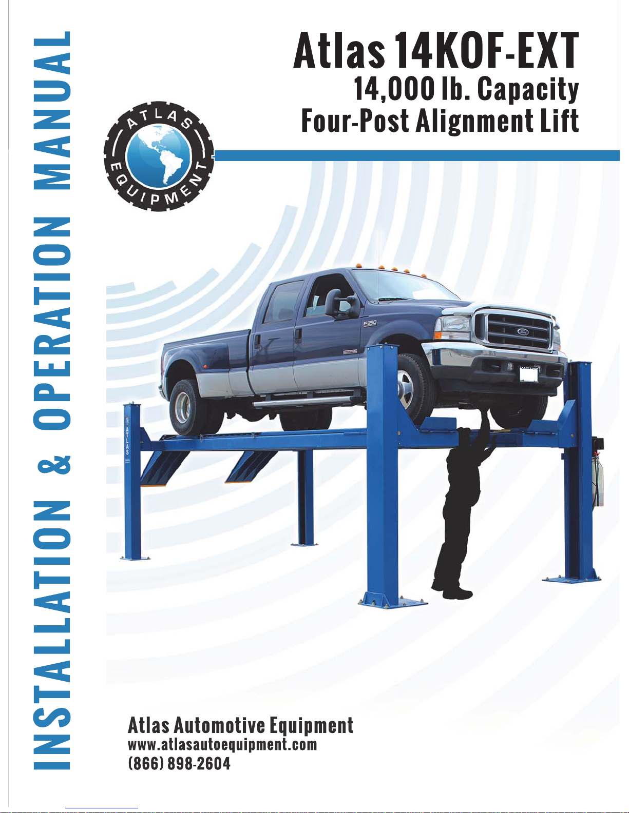
Page 1
Page 2

Revised 9/5/2018
Read this entire manual before operation begins.
Record below the following information which is located on the serial number
data plate.
Serial No.
Model No.
Date of Installation
Page 3

Contents
Specifi cations. . . . . . . . . . . . . 4
Important Information . . . . . . . . 6
Tools Required for Installation . . . . . 7
Anchoring Tip Sheet. . . . . . . . . . 8
Installation . . . . . . . . . . . . . . 9
Operation Instructions. . . . . . . . . 25
Maintenance Schedule. . . . . . . . . 26
14KOF-EXT Parts List . . . . . . . . . 30
Warranty . . . . . . . . . . . . . . . 51
Page 4
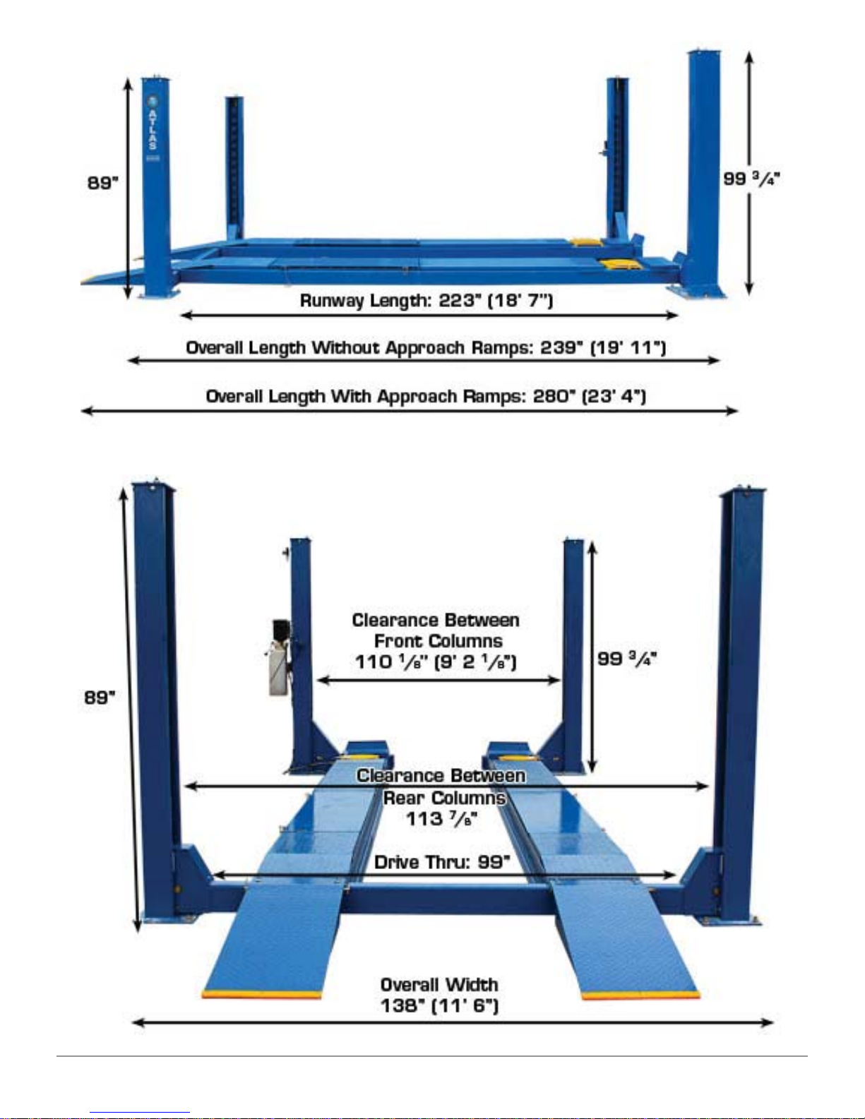
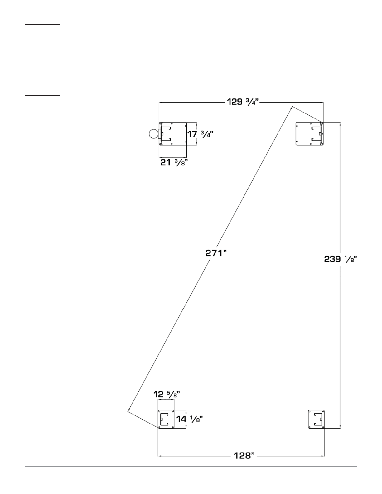
Specifi cations
Capacity 14,000 LB.
Motor 220volt Single Phase Range 208-230 VAC
Lifting Height 69 7/8”
Clearance Under Runways 61 1/2”
Overall Width 138”
Overall Length with Approach Ramps 280”
Overall Length without Approach Ramps 239”
Length of Approach Ramps 49 1/4”
4-Wheel Alignment Wheelbase
2-Wheel Alignment Wheelbase
Runway Length 223”
Width Between Runway Rails 39 1/8”
Outside Runway to Outside Runway 82 1/2””
Runway Width 19 3/4”
Thickness of Runway 8 3/8”
Width Between Runways 42 5/8”
Height of Columns
Column Dimension
Base of Column
Clearance Between Columns
Maximum 162”
Minimum 81”
Maximum 178”
Minimum 81”
Rear: 89”
Front: 99 3/4”
Rear: 6” X 9 1/2”
Front: 7 1/2” X 11”
Rear: 12 1/2” X 14 1/4”
Front: 17 3/4” X 21 3/4”
Rear: 113 7/8”
Front: 110 1/8”
Outside Column to Outside Column
Specifications 4
Rear: 125 3/4”
Front: 125 1/8”
14KOF-EXT
Page 5
Specifications 5
14KOF-EXT
Page 6

Important Information
Please read this manual thoroughly before installing and operating the lift.
Warning: It is diffi cult to collect for damaged or lost items after you have given
the freight carrier a clear reciept. If there is any damage to the product before
assembly, notify the carrier at once! Ideally, freight damage should be reported
to the freight carrier with a freight claim established at the time of drop off. We
are not responsible for freight damage. Shortages or damage also must be
reported within 7 business days to your local Atlas distributor.
The concrete fl oor where the lift will be installed must be a minimum of 4” in
thickness. The concrete must have a minimum compressive strength of 3,000
PSI. Failure to comply could result in personal injury, property damage and / or
unsatisfactory lift performance.
Do not raise the vehicle on the lift until the lift has been installed and adjusted
correctly as described in this manual.
Lubricate all cable sheaves, bearings and shafts before installing the lift.
Motors and electrical components are not sealed against the weather and
moisture. Install the lift in protected indoor location or use a protective cover for
the motor.
Use AW 32 or AW 46 hydraulic fl uid. Do not use TRANSMISSION FLUID.
Important Information 6
14KOF-EXT
Page 7

Tools Required for Installation
Concrete Rotary Hammer Drill with ¾” carbide drill bit
12” Crescent Wrench
Open End Wrench Set
Phillips & Flat Head Screwdriver
Sledge Hammer
Retainer Ring Pliers
Electrical Pliers
4 foot Level
25 foot Tape Measure
Step Ladder
3 Gallons of Hydraulic Oil, SAE-10 or equivalent (AW 32 or AW 46)
Installation will take a minimum of 6 people. A forklift or other hoisting
device will make the installation easier.
Tools Required for Installation 7
14KOF-EXT
Page 8
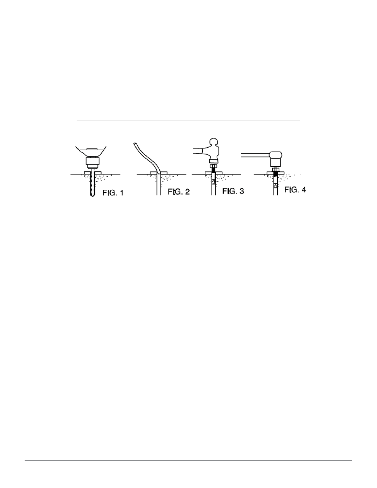
Anchoring Tip Sheet
1. Use a concrete hammer drill with a carbide tip, the same diameter as the
anchor, 3/4”. Do not use excessively worn bits or bits which have been
incorrectly sharpened.
2. Keep the drill in a perpendicular line while drilling.
3. Let the drill do the work. Do apply excessive pressure. Lift the drill up and
down occasionally to remove residue to reduce binding.
4. Drill the hole to depth equal to the length of anchor.
5. For better holding power, blow dust from the hole.
6. Place a fl at washer and hex nut over threaded end of anchor, leaving
approximately 1/2 inch of thread exposed, and carefully tap anchor. Do not
damage threads. Tap anchor into the concrete until nut and fl at washer are
against base plate. Do not use an impact wrench to tighten. Tighten the nut,
two or three turns on average concrete (28-day cure). If the concrete is very
hard, only one or two turns may be required.
Anchoring Tip Sheet 8
14KOF-EXT
Page 9
Installation
IMPORTANT NOTICE
These instructions must be followed to insure proper installation and
operation of your lift. Failure to comply with these instructions can result
in serious bodily harm and void the product warranty. Manufacturer
will assume no liability for loss or damage of any kind, expressed or
implied resulting from improper installation or use of this product.
Please read entire instruction before
starting to assemble the lift
STOP!!!!
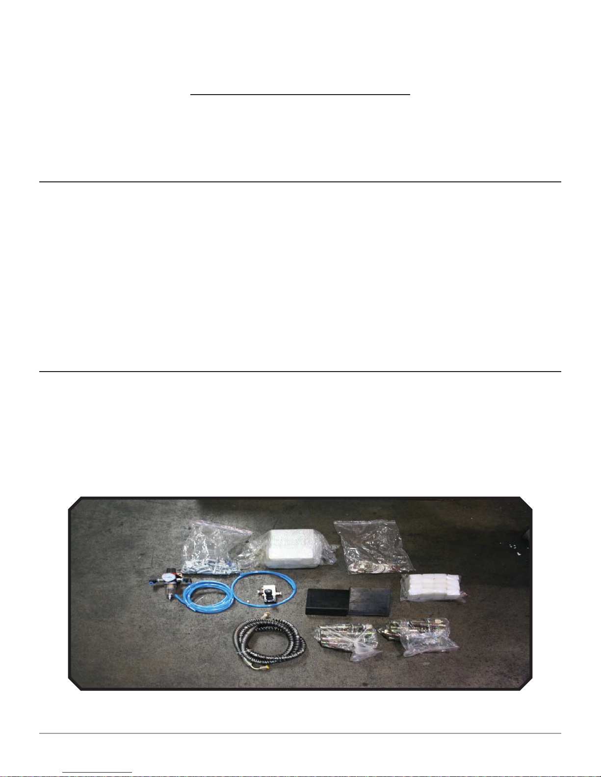
Open up the parts box and verify all parts are present
Installation 9
14KOF-EXT
Page 10
STEP 1: {Unloading & Unpacking}
1. After unloading the lift, place it next to the installation sight.
2. Remove the shipping bands and packing materials.
3. Remove the packing brackets and bolts holding the two columns together. Do
not discard the bolts; some may be needed in the assembly of the lift.
STEP 2: {Site Layout}
1. Once a location
is determined,
use a carpenter’s
chalk line to layout
a grid for the
column locations.
(CAUTION)
Keep all of the
dimensions square
to ensure proper
operation and avoid
damage to the lift.
2. Before assembling
the lift, drive
a vehicle into
the installation
position to check
for adequate
clearance.
3. Note: All four
columns need to
be level and square
from front to back
and side to side.
Installation 10
14KOF-EXT
Page 11
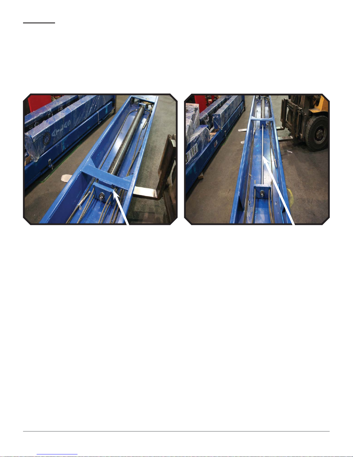
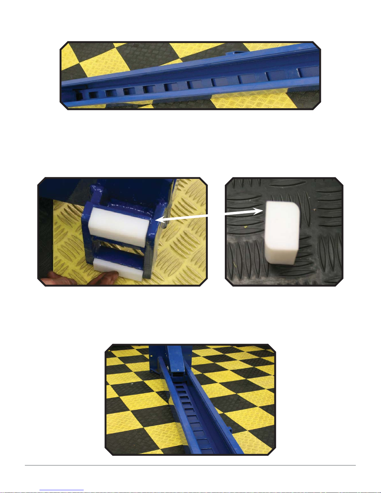
STEP 3: {Locate the Lift Components}
1. Use a forklift or other lifting device to move the runways into the desired
location. The cylinder runway must be positioned on the driver’s side. Use
wooden blocks or jack stands under the runways to set them about 12 inches
off of the ground and parallel to each other.
2. Turn the runway with the cylinder over. By hand, pull the cylinder shaft out to
its maximum length.
Before After
3. Place the columns and cross beams near their relative positions. The column
with the power unit mounting bracket will be positioned on the driver’s front.
Installation 11
14KOF-EXT
Page 12
STEP 4: {Rear Cross Beam}
1. Remove the pins on both ends of the rear cross beam. The pins will be
reinserted after the cables are routed. The pins hold the cables up in the
pulleys so they do not slip off. This same step will need to be completed on
the front cross beams.
Remove C-clip
2. Lay each rear column down facing upward. The rear Columns are 89” in length.
3. Insert the short locking ladders into the rear columns. Set the columns
upright into their relative positions.
Short Ladder
Long Ladder
Installation 12
14KOF-EXT
Page 13
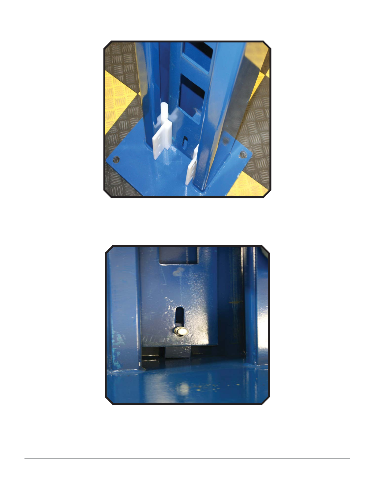
4. Maneuver the white wear blocks into the columns so the slotted ends mesh
with the lock ladder. There are 2 wear blocks per side.
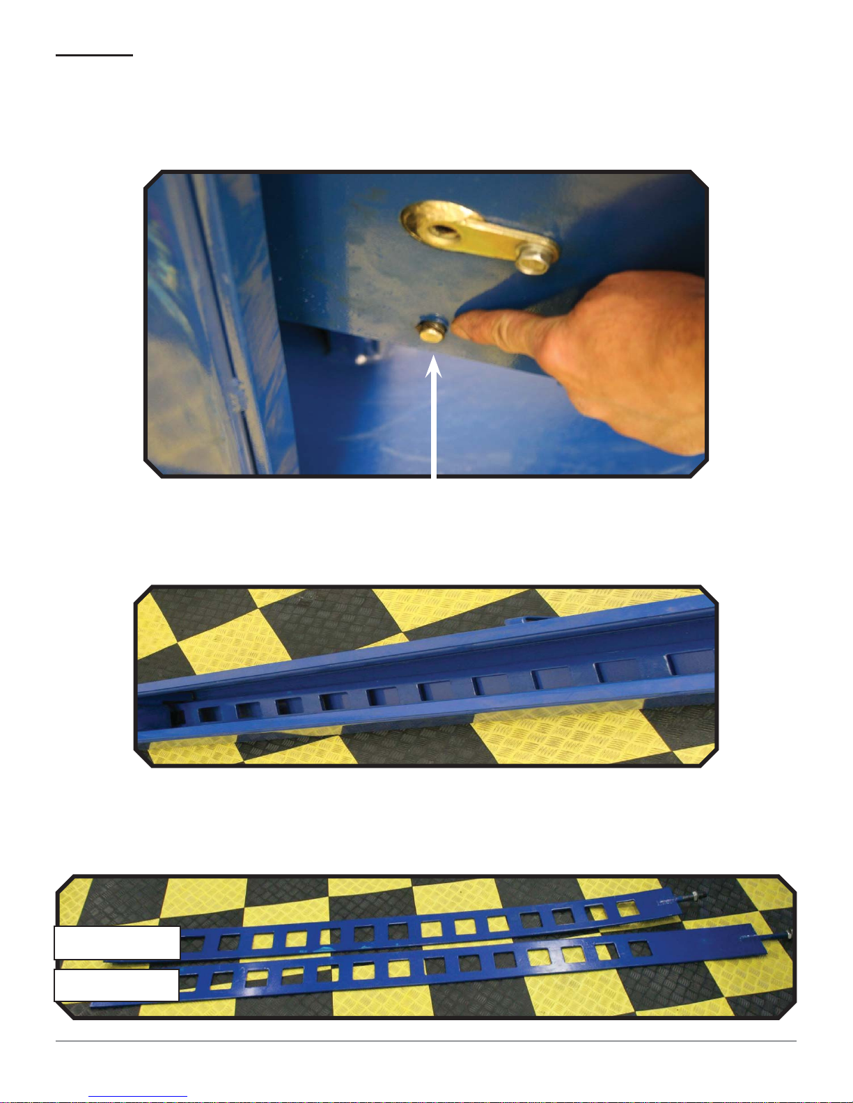
5. Using the bolt supplied at the bottom of the column, attach the short lock
ladders. Do not tighten the bolt.
Installation 13
14KOF-EXT
Page 14
6. Bolt on the top cap. Pay close attention to the top caps. There is a left side
and a right side.
Cable Holes
Lock Ladder Holes
7. Insert the top of the short lock ladder through the top cap. Bolt down the top
cap until ½ inch of thread is exposed at the top.
Installation 14
14KOF-EXT
Page 15
8. Maneuver the rear crossbeam into each column. Screw the wear blocks to the
rear cross beam: 12 pan head screws supplied.
STEP 5: {Front Cross Beams}
1. Remove the pins on both ends of the front cross beams. The pins will be
reinserted after the cables are routed. The pins hold the cables up in the
pulleys so they do not slip off.
Installation 15
Remove C-clip
14KOF-EXT
Page 16
2. Lay each front column down facing upward. The front Columns are 99 3/4” in
length.
3. Insert white wear blocks into the front cross beams’ carriages. There are 4
white wear blocks per side. Make sure the rounded edge of the white wear
block is facing outward. The rounded edge makes contact with the inside
corners of the column.
4. Pick up the cross beams and slide them into the columns. Make sure the cross
beams are pushed to the bottom of the columns. It helps to have 2 people for
this procedure.
Installation 16
14KOF-EXT
Page 17

5. Insert the long locking ladders through the cross beams. Using the bolt
supplied at the bottom of the column, attach the long lock ladders. Do not
tighten the bolt. (Refer back to Installing Rear Cross Beam steps 3 & 5.
6. Bolt on the top cap. Pay close attention to the top caps. There is a left side
and a right side. (Refer back to Installing Rear Cross Beam step 7.
7. Insert the top of the long lock ladder through the top cap. Bolt down until ½
inch of thread is exposed at the top.
8. Set both front columns upright and as close to their relative position.
STEP 6: {Runway Installation}
1. The runways should already be positioned in their relative positions and
elevated above the front and rear cross beams. If not, do this now.
2. Leave working space between runways and cross beams so the cables can be
routed into their home positions. Connect the air lock lines at this time.
Note: Working space
for installing equalizing
cables and air lock lines.
Note:
Air Lock Line
3. Route each equalizing cable into their positions. The longest cable is the
Passenger front (421.4”). The 2nd long cable is the driver’s front (359.3”).
The 3rd long cable is the passenger rear (218.2”). Shortest cable is the
driver’s rear (156.1”).
Installation 17
14KOF-EXT
Page 18

4. When routing the equalizing cables through the cross beam pulleys, pay
close attention to the position of the equalizing cables to the small white
safety lock pulley. On the front cross beams, the equalizing cables should be
routed over the small white safety lock pulley. On the rear cross beam, the
equalizing cables will be routed behind the small white safety lock pulley.
Note: The position of the
equalizing cable is in front of
the small white safety lock
pulley. Front cross beams.
Note: The position of the
equalizing cable is behind
the small white safety lock
pulley. Rear cross beam.
5. Install the runways. Do not tighten the bolts. Just make them snug. This will
allow for movement when plumbing and squaring the lift.
Installation 18
14KOF-EXT
Page 19

6. Double check all air lock lines for connection prior to installing the runways on
the cross beams.
Note: Install front
runway wheel stops
before bolting down
the runway.
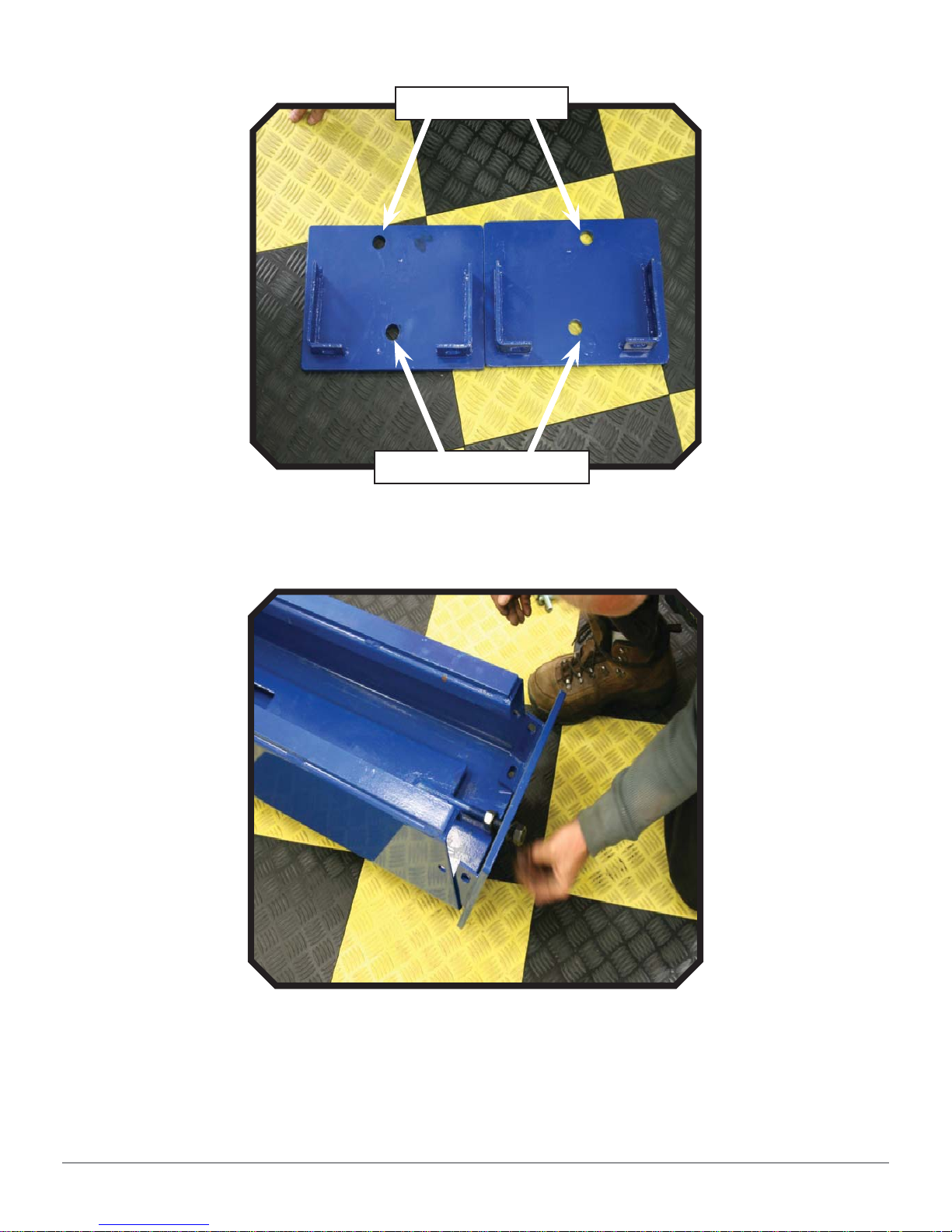
Note: Use these 2 bolt
holes on the front and
back of the runways.
STEP 7: {Anchoring the Lift}
1. Square all columns. This can be achieved by checking the angles from the
front driver’s side column base to the rear passenger side column base. Check
the square from the front passenger side column base to the rear driver’s
column base. A dead blow hammer or other tool may be needed to adjust
each column to true the squaring of the lift.
2. Use a hammer drill and a ¾” masonry drill bit and drill the anchor holes
through the holes on the base of the columns. Tap the anchors into place with
sledge hammer.
3. Using a level, plum each column. If needed, use shims provided in the parts
box.
4. Tighten anchors to 100 foot pounds.
5. Tighten the runway bolts to the cross beams.
STEP 8: {Cable Routing}
1. The cables are routed when the lift is packaged. During the installation
process, the cables may fall out of their primary positions on the cable sheave
(4 pulley stack).
2. Cable Identifi cation: Cable 1-Driver’s Front; Cable 2-Driver’s Rear; Cable
3-Passenger Rear; Cable 4- Passenger Front
3. Follow picture diagrams below for cable positions.
Installation 19
14KOF-EXT
Page 20

Cable Sheave Routing
4
1
3
2
4
Cylinder Cable Support
1
2
3
Installation 20
14KOF-EXT
Page 21

STEP 9: {Power Unit & Hydraulic Connections}
1. With the nuts, bolt and washers supplied, mount the 220 volt power unit to
the driver’s side column.
2. Thread the hydraulic (short) fi tting into the power unit’s valve body block and
connect the hydraulic hose.
3. Thread the hydraulic (longer) fi tting through the runway and tighten. Connect
the power unit hydraulic hose and cylinder hydraulic hose fi tting.
4. Fill reservoir with hydraulic fl uid. (3.5 gallons)
Hydraulic
(long) fi tting
Hydraulic
(short) fi tting
STEP 10: {Pneumatic (Air) Component Installation}
1. With the hardware provided, install the air lock control valve and the
regulator/moister trap. Connect pneumatic lines (provided). See photos below
for pneumatic line installation.
Installation 21
14KOF-EXT
Page 22

Main air supply
in. ¼” threaded
air receptacle.
Air in from
Air out to
pneumatic lock
control valve.
regulator
Installation 22
Air out to pneumatic
safety locks
14KOF-EXT
Page 23

STEP 11: {Runway Leveling}
1. Engage all 4 corners of the lift on the same lock level.
2. Check the level of the driver’s side runway by placing a level lengthwise on
the runway.
3. Adjust the runway by loosening or tightening the lock ladders accordingly.
4. Repeat procedures 2 & 3 for the passenger side runway.
5. Lay the level across opposing runways and adjust until level. This procedure
will be performed on the front and rear of the lift.
6. Double check all leveling points.
7. Tighten bolts on the bottom of the lock ladders
8. Connect runway approach ramps.
STEP 12:
{Electrical Connection}
1. Have a certifi ed electrician install a dedicated 30amp breaker.
2. Follow the diagram below for 220 volt motor wiring. Make certain that
the wires are installed in the proper legs of the AC contactor for normal
operation.
“UP” button
A1 and 3L2
Installation 23
Install wires from
electrical supply in these
2 terminals. 3L2 and 5L3
14KOF-EXT
Page 24

STEP 13: {Grease Fittings}
1. Insert grease fi ttings
STEP 14: {Pre-Operation Check List-Less Load}
1. Insert 3 to 4 drops of air tool oil in the air supply inlet. Repeat this at least
every 2 weeks. Connect air supply, set pressure to no more than 120psi
(8bar). Inspect for leaks.
2. Pressurize the hydraulics by pressing the up button on the power unit. Inspect
the hydraulic system for leaks.
3. Raise and lower lift at least 3 times while inspecting cable routing/function
and pulley rotation. Do not over heat or toggle the motor
4. Listen for locks to click at the same time while raising the lift.
5. If locks do not click at the same time (synchronize), repeat the procedures on
STEP 11: {Runway Leveling}.
Installation 24
14KOF-EXT
Page 25

Operation Instructions
To lift vehicle
1. Keep the work area clean and free of clutter
2. Drive vehicle to the Platform and put on the brake
3. Turn on the power and press the button UP, raise the lift to the working
position
Note: make sure the vehicle is steady when the lift is raised.
4. Push the handle on the release valve to rest the lift on the safety locks. Make
sure the safety device is locked at the same height.
To lower vehicle
1. Be sure there are no people or objects under the lift, only leaving operator in
lift area
2. Press the button UP until the lift has cleared the locks, press and hold the
manual-controlled air valve to release the safety device. Push the handle on
the lowering valve with the other hand. The lift will lower automatically.
3. Drive away the vehicle when the lift is lowered to the lowest position
Operation Instructions 25
14KOF-EXT
Page 26

Maintenance Schedule
Daily Inspection & Maintenance
1. Cleanliness: Cables, Columns, Runways and other lift parts should be kept
free of corrosive agents, solvents and road salts. If such agents are spilled
or splashed on any lift component, immediately rinse thoroughly with water
and wipe down with a clean rag. Spray wire rope cables as required with
Penetrating Oil and wipe down.
Failure to keep lift free of corrosive agents and solvents will lead to reduced
component service life, cable failure, etc., which could result in property
damage and/or personal injury.
2. Fasteners: Check all the attaching bolts and nuts for tightness.
3. Cables: Check wire rope cables for wear or damage. Any cable with broken
wires, severe corrosion, excessive stretch, deformed strands, variations in
diameter (necking), or any change from its normal appearance, must be
replaced. If any cable is found to be in need of replacement, the entire cable
set must be replaced immediately. Refer to fi gures below.
4. Sheaves: Check sheaves (pulleys) for wear or damage, i.e. wobble (tilt),
cracks, loose on pin, or excessive noise during operation.
5. Sheave Pins: Check for loose or missing sheave (pulley) pins.
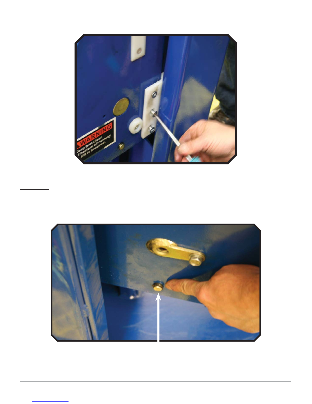
6. Locking Latches and Slack Cable Devices: Watch locking latches and
slack cable devices during lift operation to ensure that latches work
properly and line up with slots in latch plate located in columns.
Monthly Inspection & Maintenance
1. Cables: Clean wire rope cables with lift in both lowered and raised position by
spraying with Penetrating Oil and wiping the cable down.
2. Slack Cable: Inspect slack cables and pulley devices.
3. Column Anchor Bolts: Check column anchor bolts for tightness. Re-
torque anchors bolts to 100 ft/lbs. If anchors do not tighten to the required
installation torque, replace concrete under each column base per installation
instructions. Let concrete cure before installing lifts and anchors.
4. Columns: Look for corrosion, giving special attention to the area at the base of
the column. Check severely corroded areas by pecking with an awl or welder’s
Maintenance Schedule 26
14KOF-EXT
Page 27

chipping hammer. If column is corroded through at any point it must be
replaced immediately. If not corroded through, remove old paint and rust scale,
then coat with a high quality corrosion resistant paint. A thorough inspection
of the lifting system must be performed quarterly by qualifi ed lift service
personnel; more frequently (monthly) under extreme service conditions such
as outside installations or high usage (10 or more cycles per day, etc.).
Maintenance Schedule 27
14KOF-EXT
Page 28

Quarterly Inspection & Maintenance
1. Cables: Inspect cables in both lowered and raised position. The cables may
also be viewed through various inspection holes and openings in yokes and
runways. Check all the following:
a. That cables have no broken wires visible, reference Daily Inspection &
Maintenance.
b. That cables are free of severe corrosion and pitting, reference Daily Inspection
& Maintenance. A light surface corrosion on exposed outer wires is normal.
Penetrating Oil should be applied during monthly periodic inspection.
c. That there are no areas on the cable that have a greatly reduced diameter or
“necking”, reference Daily Inspection & Maintenance. When any cable is found
with excessive necking, all cables must be replaced immediately.
d. That cables do not have excessive stretch. It is normal for new cable to require
adjustment during “break in”, after which small periodic adjustments may be
required. However, if a cable that has been in service for 6 months should
suddenly require frequent adjustments or has used all the cable adjustment
available, all cables must be replaced immediately.
e. If any cable is found to be in need of replacement, the entire cable set must
be replaced immediately.
f. Cables are expendable items and should be replaced as a set every 20,000
cycles (estimated) or every 6 years, unless earlier replacement is indicated
during inspection.
2. Sheaves and Pins: Inspect sheaves and pins in yokes and runways.
Sheaves are expendable items. Sheaves and pins should be replaced
when worn. Use of sheaves and pins with excessive wear will lead to
reduced service life of cables.
2.1. Inspect sheaves (pulleys) in yoke ends with lift in lowered position or
resting on the locking latches.
a. Hold lowering handle down and pull on cable in column to create slack in cables.
b. Check for excessive side to side wobble. Grasp rim of sheave and attempt to
wobble (tilt) side to side. If sheaves wobble (tilt) more than 3/16” (4.8 mm)
side to side or move up and down on shaft more than 1/32” (0.8mm), the
sheave and pin (shaft) should be replaced.
c. Check sheaves and replace if cracks are found.
d. Check for ease of rotation. If sheaves do not turn freely, the sheave and sheave
pin should be removed, inspected, lubricated, and reinstalled or replaced.
Maintenance Schedule 28
14KOF-EXT
Page 29

2.2 Fully raise lift. Inspect sheaves (pulleys) in runway ends with lift in raised
position.
a. Visually inspect alignment of sheaves. Misalignment of sheave(s) indicates
excessive wear; the sheave(s) and sheave pin should be removed and
inspected. Replace as required.
b. Hold lowering handle down to lower lift onto latches. Pull on cables under
runway to create cable slack.
c. Check for excessive side to side wobble. Grasp rim of sheave and attempt to
wobble (tilt) side to side, refer to fi gures above. If sheaves wobble (tilt) more
than 1/16” (1.6 mm) side to side, or move in and out more than 1/32” (0.8
mm), the sheave and sheave pin (shaft) should be replaced.
3. Hydraulic Cylinder: Inspect the hydraulic cylinder mounting to the runway.
Inspect cylinder and hydraulic hoses for leaks. Repair or replace as required.
3.1. Check and tighten the hydraulic cylinder rod nuts holding the cable pull
bar.
4. TRACKS for Rolling Jack: Inspect rolling jack tracks for cleanliness,
corrosion, excessive wear or damage. Clean dirty tracks. Worn or damaged
tracks must be repaired immediately. Failure to do so will lead to reduced
service life which could result in property damage and/or personal injury.
5. Latch Inspection and Adjustment: Check locking latches for proper
operation. Inspect for worn or missing parts. Replace worn or damaged parts
and adjust as required.
6. Check latch operation on all four corners.
7. Latch and Latch Bar Line-Up: Observe locking latches during lift operation
to ensure that all latches line up with slots in latch bar located in all four
columns. If not, relocate and/or re-shim columns.
8. Check slack cable devices for proper operation
9. Inspect for worn or missing parts: Replace worn or damaged parts as
required.
10. Observe both locking latches and slack cable devices during lift
operation to ensure that all latches line up with slots in latch bar
located in all four columns.
Maintenance Schedule 29
14KOF-EXT
Page 30

14KOF-EXT Parts List
ITEM DESCRIPTION QTY REMARK
1 Beam weldment(master, open side) 1
2 Beam weldment(slave, open side) 1
3 Beam weldment(close side) 1
4 Platform weldment(slave side) 1
5 Platform weldment(master side) 1
6 Ramp weldment 2
7 Baffl e2
8 sliding plate weldment 2
9 Small ramp weldment 2
10 Surface mount plate 2 610*500
11 Frame of sliding plate 2
12 Surface mount plate 2 1720*500
13 Cover plate A for turntable position 4 100*500
14 Cover plate B for turntable position 2 300*500
15 Cover plate C for turntable position 2 520*500
16 Limited plate 2 125*500
17 Flat washer φ12 78
18 Spring washer φ12 62
19 Nut M12 44
20 Hexagon screw M10*3.5 4
21 Spring washer φ10 7
22 Flat washer φ10 7
23 Sliding plate pin 4
24 Pin ring 8
14KOF-EXT Parts List 30
14KOF-EXT
Page 31

25 Pin chain 4
26 Spring of sliding plate 8
27 Wheel of sliding plate 88
28 Limited washer of sliding plate 4
29 Space bush of cable pulley 1
30 Hexagon nipples M12*40 16
31 Screw M8*20 24
32 Sliding block 8
33 Small sliding block 16
34 Jump ring φ12 8
35 Limited pin of cable 4
36 Stop block 8
37 Screw M6*15 16
38 Space bush for latch 4
39 Shaft of latch 4
40 Safety hook for latch(left) 2
41 Safety hook for cable broken 1
42 Limited wheel pin 4
43 Limited wheel 4
44 Flat washer φ821
45 Spring washer φ817
46 Pulley shaft 4
47 Hexagon nipples M6*30 8
48 Air cylinder for latch 4
49 quickly fi tting for air cylinder 4
50 Gasket 4
51 "V" air fi tting 4
52 Nut M6 8
53 Pulley of the beam 4
14KOF-EXT Parts List 31
14KOF-EXT
Page 32

54 Spacer bush 4
55 Hexagon nipples M8*15 9
56 Flat washer φ40 18
57 Cover 2
58 Spring washer φ610
59 Flat washer φ610
60 Spring for latch 8
61 Grease fi tting 9 M10*1
62 latch 1
63 Right latch 2
64 Screw M6*12 8
65 Nut M8 8
66 Hexagon nipples M8*30 4
67 Handle valve 1 XG86522
68 Air hose φ8 1 PU8*5-800
69 9/16 Hydraulic hose 1 9/16-2340
70 Power unit 1 23MPA-1.6
71 Air hose φ8 1 PU8*5-2600
72 Oil water separation 1 AFR2000
73 Column(slave, open side) 1
74 Column(master, open side) 1
75 Cotter pin 5
76 Big nut of cylinder 1 M30
77 Lock block of cable 1
78 Pull block for raising 1
79 Nylon sliding block of cylinder 2
80 Screw M6*15 4
81 Column weldment(slave, close side) 2
82 Cover plate for close, left column 1
14KOF-EXT Parts List 32
14KOF-EXT
Page 33

83 Cover plate for close, right column 1
84 Cover plate for open side column 1
85 Top cover for master column 1
86 Nut M20 8
87 Nut M5 6
88 Yellow warning strip for ramp 2
89 Screw M5*20 6
90 Flat washer φ56
91 Pin for ramp 2
92 Hydraulic cylinder 1 φ90/φ100-1760
93 Nut M12 18
94 Copper backing 1
95 9/16 Pipe fi tting 1
96 9/16 nut 1
97 Flat washer φ14 1
98 9/16 elbow fi tting 1
99 9/16 hydraulic hose 1 9/16-2020
100 Explosion trap 1
101 Copper backing 1
102 2G 3/8 Pipe fi tting 1
103 Cylinder support 1
104 Hexagon nipples M12*30 20
105 Nut M18 8
106 Flat washer φ18 8
107 Ladder for close side column 2
108 Flat washer φ20 8
109 Cable 1 L=5985
110 Cable 1 L=4405
111 Cable 1 L=11930
14KOF-EXT Parts List 33
14KOF-EXT
Page 34

112 Cable 1 L=10770
113 Cover plate of close side 2
114 Safety hook for Cable broken 2
115 Pulley shaft 1
116 Space bush 1
117 Pulley under the runway 8
118 Spacer bush 3
119 Spacer bush 3
120 Pulley shaft 3
121 Hexagon screw M10*40 2
122 Hexagon screw M10*20 1
123 Spacer bush of salve runway 1
124 Spacer bush of salve runway 1
125 Pulley shaft 1
126 Nut of handle valve 1
127 Air hose φ8 1 PU8*5
128 Air hose φ8 1 PU8*5
129 Air hose φ8 1 PU8*5
130 Air hose φ8 3 YPU8
131 Air hose φ8 1 PU8*5
132 Air hose φ8 1 PU8*5
133 Air hose φ8 1 PU8*5
134 Air hose φ8 3 YPE8
135 Air hose φ8 1 PU8*5
136 Ladder for open side column 2
14KOF-EXT Parts List 34
14KOF-EXT
Page 35

14KOF-EXT Parts List 35
14KOF-EXT
Page 36

14KOF-EXT Parts List 36
14KOF-EXT
Page 37

14KOF-EXT Parts List 37
14KOF-EXT
Page 38

14KOF-EXT Parts List 38
14KOF-EXT
Page 39

14KOF-EXT Parts List 39
14KOF-EXT
Page 40

14KOF-EXT Parts List 40
14KOF-EXT
Page 41

14KOF-EXT Parts List 41
14KOF-EXT
Page 42

14KOF-EXT Parts List 42
14KOF-EXT
Page 43

14KOF-EXT Parts List 43
14KOF-EXT
Page 44

14KOF-EXT Parts List 44
14KOF-EXT
Page 45

14KOF-EXT Parts List 45
14KOF-EXT
Page 46

14KOF-EXT Parts List 46
14KOF-EXT
Page 47

14KOF-EXT Parts List 47
14KOF-EXT
Page 48

14KOF-EXT Parts List 48
14KOF-EXT
Page 49

14KOF-EXT Parts List 49
14KOF-EXT
Page 50

14KOF-EXT Parts List 50
14KOF-EXT
Page 51

Warranty
This item is warranted for two (2) years on structural
components and one (1) year on air or electric hydraulic
power units, pneumatic power units, cylinders and major
components from date of invoice. Wear items are covered
by a 90 day warranty.
This LIMITED warranty policy does not include a labor warranty.
NOTE: ALL WARRANTY CLAIMS MUST BE PRE-APPROVED BY THE MANUFACTURER TO
BE VALID.
The Manufacturer shall repair or replace at their option for this period those parts returned
to the factory freight prepaid, which prove after inspection to be defective. This warranty
will not apply unless the product is installed, used and maintained in accordance with the
Manufacturers installation, operation and maintenance instructions.
This warranty applies to the ORIGINAL purchaser only, and is non-transferable. The warranty
covers the products to be free of defects in material and workmanship but, does not cover
normal maintenance or adjustments, damage or malfunction caused by: improper handling,
installation, abuse, misuse, negligence, carelessness of operation or normal wear and tear. In
addition, this warranty does not cover equipment when repairs or alterations have been made
or attempted to the Manufacturer’s products.
THIS WARRANTY IS EXCLUSIVE AND IS LIEU OF ALL OTHER WARRANTIES EXPRESSED OR
IMPLIED INCLUDING ANY IMPLIED WARRANTY OR MERCHANTABILITY OR ANY IMPLIED
WARRANTY OF FITNESS FROM A PARTICULAR PURPOSE, AND ALL SUCH IMPLIED WARRANTIES
ARE EXPRESSLY EXCLUDED.
THE REMEDIES DESCRIBED ARE EXCLUSIVE AND IN NO EVENT SHALL THE MANUFACTURER,
NOR ANY SALES AGENT OR OTHER COMPANY AFFILIATED WITH IT OR THEM, BE LIABLE
FOR SPECIAL CONSEQUENTIAL OR INCIDENTAL DAMAGES FOR THE BREACH OF OR DELAY
IN PERFORMANCE OF THIS WARRANTY. THIS INCLUDES, BUT IS NOT LIMITED TO, LOSS OF
PROFIT, RENTAL OR SUBSTITUTE EQUIPMENT OR OTHER COMMERCIAL LOSS.
PRICES: Prices and specifi cations are subject to change without notice. All orders will be
invoiced at prices prevailing at time of shipment. Prices do not include any local, state or federal
taxes.
RETURNS: Products may not be returned without prior written approval from the Manufacturer.
DUE TO THE COMPETITIVENESS OF THE SELLING PRICE OF THESE LIFTS, THIS WARRANTY
POLICY WILL BE STRICTLY ADMINISTERED AND ADHERED TO.
Warranty 51
14KOF-EXT
 Loading...