

Page 1
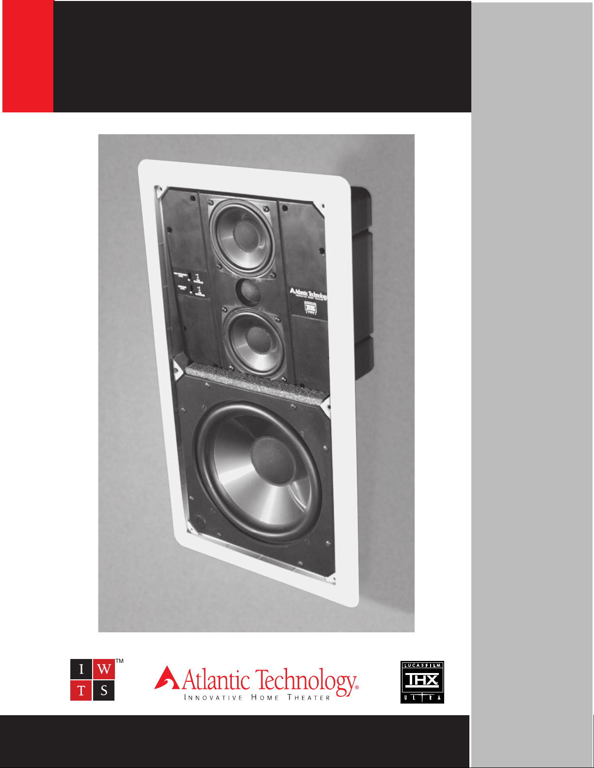
System 20 LCR and SR InWall Speakers
System 20 LCR and SR InWall
Theater System Speakers
Instruction Manual
● ● ● ● ● ● ● ● ● ● ● 1 ● ● ● ● ● ● ● ● ● ● ●
343 Vanderbilt Ave. Norwood, MA 02062 (781) 762-6300
www.atlantictechnology.com
Page 2

System 20 LCR and SR InWall Speakers
System 20 THX Installation Instructions
About These Speakers
System 20 by Atlantic Technology is a high performance home theater and music sound speaker system
designed to mount in the walls of your home. The system consists of a three-way full range front satellite,
System 20 LCR, and a switchable Dipole/Bipole surround speaker, System 20 SR. We recommend completing
the system (especially for movie reproduction) with the addition of a THX certified subwoofer like the Atlantic
Technology 372 PBM.
Please take a moment to read it over.
Some Surround Issues
The System 20 LCR is designed for the front three channels in a THX Ultra certified home theater system or as
a high quality music reproducer in a stereo system. Although it could be used as a surround speaker in a home
theater system, it doesn’t create the same kind of involving, believable surround field that the System 20 SR
Dipole surround speaker will. However, if you decide to use direct radiators for the primary surround or additional rear channels in 6.1 or 7.1 channel systems the System 20 LR (or the System 10 speaker) may certainly
be utilized.
The following section details important features and capabilities of these speakers.
The System 20 LCR Midrange/High Frequency Baffle
The midrange-tweeter assembly of the System 20 LR can be tilted approximately 5 degrees up or down by
removing the included leveling spacer located under the baffle. (Please see Figs. 1, 4 & 5). This lets you aim
these elements for better performance when the speaker must be placed
higher or lower than ideal. The mid-high baffle may also be rotated 90 degrees to allow horizontal placement of the speaker with no compromise in
performance. (Please note that
between studs centered on 16 inches without structural modification to the
studs and/or wall
though the frequency response at the listening position will be improved by
tilting the baffle, the sound will noticeably come from above or below the
screen and may not be as “realistic” as when it comes from ear level. For
further information and detailed instructions on angling and rotating this assembly please see Page 6
.) However, if the speakers are placed high or low, even
the System 20 LCR will not fit horizontally
.
System 20 LCR High Frequency and Midrange Level Controls
There are two switches located on the mid-high baffle that are accessible by
removing the grille. You can change the switch settings with your fingernail or
a small pointed object, such as a ball point pen. The High Frequency switch
adjusts the output level of the tweeter and therefore the upper range of sounds
that are reproduced (these include cymbals, bells, etc.). The Midrange control operates exactly like the High Frequency Control but affects the middle
range frequencies (human voices, etc.).
Tilting and rotating baffle
Fig 1
We strongly recommend that you try all three settings of both switches, using both music and movies (if the
System 20 LR is part of a home theater system). Please note that recordings vary in their sonic balance so try
several different discs before deciding. Try to achieve the best balance of natural overall sound with good detail
and clarity. The switch settings are “Normal/THX” in the lower position, “-2dB” (decreases mid or high frequency
output) in the middle position, and “+2dB” (increases mid or high frequency output) in the upper position.
Take some time to determine the best overall sonic performance in your room. It’s definitely worth the effort.
● ● ● ● ● ● ● ● ● ● ● 2 ● ● ● ● ● ● ● ● ● ● ●
Page 3

System 20 LCR and SR InWall Speakers
The System 20 SR Dipole/Bipole switch
When the System 20 SR absolutely must be located in a place that is not Dipole friendly (e.g. in the ceiling; well
behind the listening position, etc.) it can be easily switched to a Bipole configuration using the switch located
under the grille. In such cases it is advisable to try the speaker in both operating modes and with several
different sound tracks to determine which produces the most realistic surround field at the listening location.
Important Considerations Before Installation
Locations of Choice
Assuming that you’ll be using these speakers for more than simple background listening here are some placement recommendations:
Location, Location, Location
The single biggest determinant of any speaker’s ultimate sound quality is the room and the speaker’s location
in it. With in-wall speakers there are fewer placement options than with box speakers, so giving some thought
to location is really important. Additionally, the wall your speaker is mounted in will affect its sound. The speakers of our InWall Theater Systems have been computer designed to maximize the benefits and minimize the
detrimental effects of in-wall placement. You’ll find that Atlantic Technology InWall systems sound better than
most, if not all in-wall speakers because of this careful and sophisticated design process. In addition, the
System 20 LCR can optionally be used with an in-wall enclosure specifically designed to both optimize performance and offer a level of sound isolation for adjacent rooms.
Stereo Systems
The following applies should you be using the System 20 LCR front speakers in an audio only setting. For
stereo music reproduction the speakers are best located with the tweeters at approximately ear level when
seated, both on the same wall, facing the prime listening location. A separation of approximately six to eight feet
between the left and right speakers generally delivers the best imaging and sound staging. Ideally, the distance
between the two speakers will be the same as the distance from the speakers to the listening position, so the
three points form an equilateral triangle. In general, placement on one of the shorter walls will deliver the best
sound in a rectangular room. If you have to mount the speakers higher than ideal you should tilt the mid-high
baffle as outlined below. Or you may also mount the speakers “upside down”, with the mid-high baffle at the
bottom of the assembly for better positioning.
Sound reflects from room surfaces just like light; hard surfaces create lots of reflections and soft surfaces tend
to absorb them. Try to be aware of the speaker’s location in terms of proximity to glass, heavy drapes, and other
highly sound reflective or absorptive surfaces. A simple pair of strategically placed curtains or a wool wall
hanging can make a huge difference in sound quality and/or intelligibility! Also note that circumstances like one
speaker being located directly adjacent to a glass wall with the other speaker located by an open archway will
make the two speakers sound dramatically different. Therefore, the more similar the speaker’s surroundings,
the more even and consistent the sound.
When bass reflects from room surfaces, it can create some locations that are bass heavy and other areas that
are bass shy. These reflections are known as standing waves and they occur in most every room. When using
an external subwoofer it’s strongly recommended that you try several placements within the room to find the
best location for bass performance. Pay particular attention to the transition between the satellites and the
subwoofer, in addition to the deepest bass. For further information on subwoofer placement and setting system
levels please contact your installer or Atlantic Technology directly.
If there are bass standing wave problems when in-wall speakers are utilized full range the only real options are
to change the listening position or add a subwoofer that can be located in a “better bass place” in the room.
● ● ● ● ● ● ● ● ● ● ● 3 ● ● ● ● ● ● ● ● ● ● ●
Page 4

System 20 LCR and SR InWall Speakers
Home Theater Speaker Locations
Today’s home theater systems require you to place six or more speakers in your room; front left, front center,
front right, two surrounds, and a subwoofer. Some other systems include additional rear surround channels to
further the illusion of total involvement. And placement for all these speakers is potentially more critical than
with pure music reproduction alone.
in the movie theater; it’s to put you in the movie!
restaurant, the office, or wherever the video scene is taking place, and the sound system has the responsibility
of creating that part of the illusion.
Left/Center/Right Locations
The front three speakers ideally should have the tweeter at ear height when seated, just as with stereo speakers. Unfortunately, the presence of the television can make this difficult, if not impossible to accomplish. (Unless
you’re using a front projector and a perforated screen with the center channel speaker directly behind it). The
closer you can get to this ideal the better, however. Try to keep the left and right speakers within 3 feet of either
side of the TV screen. If possible, place the left and right speakers no more than 2 feet above or below the
height of the center channel speaker. The center speaker itself should be centered on, and directly above or
below the TV screen.
Ceiling Locations
Ceiling mounting of the System 20 LCR is not recommended due to its dispersion characteristics, weight, and
size. The System 20 SR may be ceiling mounted, but as outlined below its optimum performance will be
realized as a Dipole, placed directly to the sides of the prime listening position. It’s especially important, if you
mount any speaker in a ceiling, that you cover the back with a piece of fiberglass window screening to keep
insulation and other foreign matter out of the assembly. Should you be installing any speaker in a ceiling be sure
to install safety wires from the speaker to the structure above, to ensure security under all conditions. Please
see below for further information regarding mounting the System 20 SR in a ceiling.
That’s because the goal of setting up a good home theater isn’t to put you
That’s right, we want you to believe you’re in the jungle, the
The All Important Surround Speakers
For the record, we are strong proponents of Dipole surround speakers and recommend that you use
the System 20 SR as a Dipole, to the sides of the listening position, if at all possible.
In order to achieve THX Ultra performance use THX Ultra certified Dipole surround speakers like the System 20
SR. The following placement recommendations apply to all Dipole surround speakers (whether the System 20
SR or another model) Please try to follow them.
Dipole surrounds produce a diffuse, relatively non-localizable sound field that
projects to each side of the speaker. Directly in front of the speaker’s apex
there’s a sound “null” or dead zone (see Fig. 2)
When properly placed in the room, with the apex null aimed at the listeners,
this creates the illusion that the surround sound is coming from a large area
to both sides of the speaker! The result is that you’re immersed in the surround field and become one with the action taking place up on the screen.
Null
Surround Speaker Locations
The absolute best place for a Dipole surround is directly to the sides of the
prime listening position (+/- 15 degrees). They should be located no less than
Dipole speaker sound radiation
18 inches above ear height when seated and at least 24 inches below ceiling
level. If the surround speakers must be located closer than 24 inches to the ceiling they should be turned upside
down to keep the tweeters as far as possible from the ceiling. Please see the important note below.
System 20 SR surrounds are designed to mount horizontally, on the side walls. If they must be placed on the
back wall or the ceiling please follow these guidelines. On the rear wall, install the speakers horizontally at least
24 inches away from the corner, and between 18 inches above ear level when seated and 24 inches down from
the ceiling. If placed in the ceiling, position them with the drivers facing the front and back of the room with the
FIg.2
● ● ● ● ● ● ● ● ● ● ● 4 ● ● ● ● ● ● ● ● ● ● ●
Page 5

System 20 LCR and SR InWall Speakers
Left speaker to the left side of the room and the Right on the right side. As much as possible keep the null
centered on the prime listening position.
IMPORTANT: Please note that there are dedicated left and right Dipole surround speakers and they are
labeled as such. This is done to ensure that the drivers facing the front of the room are in phase with
the system’s front speakers. Left and right refer to the left and right wall when you are seated facing
the screen. If the speakers must be mounted upside down, as outlined above, be sure to swap them
from side to side in order to maintain proper phasing with the fronts.
In any case, please note that for the greater part of any movie you should not be directly aware of the surround
speaker’s presence. They’re there to create those environmental sounds
of the location up on the screen. So in a rain filled scene you should be
thinking, “Is it raining outside my house?”, not “Hey, I hear the rain in the
surround speakers!”
If you decide to use a direct radiator for the surrounds (in a non-THX
Ultra certified installation) keep the following in mind. When using nonDipole surround speakers, the more directly they are aligned with your
ears, the more localizable their sound will be. And since the vast majority
of movie surround channel information consists of environmental sonic
cues that aren’t supposed to be localized, this is particularly undesirable. Generally then, non-Dipole surrounds should be placed well above
ear level on the rear or side walls. As opposed to Dipoles, which work best when placed directly to the sides of
the listening position, direct radiators work best when placed on the side or rear wall, well behind, and not
aimed directly at the listening position.
Bipole operation (no null)
Fig 3
Now That You Have Chosen the Right Locations ... Installation Issues
IMPORTANT:
speakers, if at all possible. Note that
retrofit, except when the InWall back box enclosure is used (IN-BOX-20LCR) because the Installation Bracket
is pre-mounted in the enclosure. Please see the installation instructions for the IN-INST-20LCR or 20SR for
information pertaining to Installation Bracket mounting, and its use as a rough-in assembly in new construction.
The following instructions primarily apply to the final installation of the speaker system (either System 20 LCR
or System 20SR) into the already mounted Installation Bracket.
Horizontal or Vertical? To Tilt or Not to Tilt
The System 20 LCR can be mounted horizontally or vertically. However, when mounted horizontally it will
not fit between standard 16 inch on center studs. There is no practical benefit to mounting the speaker
horizontally, unless there is an issue of limited vertical space or aesthetics. If you wish to mount the speaker
horizontally in a 16 inch on center wall, modifications will have to be made to the wall framing.
Rotating and Tilting the Mid-high Baffle
If mounting the 20 LCR horizontally, remove the 8 mid/high baffle mounting screws and rotate the baffle 90
degrees as shown in Fig. 4. At the same time determine whether the mid/high baffle should be level or tilted up
or down. If the speakers are significantly above or below ear level (more than 2 feet) when seated, the baffle
should be tilted to compensate. While the 8 screws are removed, lift the mid/high baffle from the speaker and
remove the leveling spacer located under and within the baffle. The spacer is taped to the baffle at the top edge,
so cut through the tape before trying to remove the spacer. The spacer is flexible and can be removed without
disconnecting any wires. Simply lift one corner of the spacer over the baffle corner and then spread the spacer
while removing it the rest of the way. See Fig. 5 Rotate the baffle to achieve the desired tilt and reinstall using
the same 8 screws, being careful not to overtighten them. There is a strip of self adhesive acoustic foam
included in the Owners Manual packaging that should be attached to the flat section of the woofer baffle or
bezel assembly that has been exposed by tilting the baffle.
We always recommend a professional be involved in the installation of InWall Theater System
the Installation Bracket is required for all installations, new construction or
● ● ● ● ● ● ● ● ● ● ● 5 ● ● ● ● ● ● ● ● ● ● ●
Page 6

System 20 LCR and SR InWall Speakers
Infrared Eye Repeater Opening
There’s a cutout located on the front of the System 20 LCR that’s designed to accept most IR repeater receivers. This cutout is located under the round Atlantic Technology “Wave logo” adjacent to the woofer. To remove
the Wave logo simply push it out from behind.
Rear Enclosure and Internal Wall Treatment
An optional enclosure is available for the System 20 LCR
(IN-BOX-20LCR). It’s designed to be used in new construction and must be installed before the wall board is applied.
The benefits this enclosure provides include optimum volume for the woofer and a level of sound isolation for the
adjacent room. The optional enclosure comes with the Installation Bracket pre-installed.
You can also create an enclosure within the wall that provides the required cubic volume. The larger the volume, the
better the bass response will be, up to 1 cubic foot. Beyond
this size there will be little if any effective performance gain.
Set up for horizontal installation
FIg. 4
thin materials, yet it should not physically contact the back of the speaker. Typically then, the back wall material
will be roughly 1/8 to 1/4 inch (3 to 6mm) thick. You can also build a fire break type of enclosure by installing 2
x 4 or 2 x 6 cross members in the wall at appropriate positions. For the best performance the edges of the studs
should be caulked with an all weather silicone caulking material.
Please note that there is very little room behind the 20 LCR
in a standard “2 x 4” wall cavity (approx. 1/4 inch, 6mm), so
the back of any enclosure box must be made from relatively
Fill the wall cavity with insulation, observing all the relevant instructions from the insulation manufacturer. If
you‘ve built a back box, use tufted Dacron (available at craft stores as pillow filling) or fiberglass in the enclosure. There should be no insulation directly behind the actual speaker assembly.
The System 20 SR is much less critical of wall cavity volume than the LCR, and is typically not called upon to
deliver significant deep bass response. Still, follow the above recommendations regarding cavity insulation.
Using The Rear Installation Bracket Kit For Rough-In in New Construction
The required Installation Bracket kit (IN-INST-20LCR or 20SR)
includes everything necessary to create a rough-in kit for easing
installation in new construction. There are a pair of “wings” that
attach to the rear bracket and are then attached to the studs. The
rear Installation Bracket then acts as both a place holder for the
speaker system, in addition to being the clamping device when the
speaker is mounted in the wall. Instructions for its use are included
with the kit. Once the Installation Bracket has been installed proceed as detailed below.
Installation
The following instructions cover both the System 20 LCR and SR.
When the Installation Bracket has been used with the included
wings as a rough-in device in new construction, proceed directly
to Step 4.
The mid/high baffle shown removed for clarity with the
removable leveling spacer. The spacer can be
removed for tilting without disconnecting the assembly
Fig 5
from the speaker.
Cutting the Opening - Installing the Installation Bracket
After determining the best location for the speaker as outlined above, use the template (enclosed in the Installation Bracket kit) to cut the proper size hole in a retrofit installation (LCR - 17 13/16” x 9 3/8”, SR - 11” x 14 3/8”).
It’s very important to cut the hole level as there is no “play” between the speaker and the Installation Bracket.
● ● ● ● ● ● ● ● ● ● ● 6 ● ● ● ● ● ● ● ● ● ● ●
Page 7
System 20 LCR and SR InWall Speakers
IMPORTANT: Exercise extreme care before making any wall cuts to ensure that you will not cut through
any wires, pipes, or other items that may be in the wall. You may sometimes, but not always, be able to
determine the approximate location of wires and pipes by looking at the locations of nearby outlets
and plumbing. But their presence or absence is never an assurance that there is not something within
the wall cavity.
There must be a minimum depth behind the wall face of 3 5/8 (92mm). As noted above, be sure to keep the
edges of the cut out at least 1 inch (25mm) away from any stud or obstruction. The speaker assembly itself (the
part with the drivers mounted in it, the trimming bezel, etc.) is designed to mount to the Installation Bracket
after it has been installed within the wall.
Step 1. Tilt one corner of the Installation Bracket into the opening and continue to slide it fully into the wall cavity
until it fits completely into the cut out. Be sure to position the side extensions so they press against the inside
of the wall.
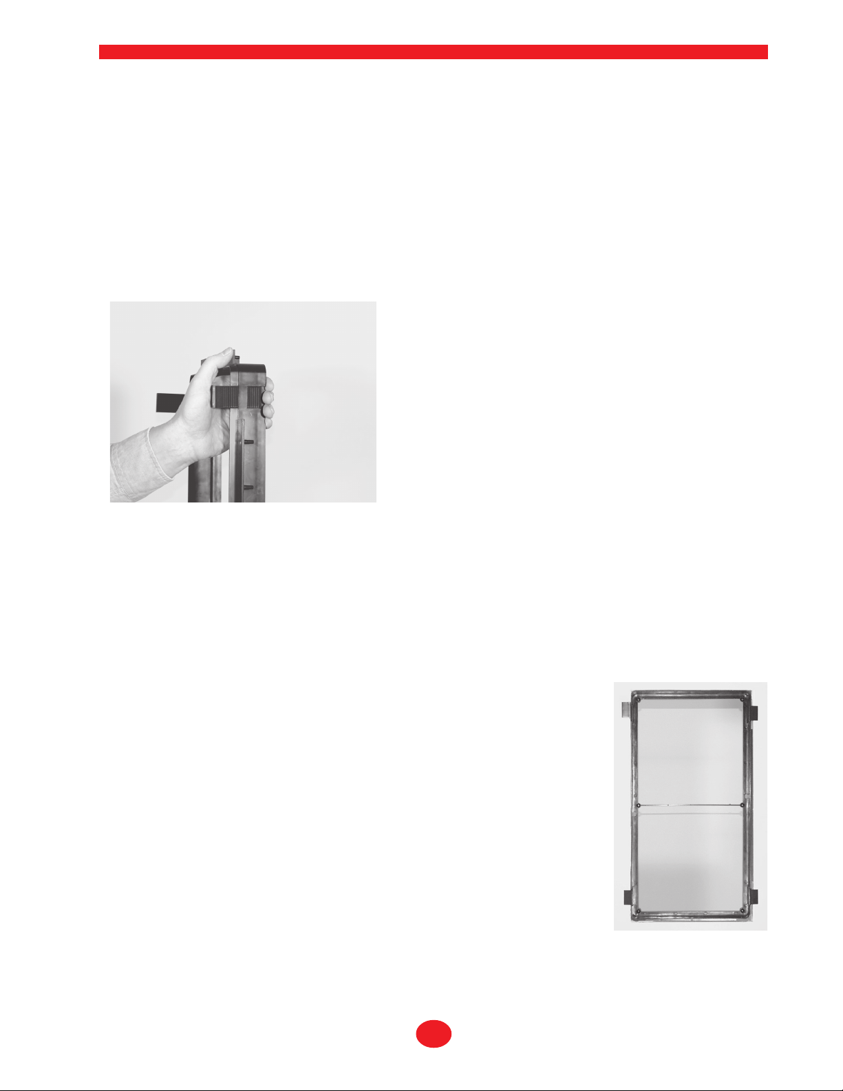
Step 2. Carefully insert the tabs into the Installation Bracket as
shown in Fig. 7. They are a tight fit and are best installed by
“clamping” them with your hand as shown in Fig. 6. Alternately,
there are predrilled holes in the side flanges of the Installation
Bracket that may be used to hold the assembly to the wall board
with #6 self-threading screws, instead of using the tabs. These
screws will be hidden by the speaker’s bezel when it is mounted.
Step 3. After the Installation Bracket is fixed in place note that
there are holes near the center of the long sides that can be
used to secure feed wiring using the included nylon wire ties.
Installing the tabs in the Installation Bracket.
Fig. 6
Shown outside the wall for clarity.
Step 4. Strip about ˚” of insulation from the connecting wires.
Connect them to the appropriate push terminal on the rear of
the speaker assembly, being careful to observe polarity (positive to the red terminal, negative to the black terminal). Typically, with standard “zip” cord wiring the marked wire
is used for the positive lead. Markings typically consist of a thread within one conductor, printing on the wire’s
insulation, a ridge or ridges on the insulation, or a flat side to the insulation.
Step 5. Carefully position the speaker assembly into the wall cutout and Installation Bracket. Check that it’s
level and then attach the speaker to the Installation Bracket with the included 3 inch #6 self-tapping screws. (If
the assembly is not level, you can oversize the wall opening very slightly to allow straightening the bracket and
speaker.)
Step 6. Tighten the mounting screws, which in turn will cause the bezel and the
Installation Bracket to clamp the wall board between them.
Be very careful not to
overtighten the screws as this can make the grille difficult or impossible to install.
The outer trim bezel has been specially designed to flex and conform to the wallboard. This makes for a good seal and eliminates rattles but it also means that the
speaker mounting screws should be snug, but not overly tight.
Installing and Removing the Grille
The grille is packed separately in the box with System 20 speakers. To install the
grille, press it carefully into the opening in the frame assembly. Since it’s designed to
fit snugly, please take your time and use care when installing the grille. Remove the
grille from the speaker using an awl or other pointed object in a grille opening near
one of the corners. Slowly pry the grille out, being careful not to damage the speaker’s
frame or its finish. If the grille is difficult to install, try loosening the speaker installation screws slightly.
● ● ● ● ● ● ● ● ● ● ● 7 ● ● ● ● ● ● ● ● ● ● ●
The Installation Bracket mounted
Fig. 7
in the wall using the tabs
Page 8

System 20 LCR and SR InWall Speakers
Painting the Bezel and the Grille
The bezel of the speaker assembly and the metal grille may be left as is or painted to match your décor. You can
paint the frame before or after it is installed in the wall. Use the included paint shield to protect against getting
any paint on the front of the speaker. Spray painting (using slightly thinned paint) is the best method to use for
painting the grille. If you paint the grille use air pressure to “blow out” any grille holes that become covered over
with paint. Be sure to use paint labeled safe for plastics. Many spray paints intended for use on wood and metal
contain solvents that are harmful to plastics and may damage the speaker assembly. Also, do not attempt to
clean any plastic parts of the speakers with solvents or any petroleum based products.
System 20 LCR Specifications
Drivers: 8 in. CCMG long throw woofer w/Butyl rubber surround and high power motor
Dual 3.5in. CCMG midranges w/Butyl rubber surrounds
1 in. natural silk dome tweeter w/Neodymium magnet and Ferrofluid cooling
Configuration: 3 way, D’Appolito array, magnetically shielded
Controls: Midrange Normal, +, - 2dB
High frequencies, Normal, +, - 2dB
Frequency Response: 56Hz - 20kHz +/-2dB
Sensitivity: 89dB, 1 watt, 1 meter
Impedance: 6 Ohms
Crossover points: 400Hz, 5.5kHz
Recommended power: 50 - 200WRMS
Optimum wall volume: 1.00 cu.ft.
Overall Dimensions: 19.09 x 10.63 x 3.7in., 485 x 270 x 94mm
Cutout dimensions 17 13/16 x 9 3/8in., 452 x 238mm
Installation kit: IN-INST 20 LCR required for all installations unless using the following InWall
enclosure
InWall enclosure: IN-BOX 20 LCR for new construction optionally available
Weight: 12 lbs.
System 20 SR Surround Speaker Specifications
Drivers: Dual 5.25in. CCMG midranges w/Butyl rubber surrounds
Dual 3/4 in. natural silk dome tweeters w/Neodymium magnet and Ferrofluid cooling
Configuration: Switchable Dipole or Bipole array
Frequency Response: 80HZ - 20kHz +/-3dB
Sensitivity: 87dB, 1 watt, 1 meter
Impedance: 6 Ohms
Crossover point: 3.5kHz
Recommended power: 50 - 200WRMS
Overall dimensions: 12.05 x 15.6 x 3.75in., 306 x 396 x 95mm
Cutout dimensions: 11 x 14 3/8in., 279 x 365mm.
Installation kit: IN-INST 20 SR required for all installations
Weight: 9lbs.
● ● ● ● ● ● ● ● ● ● ● 8 ● ● ● ● ● ● ● ● ● ● ●
Copyright, Atlantic Technology, 2000
All rights reserved
Specifications and details subject to
change for improvement without notice
Atlantic Technology
343 Vanderbilt Ave.
Norwood, MA 02062
781-762-6300
www.atlantictechnology.com
010-1020
 Loading...