


P-2000 7.1 Channel
Preamp/Processor/Tuner
Manual Instruction
2 |
Warnings |
Please Read First
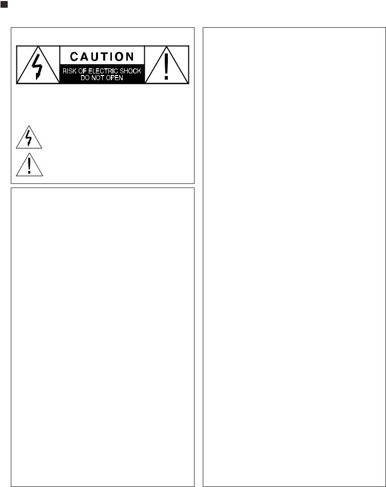
CAUTION: To reduce the risk of electric shock, do not remove the cover. No user serviceablepartsinside.Refertoqualifiedpersonnel.
WARNING: Toreducetheriskof fireorelectricshock,donotexposethisappliance torainormoisture.
The lightning flash with arrowhead,within an equilateral triangle,is intendedtoalerttheusertothepresenceofuninsulated“dangerousvoltage” within the product’s enclosure that may be of sufficient magnitude to constitute a risk of electrical shock to persons.
The exclamation point within an equilateral triangle is intended to alert theusertothepresenceofimportantoperatingmaintenance(servicing) instructions in the literature accompanying the appliance.
WARNING: Important Safeguards
ReadInstructions–Allthesafetyandoperatinginstructionsshouldbereadbefore theunitisoperated.
Retain Instructions–The safety and operating instructions should be retained for futurereference.
HeedWarnings–Allwarningsontheunitandintheoperatinginstructionsshould beadheredto.
FollowInstructions–Alloperatinganduseinstructionsshouldbefollowed.
Cleaning–Unplugtheunitfromthewalloutletbeforecleaning.Theunitshouldbe cleanedonlyasrecommendedbythemanufacturer.
Attachments–Do not use attachments not recommended by the manufacturer as theymaycausehazards.
WaterandMoisture–Donotusetheunitnearwater–forexample,nearabathtub,wash bowl,kitchensink,orlaundrytub;inawetbasement;ornearaswimmingpool.
Accessories–Donotplacetheunitonanunstablecart,stand,tripod,bracket,ortable. Theunitmayfall,causingseriousinjurytoachildoradult,andseriousdamageto the unit.Any mounting of the unit should follow the manufacturer’s instructions, andshoulduseamountingaccessoryrecommendedbythemanufacturer.
Ventilation–Slotsandopeningsinthecabinetareprovidedforventilationandtoensure reliableoperationof theunitandtoprotectitfromoverheating,andtheseopenings mustnotbeblockedorcovered.Theopeningsshouldneverbeblockedbyplacingthe unit on a bed,sofa,rug,or other similar surface.The unit should not be placed in a built-ininstallationsuchasabookcaseorrackunlessproperventilationisprovided. Thereshouldbefreespaceof atleast16cm(6in.)andanopeningbehindtheunit.
Power Sources–The unit should be operated only from the type of power source indicatedonthemarkinglabel.If youarenotsureof thetypeof powersuppliedto yourhome,consultyourunitdealerorlocalpowercompany.
GroundingorPolarization–Theunitmaybeequippedwithapolarizedalternating current line plug (a plug having one blade wider than the other).This plug will fit intothepoweroutletonlyoneway.Thisisasafetyfeature.Ifyouareunabletoinsert theplugfullyintotheoutlet,tryreversingtheplug.If theplugshouldstillfailtofit, contactalicensedelectriciantoreplaceyourobsoleteoutlet.Donotdefeatthesafety purposeof thepolarizedplug.
Power-Cord Protection–Power-supply cords should be routed so that they are not likely to be walked on or pinched by items placed upon or against them, paying particular attention to cords where they enter a plug,or a convenience receptacle, andthepointwheretheyexitfromtheunit.
P-20007.1ChannelPreamp/Processor/Tuner
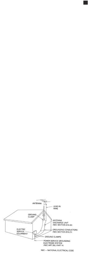
OutdoorAntennaGrounding–Ifanoutsideantennaorcablesystemisconnectedtothe unit,besuretheantennaorcablesystemisgroundedsoastoprovidesomeprotection againstvoltagesurgesandbuilt-upstaticcharges.Article810oftheNationalElectrical Code,ANSI/NFPA70,providesinformationwithregardtopropergroundingof the mastandsupportingstructure,groundingofthelead-inwiretoanantenna-discharge unit,size of grounding conductors,location of antenna-discharge unit,connection togroundingelectrodes,andrequirementsforthegroundingelectrode.
Lightning–For added protection for the unit during a lightning storm,or when the unitisleftunattendedandunusedforlongperiodsof time,unplugitfromthewall outletanddisconnecttheantennaorcablesystem.Thiswillpreventdamagedueto lightningandpower-linesurges.
Power Lines–An outside antenna system should not be located in the vicinity of overheadpowerlinesorotherelectriclightorpowercircuits,orwhereitcanfallonto suchpowerlinesorcircuits.Wheninstallinganoutsideantennasystem,extremecare should be taken to keep from touching such power lines or circuits as contact with themmightbefatal.
Overloading–Donotoverloadwalloutlets,extensioncords,orintegralconvenience receptaclesasthiscanresultinariskof fireorelectricshock.
ObjectandLiquidEntry–Neverpushobjectsofanykindintotheunitthroughopen- ingsastheymaytouchdangerousvoltagepointsorshort-outpartsthatcouldresult inafireorelectricshock.Neverspillliquidof anykindontheunit.
Servicing–Donotattempttoservicetheunityourselfasopeningorremovingcovers mayexposeyoutodangerousvoltageorotherhazards.Referallservicingtoqualified servicepersonnel.
DamageRequiringService–Unplugtheunitfromthewalloutletandreferservicing toqualifiedservicepersonnelunderthefollowingconditions:
Whenthepower-supplycordorplugisdamaged,
If liquidhasbeenspilled,orobjectshavefallenintotheunit, If theunithasbeenexposedtorainorwater,
Iftheunitdoesnotoperatenormallybyfollowingtheoperatinginstructions.Adjust only those controls that are covered by the operating instructions,as an improper adjustmentof othercontrolsmayresultindamageandwilloftenrequireextensive workbyaqualifiedtechniciantorestoretheunittoitsnormaloperation,
Iftheunithasbeendroppedordamagedinanyway,andgreatcareshouldbeexercised inhandling,andtheunitshouldbeexaminedbyqualifiedservicepersonnel.
When the unit exhibits a distinct change in performance–this indicates a need for service.
ReplacementParts–Whenreplacementpartsarerequired,besuretheservicetech- nician has used replacement parts specified by the manufacturer or have the same characteristics as the original part. Unauthorized substitutions may result in fire, electricshock,orotherhazards.
SafetyCheck–Uponcompletionof anyserviceorrepairstotheunit,asktheservice techniciantoperformsafetycheckstodeterminethattheunitisinproperoperation condition.
Wall or Ceiling Mounting–The unit should be mounted to a wall or ceiling only as recommendedbythemanufacturer.
Heat–The unit should be situated away from heat sources such as radiators, heat registers,stoves,orotherunits(includingamplifiers)thatproduceheat.
IMPORTANT SAFETY NOTE
Before connecting a new component such as the P-2000 to your audio or home theater systemit’salwaysgoodpracticetomakecertainthatallcomponentsareturnedoff,and preferably unplugged from their AC power source.Many modern electronics products feature automatic turn-on circuits that may be automatically activated during an installation, creating a potential for damage to electronic components and/or speakers. Such damage is not covered by product warranties andAtlantic Technology specifically disclaims responsibility for any such damage.
|
|
Precautions |
3 |
|
InstructionManual |
|
|
|
|
|
|
|
|
|
Precautions |
|
Do Not Open The Cabinet |
|
|
Verify The Line Voltage |
|
Therearenouserserviceablecomponentsinsidethisproduct.Openingthecabinetmay |
|
|
|
presentashockhazard,andanymodificationtotheproductwillvoidyourguarantee.If |
|
|
|
YournewP-2000hasbeenfactoryconfiguredfor120(+/-10%)voltAClines.Connect- |
|
water or any metal object,such as a paper clip,coin or a staple,accidentally falls inside |
|
|
ing the unit to a line voltage other than that for which it is intended can create a safety |
|
the unit, disconnect it from the AC power source immediately, and contact Atlantic |
|
|
and fire hazard,and may damage the unit.If you have any questions about the voltage |
|
Technology for further instructions. |
|
|
requirements for your specific model, or about the line voltage in your area, contact |
|
Recording Copyright |
|
|
Atlantic Technology before plugging the unit into a wall outlet. |
|
|
|
|
NOTE: It is always a good idea to avoid using any audio or video equipment on |
|
Recordingofcopyrightedmaterialforotherthanpersonaluseisillegalwithoutpermis- |
|
|
|
sion of the copyright holder. |
|
|
|
the same AC circuit as equipment with motors, such as air conditioners or refrig- |
|
|
|
|
|
Note to CATV system installer |
|
|
|
erators. This will lessen the possibility of power variation and electrical start-up |
|
|
|
|
noise affecting your sound system. |
|
This reminder is provided to call the CATV system installer’s attention to Article 820- |
|
|
|
40 of the NEC,ANSI/NFPA 70,which provides guidelines for proper grounding and,in |
|
|
|
Power Cord |
|
|
|
|
|
particular,specifies that the cable ground shall be connected to the grounding system |
|
|
|
TheremovablepowercordthatisshippedwiththeP-2000isspecificallydesignedtobe |
|
of the building,as close to the point of cable entry as practical. |
|
|
usedwiththisproduct.DONOTuseanyotherpowercord,asthatmayreducetheunit’s |
|
FCC Information for User |
|
|
performanceandpossiblycreateasafetyhazard.Inparticular,DONOTusestandardIEC |
|
|
|
|
typepowercordsdesignedforcomputersandotherbusinessequipmentproducts,asthey |
|
CAUTION:ANYchangesormodificationsnotexpresslyapprovedbythepartyrespon- |
|
|
haveathreeprongplugthatisnotmeantforusewiththeP-2000.Shouldthepowercord |
|
sible for compliance could void the user’s authority to operate the equipment. |
|
|
require replacement,use an identical type,or contactAtlantic Technology for service. |
|
NOTE:ThisequipmenthasbeentestedandfoundtocomplywiththelimitsforaClassB |
|
|
|
|
|
|
|
Handle the AC Power Cord Gently |
|
digitaldevice,pursuanttoPart15oftheFCCRules.Theselimitsaredesignedtoprovide |
|
|
WhendisconnectingthepowercordfromanACoutlet,alwayspulltheplug,neverpull |
|
reasonable protection against harmful interference in a residential installation. |
|
|
|
|
|
|
|
onthethecord.If youdonotintendtousetheP-2000foraconsiderablelengthof time, |
|
This equipment generates, uses and can radiate radio frequency energy and, if not |
|
|
disconnecttheplugfromtheACoutlet.If thepowercordisreplaced,makecertainthat |
|
installedandusedinaccordancewiththeinstructions,maycauseharmfulinterference |
|
|
it is of similar gauge.As with all electrical devices,do not run power cords under rugs |
|
toradiocommunications.However,thereisnoguaranteethatinterferencewillnotoccur |
|
|
or carpets or place heavy objects on them.Damaged power cords should be replaced |
|
in a particular installation. |
|
|
immediately with cords meeting factory specifications. |
|
Ifthisequipmentdoescauseharmfulinterferencetoradioortelevisionreception,which |
|
|
AC Fuse |
|
|
|
|
|
canbedeterminedbyturningtheequipmentoffandon,theuserisencouragedtotryto |
|
|
|
Thefuseislocatedinsidethechassisandisnotuserserviceable.Ifpowerdoesnotcome |
|
correct the interference by one or more of the following measures: |
|
|
on,contact your authorized service station. |
|
Reorientorrelocatethereceivingantenna. |
|
|
|
|
|
|
|
Wiring |
|
Increasetheseparationbetweentheequipmentandreceiver. |
|
|
Cables that are run inside of walls should have the appropriate markings to indicate |
|
Connect the equipment into an outlet on a circuit different from that to which the |
|
|
compliancewith,andlistingbytheUL,CSAorotherstandardsrequiredbytheUL,CSA, |
|
|
|
|
|
receiverisconnected. |
|
|
|
NECoryourlocalbuildingcode.Questionsaboutcablesinsideofwallsshouldbereferred |
|
|
|
|
|
|
|
|
|
to a qualified custom installer,or a licensed electrician or low-voltage contractor. |
|
Outdoor Antenna Installation |
|
|
Installation Location |
|
|
|
|
|
Safe Antenna and cable Connection |
|
|
|
To assure proper operation and to avoid the potential for safety hazards,place the unit |
|
|
|
|
on a firm and level surface capable of supporting its weight.When placing the unit on |
|
If anoutsideantennaorcablesystemisconnectedtotheequipment,besuretheantenna |
|
|
a shelf,be certain that the shelf and any mounting hardware can support the weight of |
|
or cable system is grounded so as to provide some protection against built up static |
|
|
the unit and any additional items in the equipment rack,or on the shelf. |
|
chargesandvoltagesurges.Section810ofthe |
|
|
When positioning the P-2000 in its final location, make certain that it has adequate |
|
NationalElectricalCode,ANSI/NFPA70 |
|
|
|
(inCanada,part1oftheCanadian |
|
|
|
ventilationonallsides,aswellasonthetopandbottom.Inparticular,itisagoodideato |
|
ElectricalCode)providesin- |
|
|
provideatleastthreeormoreinchesof spaceabovetheunitforaircirculation.DONOT |
|
formationwithrespect |
|
|
placeCDs,DVDs,videotapes,owner’smanuals,orotherpapersontopof,orbeneath,the |
|
to proper ground- |
|
|
unit,orin-betweenmultiplecomponentsinastack.Thiswillblockairflow,causingheat |
|
ingofthemastand |
|
|
build-up,degraded performance,and may create a possible fire hazard. |
|
supporting struc- |
|
|
If the unit is to be enclosed in a cabinet or rack, make certain there is adequate air |
|
ture, grounding |
|
|
|
of thelead-inwire |
|
|
|
circulationwithinthecabinetorrack.Sufficientventilationshouldbeprovidedsothat |
|
|
|
|
|
to an antenna dis- |
|
|
|
hot air may exit,and cool air may enter.In some instances,a small cooling fan may be |
|
|
|
|
|
chargeunit,sizeofgrounding |
|
|
|
required to insure adequate airflow through the cabinet.If you are in doubt as to the |
|
|
|
|
|
conductors, location of antenna dis- |
|
|
|
ventilation requirements for your specific installation, please contact us.Also, do not |
|
|
|
|
|
chargeunit,connectiontogroundingelectrodes |
|
|
|
place the P-2000 directly on a carpeted surface,as this will inhibit airflow underneath |
|
|
|
|
|
andrequirementsforthegroundingelectrode. |
|
|
|
as well as create a potential fire hazard. |
|
|
|
|
|
|
|
|
|
Avoidinstallationinhumidlocations,inextremelyhotorcoldlocations,orinareasthat |
|
Keep Antenna Clear of High Voltage Power Lines or Circuits |
|
|
are exposed to direct sunlight or space heating equipment. |
|
An outside antenna system should be located well away from power lines,electric light |
|
|
|
|
orpowercircuitsandwhereitwillnevercomeintocontactwiththesepowersourcesifit |
|
|
|
|
shouldhappentofall.Wheninstallinganoutsideantenna,extremecareshouldbetakento |
|
|
|
|
avoidtouchingpowerlines,circuitsorotherpowersourcesasthiscouldbefatal.Because |
|
|
|
|
of the hazards involved,antenna installation should be left to a professional. |
|
|
|
|
|
|
|

4 |
Table of Contents |
P-20007.1ChannelPreamp/Processor/Tuner
TableofContents
2 |
Please Read First |
31 |
Surround Data Format Lock |
|
5 |
P-2000 Features |
31 |
Bypass Setting |
|
6 |
Unpacking |
32 |
Tuner Operation |
|
6 |
Accessories |
33 |
Recording a Source |
|
6 |
P-2000 Front Panel |
33 |
Tone Controls |
|
8 |
P-2000 Rear Panel |
33 |
Night Mode |
|
9 |
Front Panel and On Screen Display (OSD) |
33 |
Channel Trim |
|
10 |
Remote Control |
34 |
Theater Compensation |
|
12 |
Surround Format Information |
35 |
Multi-channel Source Playback |
|
12 |
Dolby Digital |
|||
35 |
Analog Bass Management |
|||
12 |
Dolby Digital Surround EX |
|||
35 |
Sleep Timer |
|||
12 |
Dolby Pro Logic II |
|||
35 |
Setting the Front Panel Display Brightness |
|||
12 |
DTS |
|||
36 |
Setting the On Screen Display (OSD) Time Out |
|||
13 |
DTS-ES |
|||
36 |
Multi-Zone Remote Operation |
|||
13 |
DTS NEO:6 |
|||
37 |
Remote Control Setup and Operation |
|||
13 |
Cirrus Extra Surround |
37 |
Battery Installation |
|
13 |
Stereo |
37 |
Setup Using Preprogrammed Codes |
|
13 |
Additional Information |
38 |
Operation |
|
13 |
Connecting Your P-2000 |
39 |
Source Selection Buttons |
|
19 |
ConnectingAudio Components |
|||
39 |
Backlighting |
|||
19 |
CD Player |
|||
39 |
Volume Control Punch Through |
|||
19 |
Audio Recorder |
|||
39 |
Macro Buttons |
|||
19 |
ConnectingVideo Components |
|||
40 |
Example of Programming a Macro Sequence: |
|||
19 |
DVD Player |
|||
40 |
Learning Commands fromAnother Remote |
|||
20 |
Video Recorder |
|||
40 |
Learning a New Command |
|||
20 |
Video Display |
|||
41 |
Setup Codes |
|||
20 |
Satellite Tuner or Television |
44 |
Care and Maintenance |
|
20 |
FMAntenna |
44 |
Cleaning |
|
21 |
AMAntenna |
44 |
WhenYouAreAway |
|
21 |
ExternalAmplifier |
44 |
Troubleshooting |
|
21 |
Second Zone |
45 |
System Reset |
|
21 |
Power Control Connections |
46 |
Specifications |
21Remote Control
21Power Connection
22System Setup
22Navigating the Setup Menus
23Input Setup and Selection
24Speaker Configuration
24 Speaker Placement
27Channel Calibration
28System Configuration
28 Setting The Speaker Distance Delays
28Dolby Pro Logic II (PLII) Music Parameter
29Multi-zone
30Operation
30 |
Power |
30 |
Selecting a Source |
30Selecting a Source Input
30Volume Control
31Muting theVolume
31 Changing the Surround Mode
Record your P-2000’s serial number and date of purchase here. The serial number is found on the back panel.
Serial Number
Date of Purchase
The contents of this manual are Copyright © 2002 by Atlantic Technology International, Corp.,andmaynotbeduplicatedorreproducedbyanymeans,whetherphysical,electronic orotherwisewithoutpriorwrittenconsentfromAtlanticTechnologyInternational,Corp.
AtlanticTechnologyandtheAtlanticTechnologylogoareregisteredtrademarksofAtlantic
Technology Interantional,Corp.
Specificationsarethoseineffectatthetimeofprinting.AtlanticTechnologyInterantional, Corp.reserves the right to change specifications or designs at any time without notice without obligation to modify existing units.

P-2000 Features |
5 |
InstructionManual
P-20007.1Channel
Preamp/Processor/Tuner
ThankyouforpurchasingtheAtlanticTechnologyP-2000Preamp/Processor/ Tuner.TheP-2000combinesadvancedtechnology,superiorcomponentparts, andverysophisticatedsoftwarewithaclean,user-friendlystyle,impeccable audioperformanceandleadingedgecapabilities,makingittheperfectfoundationforanymusicorsurroundsoundsystem.
InordertoreceivethemaximumenjoymentfromyourP-2000,pleasetake afewminutestoreadthismanual.Itcontainsallofthenecessaryinformationtosetup,connectanduseyournewunit.Thisimportantinformation willhelpyoumakecertainthattheunitisproperlyconfiguredforoperation withtherestoftheequipmentinyoursystem.Thisbriefinvestmentoftime willprovidemajordividendsbymakingcertainthatyournewcomponentis properlyinstalledandoptimizedforthespecificsofyourinstallation.
If you have any questions about this product,its installation or operation, please contact us via e-mail at customerservice@atlantictechnology.com or via telephone at 781-762-6300 during standard Eastern Time business hours.
Important Note: The P-2000 is shipped from the factory in the following default mode:
P-2000 Features
YournewPreamp/Processor/Tunerisanadvancedhighperformanceaudio/ videocomponent.TheP-2000providesmaximumsystemconnectionflex- ibility with advanced surround processing technologies assuring compat- ibilitywiththewidestrangeofsourcematerial.TheP-2000features:
DolbyDigital®andDolbyDigitalEX¨Decoding*
DolbyDigitaldecodingdelivers5.1discretechannelsfromDolbyDigital encodedDVD,satellite,cableandHDTVsources,whilethelatestDolby DigitalEXprocessaddsanadditionalmatrixedrearsurroundchannel fortheultimatehometheaterexperience.
DolbyProLogic®II*
The latest surround technology from Dolby Laboratory delivers enhancedsurroundchannelperformanceanda5.1channelsurround soundfieldfromregularDolbySurroundorstandardstereosources.
DTS®,DTS-ES®andNEO:6Decoding**
ThefullsuiteofDTS(DigitalTheaterSystems)surroundsounddecod- ingandprocessingisavailabletoprovidemulti-channelreproduction from virtually any analog source as well as DTS digitally encoded programs.
CirrusExtraSurround®
TheP-2000isamongthefirstsurroundproductstoofferCirrusExtra Surround which provides enjoyable and involving 6.1 or 7.1 channel reproductionfromdigitalandanalogsources.
Output Configuration |
7.1 |
L/R, Center, Surround Loudspeaker Size |
Small |
All Crossovers |
100Hz |
After reading the rest of this manual and determining how your system should be set up, please refer to pages 24-26 if you need to change these settings.
If your system will be operated in less than a 7.1 channel configuration, some Digital Signal Processing (DSP) modes described in this manual will not be available to you.
6DigitalInputs(2coaxial,4optical)
Eachdigitalinputcanbeassignedtoaspecificsourceunit,providing comprehensivesystemconnectivity.
2DigitalOutputs(1coaxial,1optical)
Forusewithdigitalrecordersordistributionsystems.
HighBandwidthComponentVideoSwitching
HDTV compatible component switching for use with digital set top boxesandprogressivescanDVDplayers.
5CompositeandS-VideoInputs
High-qualityvideocircuitryforconnectiontoyourvideosources.
9AnalogAudioInputswithBypassCapability
All analog audio inputs may be switched to Bypass mode for pure analogsound,orusedwiththelatestsurroundprocessingforfurther enjoyment.
VideoOutputConversion
Video inputs are automatically converted from S-Video to composite whenusingtheseoutputs.ConversionfromcompositetoS-Videoalso takesplace,howevertheremaybesomelimiteddegradationofthesignal andwedonotrecommenditsuse.
* Manufactured under license from Dolby Laboratories.
**Manufactured under license from Digital Theater Systems,Inc.US Pat.No.5,451,942 and other worldwide patents issues and pending.
“Dolby,”“Pro Logic”and the double-D symbol are trademarks of Dolby Laboratories. ©1992-1997 Dolby Laboratories,Inc.All rights reserved.
“DTS”and“DTS Digital Surround”are trademarks of Digital Theater Systems,Inc. © 1996 Digital Theater Systems,Inc.All rights reserved.
“Extra Surround”is a trademark of Cirrus Logic Inc.

6 |
P-2000 Front Panel |
|
P-20007.1ChannelPreamp/Processor/Tuner |
HighperformanceAM/FM/FMStereotunerwith32presets |
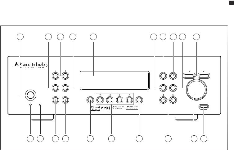
P-2000 Front Panel |
||
Audiophilequalitypreamplifierstages |
1 Standby power button (see page 22, 30) |
||
Provideexceptionalperformanceforcriticalmusiclistening. |
|||
|
WhenthemainPOWERswitchontherearpanelisintheONposition, |
||
5.1Multi-channelanaloginputs |
|
||
|
pressing this button turns the unit on.The yellow STANDBY/MUTE |
||
Connectthe5.1-channeloutputsfromaDVD-AorSACDmulti-channel |
|
||
|
indicatorlightgoesout. |
||
playerorothermulti-channelaudioformatstotheseinputs. |
|
||
|
Pressing this button again returns the unit to standby mode. The |
||
IndependentMulti-roomSystem |
|
||
|
STANDBY/MUTEindicatorlightilluminates. |
||
When properly connected, a second stereo source may be sent to a |
|
||
|
InSTANDBYMODE,theFRONTPANELDISPLAYisturnedoff,control |
||
remoteroom,completewithremotevolumecontrol,sourceselection |
|
||
|
functionsaredisabled,andalloutputstothemainzoneareturnedoff. |
||
andtunercontrol.Alowvoltagetriggeroutputforthesecondzoneallows |
|
||
|
However,outputstotheremotezoneremainactiveandavailable. |
||
asecondamplifiertoturnonandoffindependentlyofthemainroom. |
|
||
|
|
||
Thissystemmayalsobeusedtorecordaninputsourcethatisdifferent |
2 FM MODE button (see page 32) |
||
fromtheonebeingusedinthemainroom. |
|
TogglestheFMTunerbetweenMonoandStereomode.Theletters“M” |
|
|
|
||
2Lowvoltagetriggers |
|
or“S” appear next to the Tuner Preset number in the FRONT PANEL |
|
One trigger provides automatic turn on/off of compatible power |
|
DISPLAYtoindicatewhichmodethetunerisoperatingin. |
|
amplifierssuchastheAtlanticTechnologyA-2000poweramplifieror |
3 |
TUNE buttons (see page 32) |
|
relay-controlledproductssuchasprojectionscreens,blindsandlighting |
|||
|
The and buttonsadjustthetunedfrequencydownorupwhenTuner |
||
systems.The second trigger provides on/off control for an amplifier |
|
||
|
isselectedastheinputsource. |
||
usedwiththemulti-roomsystem. |
|
||
4 FM/AM button (see page 32) |
|||
Unpacking |
|||
|
Toggles betweenAM and FM radio bands.Pressing this button when |
||
The carton and packing materials used in shipping your new Preamp/ |
|
listeningtoanyothersourceautomaticallychangestheunit’sinputsource |
|
|
totheTunerandthelaststationlistenedto. |
||
Processor were specially designed to cushion it from the shocks and |
5 |
FRONT PANEL DISPLAY (see page 9) |
|
vibration of shipping.We strongly suggest that you save the carton and |
|||
packingmaterialstouseifyoumove,oriftheuniteverneedstobeshipped |
|
Indicates program source,DSP mode,tuner preset and/or frequency, |
|
|
digitalinput,volumelevel,andotherPreamp/Processor/Tuneroperat- |
||
foranyreason. |
|
||
|
ing information.Also displays menu selections. May be dimmed for |
||
Tominimizethesizeofthecartoninstorage,youmaywishtoopenthetop |
|
||
|
darkenedroomoperation. |
||
andbottomflapsandfoldthecartonflat.Othercardboardinsertsmaybe |
|
||
6 |
TEST TONE button (see page 27) |
||
storedinthesamemanner.Packingmaterialsthatcannotbecollapsedshould |
|||
besavedalongwiththecartoninaplasticbag. |
|
Pressthisbuttontousetheinternalaudiotestsignalgeneratortoadjust |
|
Although not particularly heavy,the P-2000 has several front mounted |
|
the output level for each channel.As this signal circulates through the |
|
|
channels, press the < or > Navigation buttons to make precise level |
||
controlsandmanyrearpanelconnectors,sobecarefulwhenliftingand |
|
||
|
adjustments. |
||
placingitsoasnottocausedamage. |
|
||
|
|
||
Accessories |
7 DIGITAL SELECT button (see page 30) |
||
|
Pressthisbuttontoselectadigitalinput.Eachpressofthebuttonscrolls |
||
AfterunpackingtheP-2000,pleasecheckthatthefollowingaccessoriesare |
|
tothenextinput,asshownontheFRONTPANELDISPLAYortheON |
|
|
SCREEN DISPLAY.When ANALOG is shown, the L/R analog input |
||
inthebox: |
|
||
|
associatedwiththeinputinuseisselected. |
||
|
|
||
RemoteControlwithBatteries |
8 STEREO BYPASS button (see page 31) |
||
ACPowerCord |
|||
|
Defeats the DSP processing section and provides an unaltered, full- |
||
FMWireAntenna |
|
bandwidth stereo signal to the Left and Right channel outputs on the |
|
AMLoopAntenna |
|
rear panel.However,the subwoofer DSP crossover remains active and |
|
|
bassfrequenciesareavailableatthesubwooferoutputshouldyouwishto |
||
Owner’sManual |
|
||
|
augmentyourfrontLRspeaker’slowfrequencyperformance.Theword |
||
If any of the above is missing from your shipment,please contactAtlantic |
|
BYPASS appears in the FRONT PANEL DISPLAY.Pressing the button |
|
Technologyimmediately. |
|
againreturnstheunittothepreviouslyselectedDSPmode. |
|
9 TRIM button (see page 33)
Pressthisbuttontoadjusttheoutputofanindividualchannelaboveor belowthemastervolumelevelsettingfrom-15dBto+10dB.Pressthe <or>Navigationbuttonstoadjustthelevelforthechannelindicated
P-2000 Front Panel |
7 |
InstructionManual
P-2000 Front Panel
1 |
2 |
3 |
4 |
5 |
6 |
7 |
8 |
9 |
10 |
|
|
|
|
|
|
|
|
|
|
|
|
|
|
|
|
|
|
|
11 |
12 |
13 |
14 |
15 |
16 |
17 |
18 |
19 |
20 |
intheFRONTPANELDISPLAYortheONSCREENDISPLAYandthen pressthebuttonagaintoselectthenextchannelinsequence.
10 SOURCE buttons (see page 30)
Presseitherofthesebuttonstotogglethroughtheinputsourcesavailable andselecttheoneyouwishtolistento.
11 On/Standby/Mute indicator (see page 22, 30)
LightstoindicatewhentheunitisinStandbymodeandgoesoutwhen thepreamp/processorisactive.Alsoflashestoindicatewhenthemain systemvolumeismuted.
12 MULTI indicator LED (see page 29, 36)
Lightstoindicatethatthesecondzone(Zone2)isactive.Notethatthis lightwillremainlitevenwhentheotherindicatorsareoff,aslongasthe secondzoneisactive.
13 PRESET SCAN button (see page 32)
Pressing this button scans the receivable AM or FM stations stored in the tuner’s preset memory, stopping briefly (5 seconds) at each. Pressing it again stops the scan at the preset indicated in the FRONT PANELDISPLAY.Theunit’sinputsourceautomaticallychangestoTuner whenthisbuttonispressed.
14 MEMORY button (see page 32)
PressingthisbuttonwhenFMorAMisselectedastheinputsourcestores thecurrentstationfrequencyintooneofthepresets.Youcanpresetup to32randomlymixedAMorFMstations.
15 MENU button (see page 22)
Enters the Menu mode and displays the menu options on the FRONT PANELDISPLAYandtheONSCREENDISPLAY(OSD).Pressthebutton againtoexittheMenumode.
16 Navigation buttons (see page 22)
WheninMenumode,usethesebuttonstonavigatethroughthemenu optionsdisplayedontheFRONTPANELDISPLAYortheONSCREEN DISPLAY(OSD).Thesebuttonsarealsousedtochangeoptionsorsettingswithsomeofthefrontpanelcontrols.
17 SELECT button (see page 22)
WheninMenumode,selectsthemenuoptionsdisplayedontheFRONT PANELDISPLAYortheONSCREENDISPLAY(OSD).
18 SURR MODE buttons (see page 31)
Pressthesebuttonstoselectamongthevarioussurroundmodespro- videdbytheP-2000.TheModesavailabledependonyoursystem’ssetup configurationandthechoseninputsource.
19 VOLUME control (see page 30)
Adjuststhevolumelevelforthemainzoneonly.Remotezone(Zone2) isnotaffectedbythiscontrol.
20 MUTE button (see page 31)
MutestheMainSystemvolume.TheSTANDBY/MUTEindicatorflashes. Pressingthebuttonagainreturnstheunittothepreviousvolumesetting. TheSTANDBY/MUTEindicatorgoesout.
8 |
P-2000 Rear Panel |
|
|
|
|
|
|
|
|
|
|
|
|
|
|
|
|
|
|
||
|
|
|
|
|
|
|
|
|
|
|
|
|
|
|
|
|
|
|
|
P-20007.1ChannelPreamp/Processor/Tuner |
|
P-2000 Rear Panel |
|
|
|
|
|
|
|
|
|
|
|
|
|
|
|
|
|
||||
1 |
2 |
3 |
|
|
4 |
5 |
|
|
6 |
|
7 |
|
|
8 |
|
9 |
10 |
|
|
11 |
|
|
|
|
|
|
|
|
|
|
|
|
|
|
|
|
|
|
|
|
|
||
|
|
|
|
|
|
|
|
|
|
|
|
|
|
|
|
|
|
|
|||
|
|
|
|
|
|
|
|
|
|
|
|
|
|
|
|
|
|
|
|
||
|
|
|
|
|
|
|
|
|
|
|
|
|
|
|
|
|
|
|
|
|
|
|
|
|
|
|
|
|
|
|
|
|
|
|
|
|
|
|
|
|
|
|
|
|
|
|
|
|
|
|
|
|
|
|
|
|
|
|
|
|
|
|
|||
|
|
|
|
|
|
|
|
|
|
|
|
|
|
|
|
|
|
|
|||
|
|
|
|
|
|
|
|
|
|
|
|
|
|
|
|
|
|
|
|
|
|
|
|
|
|
|
|
|
|
|
|
|
|
|
|
|
|
|
|
|
|
|
|
|
|
|
|
|
|
|
|
|
|
|
|
|
|
|
|
|
|
|
|
|
|
|
|
|
|
|
|
|
|
|
|
|
|
|
|
|
|
|
|
||||
|
|
|
|
|
|
|
|
|
|
|
|
|
|
|
|
|
|
|
|||
|
|
|
|
|
|
|
|
|
|
|
|
|
|
|
|
|
|
|
|
|
|
|
|
|
|
|
|
|
|
|
|
|
|
|
|
|
|
||||||
|
|
|
|
|
|
|
|
|
|
|
|
|
|
|
|
|
|
|
|||
|
|
|
|
|
|
|
|
|
|||||||||||||
|
|
|
|
|
|
|
|
|
|
|
|
|
|
|
|
|
|
|
|||
|
|
|
|
|
|
|
|
|
|
|
|
|
|
|
|
|
|
|
|||
|
|
|
|
|
|
|
|
|
|
|
|
|
|
|
|
|
|||||
|
|
|
|
|
|
|
|
|
|
|
|
|
|
|
|
|
|
|
|
||
|
|
|
|
|
|
|
|
|
|
|
|
|
|
|
|
|
|
|
|||
|
|
|
|
|
|
|
|
|
|
|
|
|
|
|
|
|
|
|
|||
|
|
|
|
|
|
|
|
|
|
|
|
|
|
|
|
|
|
|
|
||
|
|
|
|
|
|
|
|
|
|
|
|
|
|
|
|
|
|
||||
|
|
|
|
|
|
|
|
|
|
|
|
|
|
|
|
|
|
|
|
|
|
|
|
|
|
|
|
|
|
|
|
|
|
|
|
|
|
|
|
|
|
||
|
|
|
|
|
|
|
|
|
|
|
|
|
|
|
|
|
|
|
|
|
|
|
|
|
|
|
|
|
|
|
|
|
|
|
|
|
|
|
|
||||
|
|
|
|
|
|
|
|
|
|
|
|
|
|
|
|
|
|
|
|
|
|
|
|
|
|
|
|
|
|
|
|
|
|
|
|
|
|
|
|
|
|
||
|
|
|
|
|
|
|
|
|
|
|
|
|
|
|
|
|
|||||
|
|
|
|
|
|
|
|
|
|
|
|
|
|
|
|
|
|
|
|
|
|
|
|
12 |
|
|
|
|
13 |
|
|
14 |
15 |
16 |
|
17 |
18 |
19 |
|
20 |
21 |
||
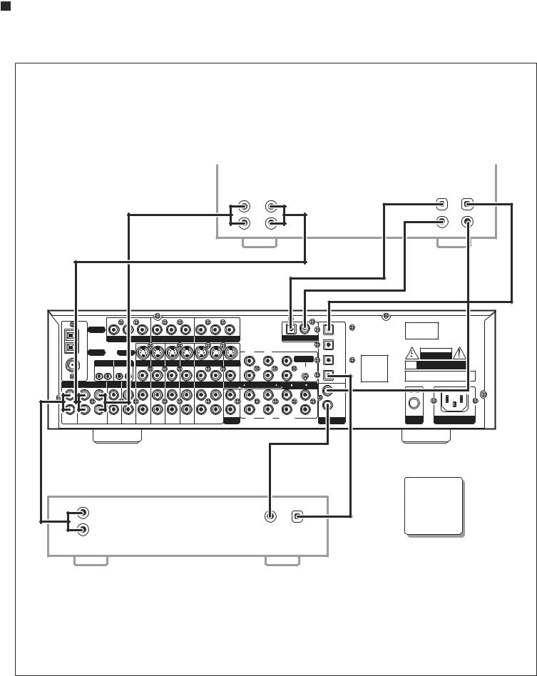
P-2000 Rear Panel
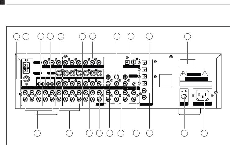
Below is a brief explanation of the connections and switches found on the P-2000rearpanel.Beforeconnectinganyaudioorvideocomponentstothe unit,familiarizeyourselfwiththetypeandlocationofconnectorsavailable.
1 FM Antenna terminal (see page 20)
UsetoconnectthesuppliedFMantennaoranexternal75Ωantenna.
2 AM Antenna terminals (see page 20)
ConnectthesuppliedAMloopantennaoranexternalAMantennato theseterminals.
3 Remote Trigger jacks (see page 21)
UsetheMAINandZONEDCTRIGGERjackstocontrolexternaldevices (suchasapoweramplifier)witha3-32VDCtriggerinput.Thedevice connectedtotheMAINjackwillbeactivatedwhentheP-2000isturned on and should be used for connections to power amplifiers or other devices in the main room.The device connected to the ZONE trigger willonlybeactivatedwhentheMulti-zonesystemisturnedon.Connect ittotheamplifierorotherdevicesusedinthesecondzone.
4 Remote Control jacks (see page 21)
UsetheMAINandZONEEXTREMOTEjackstoconnectexternalIR sensorstotheP-2000.Whentheunitisinstalledbehinddoorsorwhere itisnototherwisevisibletothehandheldremote,connectanoptional, external sensor to the MAIN jack.To control the Multi-room system fromaremotelocation,connectanoptionalremotesensorinthesecond roomtotheZONEEXTREMOTEjack.
5 Component Video Input jacks (see page 19-20)
Use these two sets of jacks to connect devices with component video outputssuchasaDVDplayerorHDTVtuner.
6 S-Video jacks (see page 19-20)
Connect the S-Video output of sources to the appropriate input jacks. ConnecttheVCR-OUTjacktotheinputof aVCRorotherrecorderand connecttheOUTjacktoanS-Videoinputonyourvideodisplaydevice.
7 Component Video Output jacks (see page 19-20)
Usethesejackstosupplycomponentvideooutputtoanexternalmonitor thatacceptscomponentvideosignals.(NotethattheOSDisnotavailable on the Component Video Output as it could potentially degrade thevideosignal.)
8 5.1 Channel Input jacks (see page 21)
Connect the multi-channel signal from the analog audio outputs of a devicesuchasaDVD,DVD-AorSACDtothesejacks.
9 Digital Outputs (see page 20)
Use the coaxial and optical digital outputs to connect the preamp/ processortoadevicesuchasCDrecorder,DATrecorder,orothersimilar devicethatacceptsadigitalaudioinput.Thesejacksautomaticallyoutput thesignalfromwhicheverdigitalinputhasbeenselectedforlistening.
10 Optical Digital Inputs (see page 19-20)
Usetheseinputstoconnecttheopticaldigitalaudiosignaloutputfrom such digital devices as CD,DVD or LD players.These inputs are fully assignable.

Front Panel and On Screen Display (OSD) |
9 |
InstructionManual |
|
11 Product Serial Number |
P-2000 Front Panel and On Screen Display |
|
Writethisnumberinthespaceprovidedonpage4of thismanualfor |
|
|
futurereference. |
|
|
Example of Front Panel |
||
12 Audio Source Input jacks (see page 19-20) |
||
Display when an input |
||
UsetheseinputsforconnectiontoanalogaudiosourcessuchasaCDplayer. |
source is selected. |
|
|
||
Onein/outtapepathisprovidedforconnectiontoanaudiorecorder. |
|
|
13 Video Source Input jacks (see page 19-20) |
|
|
Usetheseinputsforconnectiontothecompositevideoandanalogaudio |
Example of On Screen |
|
outputfromsourcessuchasaDVDorLDplayer,satellitereceiver,cable |
||
box,PVRorothervideosource.NotethatwhentheComponentVideo |
Display when an input |
|
source is selected. |
||
inputsareused,connecttheanalogaudiooutputsof thesourcetothe |
|
|
DVDorVideo1jacks,asappropriate. |
|
|
14 VCR jacks (see page 20) |
|
|
UsetheseaudioinputandoutputjackstoconnectaVCRtotheP-2000. |
|
|
15 Multi-zone Output jacks (see page 21) |
|
|
Usethesejackstosupplytheanalogstereoaudiooutputtoanoptional |
|
|
audioamplifierusedtopowerspeakersintheremotezone. |
|
|
16 Composite Monitor Output jack (see page 20) |
Example of Front Panel |
|
Connect this output to the composite video input of your monitor or |
Display when the Main |
|
othervideodisplaydevice. |
Menu is selected. |
|
|
||
17 Amplifier Output jacks (see page 21) |
|
|
UsethesevenaudiochanneloutputjackstoconnecttheP-2000toan |
|
|
external power amplifier.The eighth jack supplies the low frequency |
Example of On Screen |
|
outputtoapoweredsubwooferorexternalsubwooferamplifier. |
||
|
Display when the Main |
|
18 5.1 Input Bass Management Control (see page 34) |
Menu is selected. |
|
|
||
SettingthisswitchintheONpositionactivatesadedicated80HzHigh |
|
|
PassFilterforthe5.1channeldirectinput,exceptthesubwoofer.Thebass |
|
|
signalsfromthe5satellitechannelsof thisinputwillbesummedand |
|
|
sentontothesubwooferoutputatalltimes,sothisswitchonlyaffects |
|
|
whetherornotthebasssignalsaresentontothesatellitesaswell.Set- |
|
|
tingtheswitchinthedownpositionturnsoff theHighPassFilterand |
|
|
sendsfull-rangeaudiotoallsatellitechannels.ThisBassManagement |
|
|
Controlistotallyseparatefromthe“normal”DSPBassManagementset |
|
|
upusingthefrontpanelorremotecontrol. |
|
|
|
19 Coaxial Digital Input jacks (see page 19-20)
Usetheseinputstoconnectthecoaxialdigitalaudiosignaloutputfrom such digital devices as CD,DVD or LD players.These inputs are fully assignable.
20 Main Power switch (see page 22)
Turns the current to the P-2000 On or Off.Setting this button to the Onposition(pushedin)suppliespowertotheunit,enablinguseofthe StandbyPowerbuttononthefrontpanel.WhentheMainPowerswitch is in the Off position,current is cut off to the unit.This switch can be usedasaVacationSwitchtoshutoff themainpowertotheunitwhen youwillbegoneforalongperiodoftime.
21 AC Input (see page 21)
UsetoconnectthesuppliedACpowercord(seePrecautionsonpage2).
Front Panel and On Screen Display (OSD)
The FRONT PANEL DISPLAY and ON SCREEN DISPLAY (OSD) provide visual feedback of the current settings, surround modes and configuration menus of the unit. Information is constantly displayed on the front panel whenever the P-2000 is turned on.To view the OSD,the unit must beconnectedtoyourdisplaydeviceusingeitherthecompositeorS-Video MONITOR OUT jacks.The OSD will not operate through the component videooutputsoftheP-2000.However,theOSDoutputwillappearatboththe compositeandS-Videojacksregardlessofthetypeofsourceinuse.
Theinformationpresentedonthefrontpanelisidenticaltothatshownon theOSD,allowingyoutoperformspeakersettings,setupyourinputsources, setthelisteningmodes,andmuchmore.YoucanchoosehowlongtheOSD remainsonthescreenintheOSDsetupmenuandshouldyouchoosethe0 timeoption,theOSDwillnotappearonscreenatall.

10 |
Remote Control |
|
|
|
|
|
|
|
|
|
|
|
|
|
|
|
|
|
|
|
P-20007.1ChannelPreamp/Processor/Tuner |
P-2000 Remote Control |
|
|
|
|
Remote Control |
|||||
|
|
|
|
|
|
|
|
|
The P-2000 Universal Learning Remote Control duplicates every function |
|
|
|
|
|
|
|
|
|
|
availablefromfrontpanelofthepreamp/processorandmore.Itisdesigned |
|
|
|
|
|
|
|
|
|
|
to access all the configuration and operating menus of the P-2000.These |
|
|
|
|
|
|
|
|
|
|
are displayed on the FRONT PANEL DISPLAY,as well as the ON SCREEN |
|
|
|
|
|
|
|
|
|
|
DISPLAY (OSD).The Remote Control contains an extensive library of IR |
|
|
|
|
|
|
|
|
|
|
codesandmaybeprogrammedtooperateawiderangeofotheraudioand |
|
|
|
|
|
|
|
|
|
|
videocomponents.Additionally,youcanteachtheremotetocontrolother |
|
|
|
|
|
|
|
|
|
|
audio/video units not included in the unit’s built-in memory by entering |
|
|
|
|
|
|
|
|
|
|
theirparticulardevicecodes(seepage39). |
|
1 |
|
|
|
|
|
|
|
|
Many of the buttons on the Remote Control serve multiple functions, |
|
|
|
|
|
|
depending on the source device being controlled.The list below describes |
|||||
|
|
|
|
|
eachbutton’smainfunctions.Foracompletedescriptionoftheiruse,please |
|||||
|
|
|
|
|
|
|
|
|
||
|
|
|
|
|
|
|
|
refertothesectiontitled“RemoteControlSetupandOperation”. |
||
|
|
|
|
|
|
|
|
|
||
|
|
|
|
|
|
|
||||
2 |
|
|
|
|
|
|
|
|
1 |
Status LED Indicator (see page 37) |
|
|
|
|
|
|
|
|
|
||
|
|
|
|
|
|
|
|
|
|
IndicateswhentheremotecontrolisinProgrammingorLearningmode |
3 |
|
|
|
|
|
|
|
|
andflashestoindicatesuccessorfailureofthesefunctions. |
|
|
|
|
|
|
|
|
|
|||
4 |
|
|
|
|
|
14 |
|
2 |
Source Selection buttons (see page 30) |
|
|
|
|
|
|
|
|
|
|||
5 |
|
|
|
|
|
|
15 |
|
|
WhentheP-2000isinStandbymode,pressingoneofthesebuttonsturns |
6 |
|
|
|
|
|
|
|
|
theunitonandselectsthatsourceasthecurrentinput. |
|
|
|
|
|
|
|
|
|
|
|
|
|
|
|
|
|
|
|
16 |
|
|
If the P-2000 is already on,pressing one of these buttons selects that |
|
|
|
|
|
|
|
|
|
sourceasthenewinput. |
|
|
|
|
|
|
|
|
|
|
|
|
|
|
|
|
|
|
|
|
|
|
|
7 |
|
|
|
|
|
|
17 |
|
|
Inbothcases,onceproperlyprogrammed,theremotecontrolalsooper- |
|
|
|
|
|
|
|
|
atesthesourcedeviceselected. |
||
|
|
|
|
|
|
|
|
|
|
|
|
|
|
|
|
|
|
|
|
|
|
|
|
|
|
|
|
|
|
|
|
TheAUDbuttonsetstheRemotetocontroltheP-2000. |
|
|
|
|
|
|
|
|
|
|
|
|
|
|
|
|
|
|
|
|
|
|
|
|
|
|
|
|
|
|
|
|
The Source button selected will light whenever you push one of the |
|
|
|
|
|
|
|
18 |
|
|
|
|
|
|
|
|
|
|
|
Remote’s function buttons to indicate that you have sent a command |
||
|
|
|
|
|
|
|
|
|
|
|
8 |
|
|
|
|
|
|
19 |
|
|
tothatcomponent.If thecommandyouhavepressedisonethatisnot |
|
|
|
|
|
|
|
available on that type of unit (i.e.P SCAN on a CD player) the source |
|||
|
|
|
|
|
|
20 |
|
|
||
9 |
|
|
|
|
buttonwillnotlight,althoughyouhavepressedthatbutton. |
|||||
|
|
|
|
|
|
|
|
|||
10 |
|
|
|
|
21 |
|
3 POWER button (see page 27, 30) |
|||
|
|
|
|
|
|
|
22 |
|||
|
|
|
|
|
|
|
|
ReturnstheP-2000tostandbymodewhentheunitison. |
||
11 |
|
|
|
|
|
|
23 |
|
|
|
|
|
|
|
|
|
|
24 |
4 |
MUTE button (see page 31) |
|
12 |
|
|
|
|
|
|
25 |
|
||
13 |
|
|
|
|
|
|
|
|
MutesthemainvolumeoftheP-2000.Doesnotmutethesecondzone. |
|
|
|
|
|
|
|
|
26 |
|
5 |
Multi-zone button (see page 36) |
|
|
|
|
|
|
|
|
|
|
PresstheMULTIbuttontocallupandcyclethroughtheMulti-zonemenu |
|
|
|
|
|
|
|
|
|
|
optionsontheFRONTPANELDISPLAYandtheOSD,ifactive. |
|
|
|
|
|
|
|
|
|
6 TEST button (see page 27) |
|
|
|
|
|
|
|
|
|
|
|
Outputsanaudiotesttoneforcalibratingandsettingthespeakerlevels. |
|
|
|
|
|
|
|
|
|
|
Pressingthebuttonagainrestorestheaudiooutputfromthepreviously |
|
|
|
|
|
|
|
|
|
|
selectedinputsource. |
|
|
|
|
|
|
|
|
|
7 TRIM button (see page 33) |
|
|
|
|
|
|
|
|
|
|
|
ActivatestheChannelTrimfunction.Pressingthebuttoncyclesthrough |
|
|
|
|
|
|
|
|
|
|
all the channels individually for trim adjustment up to 10dB above or |
|
|
|
|
|
|
|
|
|
|
15dBbelowthemastervolumesetting,in1dBsteps.(1dBisthesmallest |
|
|
|
|
|
|
|
|
|
|
amountofsoundchangereadilyperceptibletohumanhearing.) |
Remote Control |
11 |
InstructionManual
8 Numeric Keypad buttons (see page 32) |
18 Auxiliary Input buttons (see page 30) |
Usethesebuttonsforcontrolfunctionsrequiringyoutoenternumbers. For numerals over 10,press the 10+ button for every multiple of ten, followedbyaseconddigit(0-9).
9Theater Compensation button (see page 34)
TheT.COMPbuttontogglesTheaterCompensationprocessingonand off.
10 Surround/Data Format buttons (see page 31)
Press the 2,DTS,CR SURR or STEREO button once to select a surroundprocessingformat.
Press the same button again to cycle through the various processing modesavailableforthatselectedformat.
Pressing and holding the button for five (5) seconds calls up the Data Formatmenu.
11 DIGITAL button (see page 30)
Cyclesbetweenthesixdigitalinputsandtheanaloginput(fortheselected source)ontheP-2000.TheselectedinputisshownontheFRONTPANEL DISPLAYandtheOSD,ifactive.
12 NIGHT button (see page 33)
Cyclesthroughtheavailabledynamicrangecompressionmodes.
13 Macro Control buttons (see page 39)
The M1,M2,M3 and M4 buttons are used to send IR macros,which consistofapreprogrammedsequencesofIRcommandsthatyouhave previouslyenteredintheremote.
14 Tuning and Volume buttons (see page 30, 32, 39)
Use the  and
and  CH/TUNE buttons to adjust the P-2000 tuner’s frequency down or up whenAUD is selected as the input source.These buttonsalsooperatetheTunerorchangechannelsofotherdevicesthat havebeenselectedasthecurrentsource.
Usethe and
and VOLbuttonstoadjustthevolumeoftheP-2000from –80dBto+10dB.Thesebuttonsalsooperatethevolumecontrolofother devicesthathavebeenselectedasthecurrentsource.
15 MENU button (see page 22)
CallsuptheMainMenuontheFRONTPANELDISPLAYandtheOSD, ifactive.
16 Navigation and Select buttons (see page 22)
UsethefourNavigationbuttonstomovethroughmenuoptionsshown ontheFRONTPANELDISPLAYorOSD.UsetheSELbuttontoconfirm selectionsmadeinmenus.
17 TONE button (see page 23)
Press this button to select either Treble or Bass for adjustment.Once the desired parameter is selected,use the < or > navigation buttons to change the setting.The Treble and Bass can be adjusted ±6dB in 1dBsteps.SettingsareshownontheFRONTPANELDISPLAYandthe OSD,ifactive.
UsetheAUX1and2buttonstoselectthedeviceconnectedtooneofthe twoAUXinputsastheactivesource.
19 6 Channel Direct button (see page 34)
Pressing the 6 CH button selects as the source the analog signal from theMulti-Channelinputs(5channelsplussubwoofer)ontheP-2000,as wellasactivatingthededicatedBassManagementifselectedbytherear panelswitch.Pressingthebuttonagainreturnstheunittothepreviously selectedsource.
20 BYPASS button (see page 31)
ActivatesStereoBypassmode,sendingthesignalfromtheanaloginput ofthechosensourcedirectlytothevolumecontrol,bypassingalldigital processing.Pressingthebuttonagainreturnstheunittothepreviously selectedmode.
21 AM/FM button (see page 32)
Pressthisbuttontoselectthetunerastheinputsource,orswitchbetween theAM and FM bands when the tuner is already active.Pressing this buttonwheninStandbymodewillalsoturntheuniton.
22 Tuner Mode button (see page 32)
Press the T.MODE button to toggle the FM tuner between Mono and Stereo.
23 SLEEP button (see page 35)
Setstheunit’sbuilt-insleeptimerfunction.
24 Preset Scan button (see page 32)
PressingthisbuttonscanstheAMorFMstationsstoredinthetuner’s presetmemory.Pressingitagainstopsthescanatthepresetindicated intheFRONTPANELDISPLAY.
25 Memory button (see page 32)
PressandholdtheMEMbuttontostoreanAMorFMstationintoapreset location.Once the FRONT PANEL DISPLAY begins to flash Memory 01,enter the desired preset number using the numeric keypad on the remote.
26 Light
IlluminatestheRemoteControlbuttonsfor7seconds.

12 |
Surround Format Information |
P-20007.1ChannelPreamp/Processor/Tuner
Surround Format Information
The Atlantic Technology P-2000 employs the latest surround processing technologydevelopedinconjunctionwithCirrusLogic®,providingoneof the most extensive arrays of surround decoding and processing currently available.You can choose from Dolby Pro Logic® II, Dolby Digital® 5.1, DolbyDigitalEX®,DTS®,DTS-ES® Discrete,DTS-ES® Matrix,DTSNEO:6® and Cirrus Extra Surround®.Within each mode,the P-2000 also offers a widerangeof additionalprocessingoptions.Thismeansyoucanprecisely matchasurroundmodetoyourprogrammaterial,loudspeakersetupand personaltaste.Inaddition,theP-2000usesCirrusLogic’sTripleCrossover® andPrecisionBassManagement® featurestoprovidemaximumflexibility whensettingupyouraudiosurroundsystem(see“SystemSetup”onpage 22forfurtherdetails).
The table below lists the surround processing choices available within each mode.Depending on the selected source (analog or digital) and your loudspeaker configuration, certain processing options may not appear or operate.
|
|
Display |
|
|
|
D |
A |
Text |
Name |
Description |
|
|
|
|
|
|
|
• |
• |
|
|
Use for surround enhanced film |
|
PLII-C |
Pro Logic II Cinema |
soundtrack playback from any 2-channel |
|||
|
|
|
|
source such as VCR or TV |
|
|
|
|
|
|
|
• |
• |
PLII-M |
Pro Logic II Music |
For surround enhanced playback of |
|
2 channel (stereo) music |
|||||
|
|
|
|
||
|
|
|
|
|
|
• |
• |
DOLBY PL |
Pro Logic Emulation |
Equivalent to original Dolby Pro Logic |
|
|
|
|
|
surround processing |
|
• |
• |
PLIIC CR |
Pro Logic II Cinema |
Adds Cirrus Extra Surround processing |
|
w/ Cirrus Ex Surr |
of rear channels to Pro Logic II Cinema |
||||
|
|
|
|||
|
|
|
|
|
|
• |
• |
PLIIM CR |
Pro Logic II Music |
Adds Cirrus Extra Surround processing |
|
w/Cirrus Ex Surr |
of rear channels to Pro Logic II Music |
||||
|
|
|
|||
|
|
|
|
|
|
• |
• |
NEO: 6C |
DTS NEO:6 Cinema |
Creates 6.1 channel surround |
|
from any movie-based source |
|||||
|
|
|
|
||
|
|
|
|
|
|
• |
• |
NEO: 6M |
DTS NEO:6 Music |
Creates 6.1 channel surround |
|
from any music-based source |
|||||
|
|
|
|
||
|
|
|
|
|
|
• |
• |
5 STEREO |
5 Channel Stereo |
Creates a 5-channel program |
|
(L/C/R/LS/RS) from any stereo source |
|||||
|
|
|
|
||
|
|
|
|
|
|
• |
• |
7 STEREO |
7 Channel Stereo |
Creates a 7-channel program (L/C/R/ |
|
LS/RS/LSB/LSR) from any stereo source |
|||||
|
|
|
|
||
|
|
|
|
|
|
• |
|
DOLBY D |
Dolby Digital |
5.1 channel processing for all |
|
|
Dolby Digital encoded sources |
||||
|
|
|
|
||
|
|
|
|
|
|
• |
|
DOLBY |
Dolby Digital |
6.1 channel processing for soundtracks |
|
|
EX |
Surround EX |
encoded with Dolby EX |
||
|
|
||||
|
|
|
|
|
|
• |
|
|
Dolby Digital w/ |
Adds Cirrus Extra Surround |
|
|
DD CR-C |
processing to Dolby Digital. Creates a |
|||
|
Cirrus Ex Surr Cinema |
||||
|
|
|
|
rear surround channel |
|
• |
|
|
Dolby Digital w/ |
Adds Cirrus Extra Surround |
|
|
DD CR-M |
processing to Dolby Digital. Creates a |
|||
|
Cirrus Ex Surr Music |
||||
|
|
|
|
rear surround channel |
|
• |
|
DTS |
DTS |
5.1 channel processing for all |
|
|
DTS encoded sources |
||||
|
|
|
|
||
|
|
|
|
|
|
• |
|
DTS-ES |
DTS Extended |
6.1 channel processing for all sources |
|
|
Surround |
encoded with DTS-ES |
|||
|
|
|
|||
|
|
|
|
|
Dolby Digital
This digital audio format provides discrete 5.1-channel surround sound. Dolby Digital sourcematerialsavailableincludeDVDs,LaserDiscs,HDTV broadcasts,somesatellitedeliveredprogramming,andtheoutputof some digitalcablesettopboxes.
Dolby Digital Surround EX
ThisprocessingmodeisajointdevelopmentofDolbyLaboratoriesandthe THXdivisionofLucasFilm,Ltd.FilmsoundtracksencodedwithDolbyDigital SurroundEXtechnologycontainanextrachannel,addedtothesoundtrack duringmixing,calledSurroundBack,whichplacesaudiobehindthelistener in addition to the existing front left,front center,front right,surround left, surroundright,andsubwooferchannels.Thisadditionalchannelprovides more detailed imaging behind the listener creating more depth,spacious ambienceandsoundlocalizationthanbefore.
Alistof moviescreatedusingDolbyDigitalSurroundEXcanbefoundon theDolbywebsiteatwww.dolby.com.
NOTE: Both Surround EX and DTS-ES mode can also be engaged during the playback of 5.1 channel material that is not Dolby Digital Surround EX or DTS-ES encoded. When used this way, signals from the left and right surrounds are used to synthesize the surround back channel. Results using this method will vary, depending on the source material and may enhance or detract from the viewing experience.
Dolby Pro Logic II
Dolby Pro Logic II is a substantial enhancement to the original Pro Logic process.Inadditiontofull-bandwidthsurrounds,ProLogicIIprovidesthree uniqueuseradjustablemusicprocessingoptions:Panorama,Dimension,and CenterWidth.These choices are also available when employing the Cirrus ExtraSurroundprocessingoptionwithProLogicIIMusicmode.
Panoramaprovidesanextensionofthefrontstereoimagearoundthelistenersintothesurroundchannels,creatinganenvelopingwraparoundeffect.
Dimension enables adjustment of the surround image between the front andrearofyourroom.Certaintypesofmusiccanbenefitfromthesmoother overallbalanceandmorenaturalsoundingimagemadepossiblebyusing theDimensioncontrol.
CenterWidthprovidesvariableadjustmentofthecenterchannelimageand location,tocreateamoreseamlessfrontsoundstageaswellascontrolofthe senseof‘width’acrosstheL/C/Rloudspeakerarray.Aphantomcenterimage canalsobecreatedfromjusttheleftandrightfrontspeakers.
DTS
ThisdigitaldataformatissimilartoDolbyDigital,butusesahighersampling rate.DTSalsoprovidesamaximumof 5.1channelsurroundchannelsand is available on compact disc,DVD and LaserDiscs.Audio-only DTS discs maybeusedwithanyCD,LDorDVDplayerwithadigitalaudiooutput,but DVDdiscswithDTSaudiomustbeusedonplayerswiththe“DTSDigital Out”logo.

Connecting Your P-2000 |
13 |
InstructionManual
DTS-ES
DTS-ESisanextensionof theoriginalDTSformatthataddsanadditional sixth, or center surround, channel to a soundtrack.DTS-ES Matrix titles providethesixthchannelbya“blendedintothesurroundchannels”process likeDolbyDigitalSurroundEX,whileDTS-ESDiscretemediadeliveratrue discretedigitalcentersurroundchannel.BothDTS-ESformatsarebackwards compatiblewiththeoriginalDTSprocess,andwillreverta5.1channeloutput whennocenterorbacksurroundspeakersareavailable.
When properly set up,the P-2000 senses the availability of either DTS-ES formatandautomaticallyswitchtheprocessingmodewhenrequired.
DTS NEO:6
Thisprocessingmodecancreateupto6fullbandwidthchannelsfromany matrix-encoded2-channelsource(e.g.DolbySurround,etc.).Additionally, thismodecanproducetherearsurroundinformationfroma5.1source.In MusicModeitcanbeusedtoexpandstereomusicmaterial,suchasfroma CD,intoamulti-channelsurroundexperience.
Cirrus Extra Surround
Thisuniqueprocesscreates6.1or7.1channelsofoutputfromeithermatrixencodedordiscreteaudiosignals.WhenCirrusExtraSurroundisselected, usingeithertheremoteorthefrontpanelcontrolthedisplaywillshowthe primaryselectedmodeplusaCRidentifier–suchasPL2C-CR.Todetermine whatmodeisbestforanyspecificprogrammaterialitwillbenecessaryto experimenttodecidewhatsuitsyoursystemandpersonaltastebest.
Stereo
This mode provides conventional 2 channel signals to the left and right frontspeakersonly.
Additional Information
Moredetailedinformationaboutthevarioussurroundprocessingoptions containedintheP-2000canbefoundonthefollowingwebsites:
www.dolby.com
www.dtsonline.com
www.cirrus.com
Connecting Your P-2000
Beforeproceeding,pleaseobservethefollowingprecautionswhenconnecting devicestoyournewP-2000.
DonotplugthepowercordintoyourP-2000untilallotherconnections havebeenmade.
Alwaysrefertotheinstructionsthatcamewiththecomponentthatyou areconnectingforspecificprocedures,warningsandoptions.
Forallanalogconnections,theredinputjacks(R)areusedfortheright channel,whiteinputjacks(L)areusedfortheleftchannel,andyellow inputjacks(V)areusedforthecompositevideoconnection.
Make sure to insert all plugs and connectors securely.Improper connectionscanresultinnoise,poorperformance,ordamagetotheequipment.
Do not bundle audio/video connection cables with power cords and speaker cables.Doing so may adversely affect the picture and sound quality. For example, run all the power cords down one side of the cabinet,allthesignalcordsdowntheotherside,andthespeakerwires downthecenter.
When connecting devices to the digital inputs and outputs,you may also want to consider hooking up the analog connections from the componentstoinsurethatallsignalscanbeemployedbythepreamp/ processor.
When using the optical input or output jacks,remove the protective dustcapandkeepitinasafeplace.Whenthesejacksarenotinusethe protectivedustcapshouldbereplaced.
Whenusinganopticalinputoroutputjack,alwaysuseahigh-quality opticalfibercable.
IMPORTANT NOTE: We strongly recommend that before you connect any loudspeakers to your amplifiers, you complete all needed connections and set up procedures to your P-2000 as outlined below. This will reduce the chance that a misconnection or other error will produce audio output that might damage your speakers or other components.
GiventhewidevarietyofcomponentsthatcanbeconnectedtoyourP-2000, therearenumerouswaysinwhichyoursystemcanbeassembled.Tohelp youwiththistask,wehaveprovidedachart(page18)torecordthecomponentsconnectedtoyourunit,aswellaswhichtypeofinput(analog,coaxial, S-Video,etc.)isused.Keepthischartforfuturereference.
Therearemanypossiblewaystoconnectaparticulardevice.Usethediagrams onthefollowingpagesasaguideline.Theinformationinthissectioncontains someofthemorecommonsituationsyoumightencounterinyoursystem. Alwaysconsulttheowner’smanualthatcamewiththecomponentyouare connectingformoreinformationonthesourcecomponent’sconnections.
14 |
Connecting Your P-2000 |
P-20007.1ChannelPreamp/Processor/Tuner
Connecting Audio Equipment to the P-2000
|
Audio Recording Device |
|
|
|
|
|
|
|
|
|
|
|
|
|
|
|
|
|
|
|
|
|
|
|
|
|
|
|
|
|
|
|
|
|
|
|
|
|
|
|
|
|
|
|
|
||
|
|
|
|
|
|
|
|
|
|
|
|
|
|
|
|
|
|
|
|
|
|
|
|
|
|
|
|
|
|
|
|
|
|
|
|
|
|
|
|
|
|
|
|
|
|
|
|
|
|
|
|
|
|
|
|
|
|
|
|
|
|
|
|
|
|
|
|
|
|
||
|
|
|
|
|
|
|
|
|
|
|
|
|
|
|
|
||
|
|
|
|
|
|
|
|
|
|
|
|
|
|
|
|
|
|
|
|
|
|
|
|
|
|
|
|
|
|
|
|
|
|
|
|
|
|
|
|
|
|
|
|
|
|
|
|
|
|
|
|
|
|
|
|
|
|
|
|
|
|
|
|
|
|
|
|
|
|
||
|
|
|
|
|
|
|
|
|
|
|
|
|
|
|
|
|
|
|
|
|
|
|
|
|
|
|
|
|
|
|
|
|
|
|
|
|
|
|
|
|
|
|
|
|
|
|
|
||||||
|
|
|
|
|
|
|
|
|
|
|
|
|
|
|
|
|
|
|
|
|
|
|
|
|
|
|
|
||||||||
|
|
|
|
|
|
|
|
|
|
|
|
|
|
|
|
||
|
|
|
|
|
|
|
|
|
|
|
|
|
|
|
|
|
|
|
|
|
|
|
|
|
|
|
|
|
|
|
|
|
|
|
|
|
Ω |
|
|
|
|
|
|
|
|
|
|
|
|
|
|
|
|
|
|
|
|
|
|
|
|
|
|
|
|||||||
|
|
|
|
|
|
|
|
|
|
|
|
|
|
|
|
|
|
|
|
|
|
|
|
|
|
|
|
|
|
|
|
|
|
|
|
|
|
|
|
|
|
|
|
|
|
|
|
|
|
|
|
||
|
|
|
|
|
|
|
|
|
|
|
|
|
|
|
|
|
|
|
|
|
|
|
|
|
|
|
|
|
|
|
|
|
|
|
|
|
|
|
|||
|
|
|
|
|
|
|
|
|
|
|
|
Use either the |
|
|
Coaxial or |
|
|
Optical |
|
connection, but |
|
|
|
|
|
|
not both. |
|
||
|
|
|
|
|
|
CD Player

Connecting Your P-2000 |
15 |
InstructionManual
Connecting Video Equipment to the P-2000
|
Video Recording Device |
|
|
|
|
|
|
|
|
|
|
|
|
|
|
|
|
|
|
|
|
|
|
|
|
|
|
|
|
|
|
|
|
|
|
|
|
|
|
|
|
|
|
|
|
|
|
|
|
|
|
|
|
|
|
|
|
|
|
|
|
|
|
|
|
|
|
|
|
|
|
|
|
|
|
|
|
|
|
|
|
|
|
|
|
|
|
|
||
|
|
|
|
|
|
|
|
|
|
|
|
|
|
|
|
|
|
|
|
|
|
|
|
|
|
|
|
|
|
|
|
|
|
|
|
|
|
|
|
|
|
|
|
|
|
|
|
|
|
|
|
|
|
|
|
|
|
|
|
|
|
|
|
|
|
|
|
|
|
|
|
|
|||
|
|
|
|
|
|
|
|
|
|
|
|
|
|
|
|
|
||
|
|
|
|
|
|
|
|
|
|
|
|
|
|
|
|
|
|
|
|
|
|
|
|
|
|
|
|
|
|
|
|
|
|
|
|
|
|
|
|
|
|
|
|
|
|
|
|
|
|
|
|
|
|
|
|
|
|
|
|
|
|
|
|
|
|
|
|
|
|
|
|
|
|
||
|
|
|
|
|
|
|
|
|
|
|
|
|
|
|
|
|
|
|
|
|
|
|
|
|
|
|
|
|
|
|
|
|
|
|
|
|
|
|
|
|
|
|
|
|
|
|
|
|
|
|
||||||
|
|
|
|
|
|
|
|
|
|
|
|
|
|
|
|
|
|
|
|
|
|
|
|
|
|
|
|
|
|
||||||||
|
|
|
|
|
|
|
|
|
|
|
|
|
|
|
|
|
|
|
|
|
|
|
|
|
|
|
|
|
|
|
|
|
|
|
|
|
|
|
|
|
|
|
|
|
|
|
|
|
|
|
|
|
|
|
|
|
Ω |
|
|
|
|
|
|
|
|
|
|
|
|
|
|
|
|
||
|
|
|
|
|
|
|
|
|
|
|
||||||||
|
|
|
|
|
|
|
|
|
|
|
|
|
|
|
|
|
|
|
|
|
|
|
|
|
|
|
|
|
|
|
|
|
|
|
|
|
|
|
|
|
|
|
|
|
|
|
|
|
|
|
|
|
|
|
||
|
|
|
|
|
|
|
|
|
|
|
|
|
|
|
|
|
|
|
|
|
|
|
|
|
|
|
|
|
|
|
|
|
|
|
|
|
|
|
|
|
|
|
|
|
|
|
|
|
|
|
|
|
|
|
|
|
|
|
|
|
|
|
|
|
|
|
|
|
|
|
|
|
|
|
|
|
|
|
|
|
|
|
|
|
|
|
|
|
|
|
|
|
|
|
|
|
|
|
|
|
|
|
|
|
|
|
|
|
|
|
|||
|
|
|
|
|
|
|
|
|
|
|
|
|
|
|
|
|
|
|
|
|
|
|
|
|
|
|
|
|
|
|
|
|
|
|
|
|
|
|
|
|
|
|
|
|
|
|
|
|
|
|
|
|
|
|
Use either the Coaxial or |
|
|
|
|
|
|
|
|
|
|
|
|
|
|
|
|
|
|
Optical connection, but |
|
|
|
|
|
|
|
|
|
|
|
|
|
|
|
|
|
|
not both. Similarly, your |
|
|
|
|
|
|
|
|
|
|
|
|
|
|
|
|
|
|
video connection |
|
|
|
|
|
|
|
|
|
|
|
|
|
|
|
|
|
|
requirements will vary |
|
|
|
|
|
|
|
|
|
|
|
|
|
|
|
|
|
|
according to your DVD |
|
|
|
|
|
|
|
|
|
|
|
|
|
|
|
|
player and display's |
|||
|
|
|
|
|
|
|
|
|
|
|
capabilities. In most cases |
|||||||
|
|
|
|
|
|
|
|
|
|
|
|
|
only one type of video |
|||||
|
|
|
|
|
|
|
|
|
|
|
|
|
|
|
connection is required. |
|||
|
|
|
|
|
|
|
|
|
|
|
|
|
|
|
||||
DVD Player
 Loading...