

Page 1
IC
IC-6.2,IC-6.3,IC-6HT,and IC-6 SLM
IC-8.2,IC-8.3
I
I
Thin Bezel Ceiling Speakers
I
SL M
I
I
I
Page 2
I
Dipole/Bipole Operation of 8.3 and 6.3
Thin Bezel
Thin Bezel
Page 3
3
Instruction Manual
Speaker Placement
Features
Polypropylene Cones: Polypropylene has physical properties that
make it ideal for loudspeaker drivers and consequently is found in
many of the world’s finest loudspeakers. Its combination of stiffness
and strength-to-weight ratio means that it results in a more precise
and defined sound reproduction.
Soft-dome tweeters: Another feature often found in the world’s fin-
est loudspeakers. The low mass of treated cloth and its self-damping
properties deliver more accurate sound with less distortion.
Adjustable tweeters: The tweeters in your Atlantic Technology loud-
speakers are mounted in an orbital socket and can be adjusted by gently
pressing on their edge. This adjustment allows for directing the sound
when the speaker may need to be offset from an ideal listening position
due to aesthetic or physical reasons.
Stable tweeter bridge mounting: The tweeters in our ceiling loud-
speakers are mounted on an extremely stable bridge rather than on a
central pole as found in many other designs. This mounting method
is less prone to resonance and vibration than a central “pole” tweeter
mount, resulting in cleaner sound, especially at high listening levels..
Bipole/Dipole Switch (6.3 and 8.3 only): This switch allows these
dual-tweeter speakers to operate as highly-effective diffuse surround
speakers in a home-theater system when their tweeters are out of phase
in the “Dipole” position.
Cut-out template: Atlantic Technology loudspeakers come with a cut-
out template to allow the installer to accurately measure the hole to be
cut out in the wall or ceiling surface resulting in an easier installation
process.
Pre-construction bracket: All Atlantic Technolog y loudspeakers have
an optional plastic pre-construction bracket. Their use is optional, but
can be very helpful to the installation process at the time the plasterboard is about to be attached to the wall/ceiling. Therefore they would
be used only during more extensive renovations and not when retrofitting the loudspeakers into an existing surface.
Paintable Grilles: Your Atlantic Technology loudspeakers come with
steel grilles pre-painted in white. These may be painted if required.
Important: Please refer to the section later in this manual on painting
grilles before you attempt any painting.
Angled Woofer (6 HT only): The woofer in the IC-6 HT is mounted
in an angled housing for precise coverage of the listening area.
High Frequency Switch (6 HT only): The IC-6 HT loudspeaker is fitted
with a high frequency (tweeter) switch. This enables you to adjust the
sound of the speaker to suit your personal listening preferences and
the acoustics of the room in which you are installing them.
Boundary Compensation Switch (6 HT only): The IC-6 HT has a
Boundary Compensation switch that compensates for the unwanted
added mid-bass response that results when a ceiling speaker is mounted
very close (within a foot or so) to a nearby wall (“Boundary”). Engaging
this switch “on” returns the speaker’s response to normal and improves
the sound.
Speaker Placement
The pivoting tweeters in Atlantic Technology loudspeakers are able to compensate for unusual placements of the speakers themselves. However, the
ideal positioning of the speakers should be at roughly equal distances from
the intended listening area and along a common wall. This helps to ensure
the best stereo effect.
Naturally, intended listening positions are rarely static and they may vary
considerably within a room. In these circumstances, you can confidently
compromise on the ideal location and use the pivoting tweeter to assist
without impacting your listening pleasure.
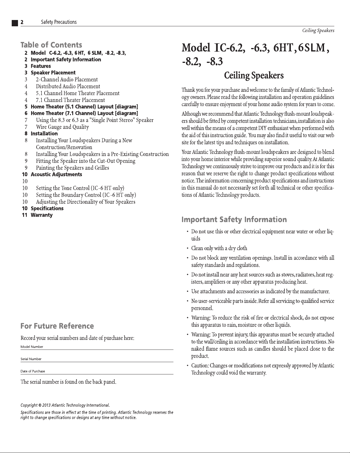
2-Channel Audio Placement
In standard two channel audio systems, the ideal distance between the left
and right channel speakers should be in the range of 6-10 feet (1.8-3.0m)
apart. If the layout of the joists and light fittings permit, the speakers should
be equidistant from the most commonly used listening position.
Stereo Sound Layout
To ensure the best stereo effect, place
speakers along a common wall, roughly equal
distances from the intended listening area.
Left
Speaker
Listening Area
Atlantic Technology ceiling loudspeakers feature swivelling tweeters to aim sound
directly at the listening area to compensate for offset mounting.
Right
Speaker
Page 4
4
Distributed Audio Speaker Placement
IC Series Thin Bezel Ceiling Speakers
Distributed Audio Placement
Atlantic Technology loudspeakers possess extremely smooth and predictable off-axis frequency response. However, in some cases, where the room
is large, you may wish to consider the use of two (or more) pairs of speakers in order to provide a wider and more even dispersion of sound. A more
even distribution of sound in this way means that people within the room
are more likely to be equidistant from the speakers so that there are less
“hot” or “cold” spots of audio volume.
When connecting more than one pair of speakers to an amplifier it is vital
to maintain a compatible impedance load between the amplifier and speakers. Your amplifier will specify an acceptable impedance range which it can
handle and you must ensure you do not drop the total impedance below
that specified minimum level or you may damage your amplifier. If in doubt
you should consult a professional installer or contact Atlantic Technology
directly before commencing installation.
As an example, a typical amplifier may specify an acceptable operational
impedance range of 4 to 8 ohms. If you connect two pairs of Atlantic Technology 8-ohm loudspeakers in parallel, the impedance you will present to
the amplifier is 4 ohms. This is within acceptable limits of most quality
amplifiers. If you connect them in series, you will present 16 ohms resistance to the amplifier which will reduce the available power, but be a very
“safe” load for the amplifier.
Generally, you should not connect two 4-ohm loudspeakers in parallel,
because then the impedance will be 2 ohms and may damage your amplifier. If they are connected in series, the impedance will be 8 ohms and therefore within acceptable limits.
Please note that, much like attaching a trailer to the back of a car, attaching a second set of speakers to an amplifier puts an additional load on the
amplifier (or engine). This makes it work harder for the same performance
or it may simply not have the power to perform satisfactorily. You need to
check the capability of your chosen amplifier before attempting multiple
speaker connection.
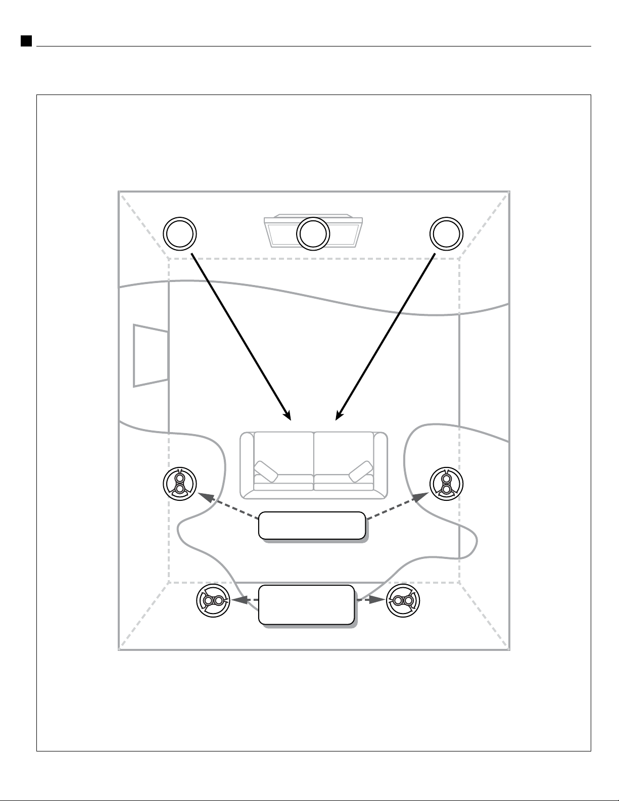
5.1 Channel Home Theater Placement
Front of room
towards the front of the theater (see diagram on page 5).
When using the 6.3 or 8.3 speakers as
side channel speakers in a 5.1 channel
home theater environment, they should
be located directly alongside the listening area to just slightly (1-2 ft.) behind
it. If you are setting them to Dipole
(see diagram below), the tweeter with
the single leg of the bridge should face
7.1 Channel Home Theater Placement
When using the 6.3 or 8.3 speakers as side and back channel speakers in
a 7.1 channel home theater environment, they should be located directly
alongside the listening area to just slightly (1-2 ft.) behind it. If you are setting them to Dipole, the tweeter with the single leg of the bridge should
face towards the front of the theater (see diagram on page 6). The back
speakers should be behind the listening position, about 1-2 ft. away from
the rear wall if possible.
rear of speaker
BIPOLE
Generally, the best results are when the .3 back
speakers are set to Dipole, whether or not the .3 side
speakers are set to Dipole.
You may use the 6.2 or 8.2 as either side or back
surround speakers, with excellent results, in either
a 5.1 or 7.1 home theater system. If you are mix-
DIPOLE
ing .3 and .2 surround speakers in a 7.1 system, it
is advisable to use the .3’s as side surrounds, set to
Dipole. Use the angle tweeter capability on the .2 speakers to aim the tweeter
away from the listeners, towards the wall, to create a more non-localizable,
diffuse surround effect.
LCR Use in a Home Theater
The IC-6 HT is ideally suited for front LCR use in a home theater system
when wall-mounted or free-standing speakers are not desired.
Mount the speakers so that the woofers are angled towards the listening
position. (See diagrams on page 5 and 6)
Page 5

5
Instruction Manual
Home Theater Layout
Home Theater (5.1 Channel) Layout
Left
Front
Left
Surround
Center Right
Listening/
Viewing Area
Surround
Front
Right
Page 6
6
Home Theater Layout
Home Theater (7.1 channel) Layout
IC Series Thin Bezel Ceiling Speakers
Left
Front
Left
Surround
Center Right
Listening/
Viewing Area
Set to “Dipole”
Surround
Front
Right
Left
Back
If Using .3’s
set to “Dipole”
Right
Back
Page 7
7
Instruction Manual
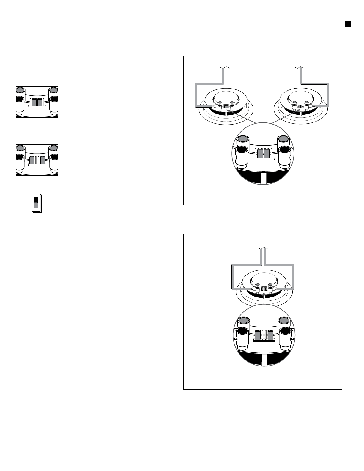
Single-Point Stereo
Using the 8.3 or 6.3 as a “Single Point Stereo”
Speaker
Your IC-6.3/8.3 comes from the factory ready for conventional (mono) use.
This means a single speaker will handle a single channel of information,
such as what is required for surround channel use.
If you are going to use your .3 speaker for surround
channel duties, leave the jumpers in the configuration
shown to the left.
The 6.3 and 8.3 speakers feature two sets of push-
to-connect terminals. You may connect the speaker
wires to either set of terminals but it is essential that the correct polarity of
the connections to your amplifier is maintained.
If you want to use the IC-6.3/8.3 as a “single-point
stereo” speaker (where the left and right channels are
handled by the single unit), then move the jumpers to
the position shown left. Set the Bipole/Dipole switch
to the Bipole position so the tweeter is in phase with
rear of speaker
BIPOLE
DIPOLE
which speaker terminals are connected to the left or right channel on your
amplifier, but correct polarity is critical.
the woofer.
Connect the speaker wires for one channel to one
set of terminals, and the speaker wires for the other
channel to the other set of terminals.
If the sound from the speaker lacks definition, it is
likely the polarity is incorrect. It does not matter
Using two IC-6.3 or IC-8.3 speakers for stereo
(conventional/surround use)
Set jumpers to mono
position as shown
Using one IC-6.3 or IC-8.3 for single point stereo setup
Wire Gauge and Quality
A good rule of thumb when installing speakers is to use 16-gauge wire for
runs up to about 50 feet. Use 14-gauge wire for longer runs. 18-gauge is
acceptable for short runs less than about 25 feet. Use speaker wire whose
insulation meets local building codes. Consult a knowledgeable installer
for more details.
Set jumpers to stereo
position as shown
Page 8

8
Installation
Installation
IC Series Thin Bezel Ceiling Speakers
Installing Your Loudspeakers During a New
Construction/Renovation
If you are installing your flush-mount Atlantic Technology loudspeakers
during a renovation or new construction, you will probably have the benefit of exposed joists, ceilings and stud walls. This makes the running of the
speaker wire much more straightforward.
The mounting surfaces used should be at least 1/2" (10mm) thick to ensure
safety and speaker stability.
Your Atlantic Technology loudspeakers have optional pre-construction
brackets. These can be used to assist with installation. They can be nailed
or stapled between the joists or studs in the planned speaker position with
the flange of the speaker cutout facing out.
As the plasterboard is fitted you will find it easier to accurately cut out the
necessary hole for your Atlantic Technology loudspeaker reducing installation time and debris when the speakers are being fitted.
installing pre-construction bracket
Exposed ceiling joists
Installing Your Loudspeakers in a Pre-Existing
Construction
If you are installing your flush-mount Atlantic Technology loudspeakers
in existing construction, installation may be a little more challenging as
you may have to fish cables to minimize any disruption to the decor of
your home.
The first step in installing flush-mount loudspeakers in existing construction is to establish the location of the ceiling joists. You may be able to do
this by lifting upstairs floorboards or using stud finding tools. If not, you
may need to make pilot holes and a probe but recognize this may entail
making cosmetic repairs afterwards.
Once a suitable location is identified, you will need to cut out the correct
size opening in the surface of the plasterboard using the supplied cut-out
template. You should make a pilot hole first and take care not to cut into
pre-existing electrical cables or plumbing.
You will need to run speaker cable from the opening back to the amplifier (in the case of the Single-stereo model IC-8.3 or 6.3, you will need
two cables). Ensure you comply with any building codes that may apply
in your location.
Using the template to cut a hole
Mounting with pre-construction bracket
Ceiling board
Atlantic 6.5-inch
Mounting Template
Center
Remove scrim before
painting grille.
8”
(202mm)
NOTE:
When installing in an existing construction, take care not to
cut through any existing wiring or plumbing.
Page 9

9
0
+
3
-
3
-
3
0
+
3
T
W
E
E
T
E
R
0
+
3
-
3
+
3
Fitting the Speaker
Instruction Manual
Fitting the Speaker into the Cut-Out Opening
Before inserting the speaker into the opening in the wall/ceiling, attach the
speaker cable(s) to the speaker, taking care to ensure the correct polarity of
the speaker wires as this is critical to the correct operation of the speakers.
Insert the speaker housing into the opening and tighten the mounting
screws to engage the “dog-leg” fasteners. Be careful to not over-tighten.
The “dog-leg” fasteners will clamp the speaker frame and the mounting
surface together.
To attach the speaker grille, position the grille over the speaker frame.
Powerful magnets embedded in the frame will draw the grille towards
the frame. Be sure the grille is centered properly over the frame and that it
“snugs” down to the correct centered position.
Fitting speaker into cutout
Acoustic Adjustments
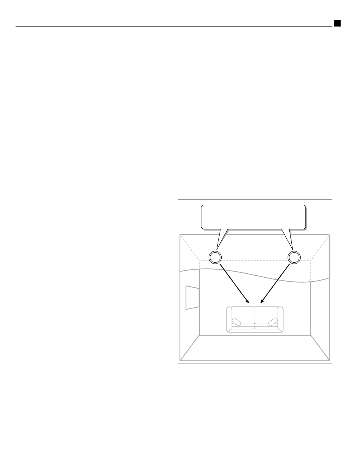
Dipole/Bipole Operation of IC-8.3 and IC-6.3
Speaker
In Dipole mode the .3’s produce ambience with minimal localization (best
for most movies and video soundtracks). In Bipole mode they produce
more localizable sound (preferred for some music recordings).
rear of speaker
BIPOLE
DIPOLE
in the listening area, we recommend that you begin with the dipole mode,
as this usually delivers the most involving and believable surround performance in most situations.
Setting the Tone Control (IC-6 HT only)
The Atlantic Technology IC-6 HT loudspeaker features a baffle-mounted
the treble.
Switching between Dipole and Bipole mode is easily accomplished using a slide switch located on
the rear of the speaker. Please note that the vast
majority of the time in movies and TV broadcasts
the surround speakers are called upon to reproduce
the environmental sounds that are used as cues to
help get you immersed in the scene on the screen.
Once the surround speakers are properly positioned
level control for treble frequencies. The level
control will help you to fine-tune the performance of the speaker to meet room acoustics issues or listener preferences.
The level control can be adjusted to provide 3dB of boost or 3dB of reduction of
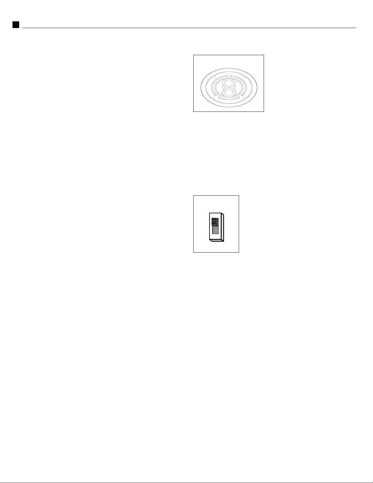
Painting the Speakers and Grilles
Both the speaker frames and the grilles can be painted, if desired. We recommend doing this before installation. Always paint the grilles separately
from the speaker itself. First, remove the white scrim cloth from behind the
grille. The grilles should only be spray painted very lightly to avoid clogging
the fine mesh of the grille and restricting the sound. Once the grille is dry,
replace the scrim cloth by gently placing it behind the grille. No adhesive is
necessary—gravity will keep it in place.
Only install the speakers and grilles once the paint has dried thoroughly.
Painting the grilles
1. Remove Scrim 2. Paint Grille 3. Reapply Scrim
Setting the Boundary Control (IC-6 HT only)
The Atlantic Technology IC-6 HT loudspeaker has a baffle-mounted Bound-
ary control that adjusts the speaker’s midbass response to compensate for when it is
placed very close (within a foot or so) to a
nearby wall (a “Boundary”). Such placement
can exaggerate the mid-bass response of
the speaker, resulting in a bloated or boomy
sound. Engaging the Boundary control “-3” compensates for such positioning and returns the speaker’s response to normal. Use the "+3" setting
when the speaker is mounted well away (and more than 5 feet) from all
nearby walls.
Adjusting the Directionality of Your Speakers
NOTE:
Do not apply pressure to the tweeter dome itself. The pivoting
tweeter can be used to direct sound towards or away from a listening area. To pivot the tweeter, apply light pressure to the plastic ring
around the outside edge of the tweeter.
If your speakers are widely separated and the music fails to blend into a
central image when the system is operated in stereo mode, you should orientate the tweeters toward the listening area.
Page 10

SLM
Page 11

11
Instruction Manual
Warranty
Warranty
First, we’d like to thank you for purchasing an Atlantic Technology product.
We wish you many years of enjoyment and satisfaction from it.
Second, be aware that you don’t have to send in any Warranty card to be
covered by the Limited Warranty. All you need to do is keep your original
Invoice or Bill of Sale for proof of purchase, meet the stated requirements,
and follow the instructions listed within that Warranty. Please attach your
Original Invoice or Bill of Sale to this manual as proof of purchase and keep
them in a safe place.
VERY IMPORTANT NOTE:
OGY PRODUCTS CARRY ONLY A 90 DAY LIMITED WARRANTY. YOU
MUST MEET ALL THE BELOW REQUIREMENTS AND REGISTER ONLINE
IN ORDER TO BE COVERED BY THE FREE EXTENDED SERVICE AGREE
MENT TO ASSURE EXTENDED FREE PROTECTION!!
PLEASE NOTE THAT ATLANTIC TECHNOL-
-
Free Extended Service Agreement
Atlantic Technology offers a free Extended Service Agreement that provides
enhanced protection against product defects. In order to qualify for the free
Extended Service Agreement you must:
1. Have purchased your Atlantic Technology products from an Authorized
Atlantic Technology Reseller or Installer.
2. Go to www.atlantictechnology.com and click on Support>Register Your
Warranty. Fill out the required information. Be sure to have your home
address, name, address and invoice from the business you purchased,
and the serial numbers of all Atlantic Technology products purchased.
THIS MUST BE DONE WITHIN 30 DAYS OF PURCHASE.
3. If you purchased multiple Atlantic Technology products you will be able
to enter them all using one online form. Model and Serial numbers can
be found on the back of each unit and on the outside of their respective
boxes.
Once all the criteria have been met, you will receive, by return email, a free
Extended Service Agreement that entitles you to additional coverage against
defects in workmanship and manufacturing for a period of up to 5 years on
passive speakers and up to 1 year on powered speakers (including subwoofers). This coverage is in addition to the 90 Day Limited Warranty included
with all Atlantic Technology products.
If you are not able to register your product using the internet, please call
customer service at 781-762-6300.
Limited Warranty
Statement of Warranty: Atlantic Technology International Corp. warrants
Atlantic Technology Products to be free from defects in material and workmanship for 90 days from the time of original purchase. This Warranty covers the
original retail purchaser of this product only and is valid only in the Continental
United States, Alaska, and Hawaii and all US Possessions.
Extended Service Agreement (only available in the Continental United
States, Alaska, and Hawaii and all US Possessions): You must complete the
Extended Service Agreement application, and meet all of the purchase criteria
stated on that application, to receive an Extended Service Agreement that covers
your Atlantic Technology products well beyond the standard 90 day Warranty.
To obtain Warranty service: Please contact your local Atlantic Technology
reseller to determine if they are an Authorized Repair Center for Atlantic
Technology products. You will need your original Invoice or Bill of Sale to
prove Warranty eligibility. If your local dealer is not an Authorized Warranty
Center you may contact us at 781-762-6300 for further help or to send the
product back to us for service and repair. You must first get a Return Authorization Number from us to ship the product back, so it is imperative that
you call us first.
What we are responsible for: We will pay for all labor and parts for covered
items. If the repairs are eligible for coverage under the terms of this Warranty
we will also pay for return shipping charges to you.
What you are responsible for: You must pack the product properly for safe
shipping to your Authorized Dealer or us. You are responsible to pay for all
packing, shipping, and insurance costs to get the unit(s) back to Atlantic
Technology or your Authorized Dealer.
Optional replacement: We, at our option, may replace rather than repair
your Atlantic Technology product with a new or reconditioned one of the
same or similar design. The repair or replacement will be warranted for 90
days from date of receipt back to you. All details in terms of eligibility for
an Extended Service Agreement will carry over from the original purchase
to the replacement item.
What this Warranty does not cover: This Warranty does not cover defects
resulting from accidents, damage while in transit, alterations, unauthorized
repair, failure to follow instructions, misuse, fire, flood, and Acts of God.
This Warranty will be void if the product’s serial number has been altered
or removed or if the product has been modified or defaced.
Exclusions and Limitations: Implied warranties, including those of fitness
for a particular purpose and merchantability (an unwritten warranty that
the product is fit for ordinary use) are limited to the period of any Warranty
granted hereby. We will not pay for loss of time, inconvenience, loss of use, or
property damage caused by your Atlantic Technology product or its failure
to work, or any other incidental or consequential damages.
State law rights: Some states do not allow the exclusion or limitation of
incidental or consequential damages, so the above limitation or exclusion
may not apply to you. This Warranty gives you specific legal rights, and you
may have other rights which vary from state to state.
This Warranty is valid only when Atlantic Technology products are purchased from an Authorized Atlantic Technology Reseller in the Continental
United States, Alaska, and Hawaii and all US Possessions. If you purchase
Atlantic Technology products outside the United States please consult your
local distributor or reseller for applicable Warranty coverage and restrictions.
Should you have any questions or problems please feel free to contact us at
781-762-6300 or through our web site, www.atlantictechnology.com.
Page 12

343 Vanderbilt Avenue Norwood, MA 02062 (781) 762-6300 www.atlantictechnology.com
015-1017-B
 Loading...