


TR 80
Atlantic Boilers TR 80, TR 300, TR 105, TR 150, TR 200 Installation, Operating And Maintenance Manual
...
ATLANTIC BOILERS, PO BOX 11, ASHTON UNDER LYNE, OL6 7TR T: 0161 621 5960 E: info@atlanticboilers.com www.atlanticboilers.com
FOR TECHNICAL HELP/ADVICE Call 0161 621 5960
or email info@atlanticboilers.com
FOR FULL PRODUCT RANGE & LITERATURE
Visit www.atlanticboilers.com
TR 3 PASS HOT WATER BOILERS
INSTALLATION, OPERATING AND MAINTENANCE
INSTRUCTION MANUAL

°
“The Heating Engineer”
06042007
5
CONTENTS
o Properties of liquid/gas fuelled boilers…………………………………….. 6
o Manufacturing and testing standards applied………………………….. 6
o Introduction……………………………………………………………………………….. 7
o Boiler dimensions……………………………………………………………………….. 9
o Boiler operating personnel………………………………………………………... 10
o Transportation and temporary storage……………………………………... 10
o Boiler installation…………………………………………………………………………. 11
o Expansion tank and safety pipes…………………………………………………. 12
o Burner selection and installation…………………………………………………. 17
o Combustion chamber dimensions……………………………………………….. 18
o Fuel selection and storage ………………………………………………………….. 19
o Filling the system with water……………………………………………………….. 19
o Preparation of the boiler for operation………………………………………… 20
o Safety rules
……………………………………………………………………………………………………………………………………….
21
o Putting boiler in operating……………………………………………………………. 23
o Heating system adjustments
……………………………………………………………………………………………
25
o Discharging the boiler water……………………………………………………….. 26
o Taking boiler out operation…………………………………………………………. 26
o Prevention of low temperature corrosion…………………………………… 27
o Inspection and maintenance of boiler……………………………………….. 28
o General maintenance………………………………………………………………….. 28
o Hydrostatic test……………………………………………………………………………. 29
o General boiler malfunctions………………………………………………………… 30
o Boiler control panel installation
.................................................... ................
32
o Control panel dimensions
.................................................... .................................
34
o Boiler control panel electrical schema…………………………
………………………..
35
o Installation circuit diagram………………………………………………………….. 37
o Boiler feed water and boiler water chemical characteristics ……… 38
o Boiler life span………………………………………………………………………………. 39
o Authorized services………………………………………………………………………. 40
erensan
erensan°
“The Heating Engineer”
06042007
7
INTRODUCTION
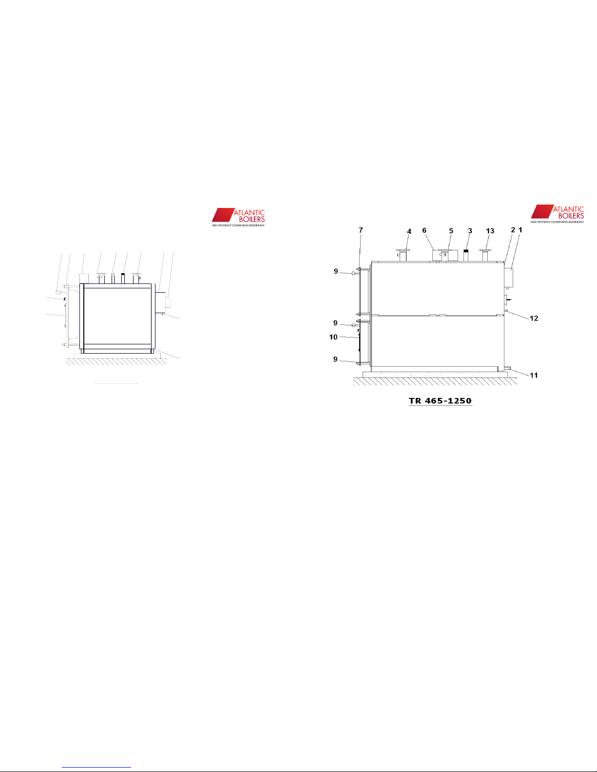
TR 80-350
10
9
8
7
6
5
4
3
12
12
11
13
1. Chimney duct
2. Smoke chest
3. Expansion tank connection sleeve
4. Boiler return
5. Boiler outlet
6. Control panel (CP)
7. Door nuts
8. Handle
9. Flame observation port
10. Burner adapter flange
11. Boiler filling&discharge
12. Condensation water sleeve
13. Sanitary hot water connection sleeve
erensan°
“The Heating Engineer”
06042007
8
1. Chimney duct
2. Smoke chest
3. Expansion tank connection sleeve
4. Boiler return
5. Boiler outlet
6. Control panel (CP)
7. Door nuts
8. Handle
9. Flame observation port
10. Burner adapter flange
11. Boiler filling discharge
12. Condensation water sleeve
13. Sanitary hot water connection sleeve
erensan°
“The Heating Engineer”
06042007
9
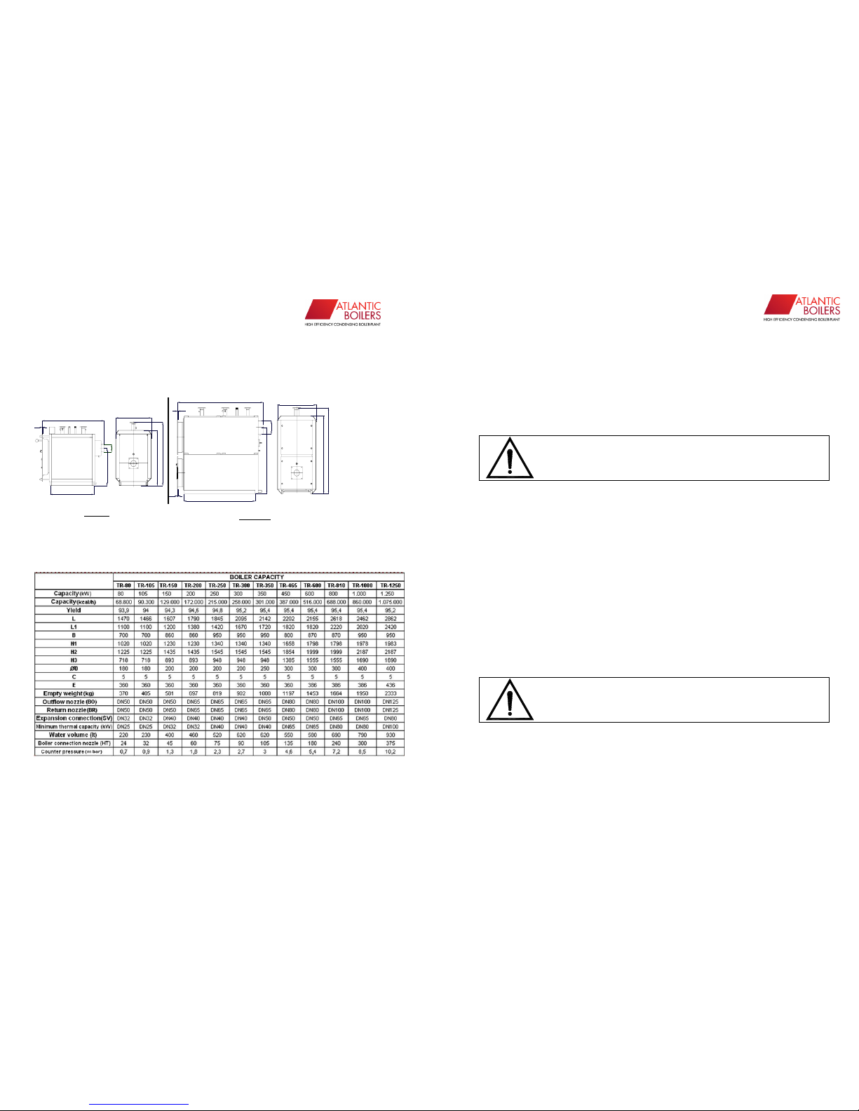
BOILER DIMENSIONS
TR 80-350
TR 450-1250
ØD
KD KG EV S.K
H3
L1
L
C
B
H2
H1
H3
ØD
B
H1
H2
L1
C
C
L
erensan°
“The Heating Engineer”
06042007
10
BOILER OPERATING PERSONNEL
Boiler operating personnel (boiler operator) should be knowledgeable
about general boiler failures and their reparation, as well as the tasks
and working principles of all measurement, adjustment, control and
safety devices on the system.
The boiler operator should have an official document (boiler operator
certificate) verifying his expertise on the abovementioned issues.
TRANSPORTATION AND TEMPORARY STORAGE:
• The boiler should be transported using the lifting and transportation
points by detaching the top cladding sheet and appropriate equipment.
• For horizontal movement; where it is not possible to utilize a winch,
horizontal displacement is possible through controlled sliding on pipes.
• The boiler should be protected against mechanical blows and collisions
during loading, transportation and unloading.
• It must be protected against damages resulting from moisture and
external mechanical factors that may arise during temporary storage
before transportation and installation.
MAKE SURE THAT THE BOILER
PERSONNEL POSSESS BOILER OPERATOR
USE THE BOILER COMPLYING WITH
WARNINGS AND RECOMMENDATIONS IN
THIS
PROCEDURE !

erensan°
“The Heating Engineer”
06042007
11
BOILER INSTALLATION
• Install the boiler in the boiler room at the installation site on a
foundation elevated from the floor.
• Make the boiler mechanical connections as per the installation circuit
diagram.
• Boiler installation site should comply with the related standards and
procedures. It must have a door opening towards the outside, a fresh air
inlet duct at floor level and a polluted air discharge chimney duct at ceiling
level (apart from the boiler chimney). The door and the window frames
must be of non-flammable material.
• The burner, the boiler control panel (if any) and the pre-heater
connections should be performed by eligible technical personnel in
compliance with the burner user manual and vendor installation diagram.
• The boiler must be used with the boiler control panel. (We also
recommend a thermometer to be placed on the ½” sleeve located on the
boiler return pipe.)
A hydrometer (open expansion) or manometer (closed expansion) should
be placed on the boiler outlet pipe or collector.
• The boiler may be used in an open or closed expansion system. In case
it is used in a closed expansion system; a closed expansion tank suitable
for the total boiler and central heating water volume should be used at
building static water level pressure and with adjusted gas side pressure.
The closed expansion tank should be connected to the expansion nozzle
directly on the boiler or to the boiler main outlet or return pipe provided
that there is no stop gate valve. A pressure relief valve with opening
pressure of 1,05 bars over the boiler operating pressure should be used.
• More than one boiler should not be connected to the same chimney.
• The boiler must be provided with a chimney and smoke channel in
compliance with the regulations and standards of the authorized
institutions regarding the fuel and smoke gas debit used.
• Our boiler has been designed for 90-70 C, stabilizing collector and
secondary circulation pump must be used in the system for different
temperature applications.
• The number 12 condensation water sleeve located in the figures of
pages 7 and 8 must be plugged with the boiler room output by attaching a
hose nippel and a hose to it.
erensan°
“The Heating Engineer”
06042007
12
In order to prevent battery corrosion, the boiler must be
grounded with,
a) 0.5m
2
, 2mm thick copper sheet,
b) 0.5m
2
, 3mm thick hot dip galvanized sheet
c) Massive copper bar electrodes.
EXPANSION TANK AND SAFETY PIPES
It is essential for the water not to be in direct contact with the air and the
temperature not to rise above 100°C in open expansion hot water heating
system. There should be outflow and return safety pipes between the
boiler and the expansion container fully and independently, without any
valves interrupting it in order to ensure the contact of water with the air
and to ensure that this connection is not cut off by mistake or due to
negligence. The safety valves should be installed without narrowing and
continually rising towards the expansion tank.
Access to the outflow safety pipe and the expansion tank can be either
from top or bottom. However the return safety pipe must be connected
from the bottom. The diameters for both pipes based on tank capacity can
be obtained from the table below. The safety pipes should never be
smaller than 1”.
erensan°
“The Heating Engineer”
06042007
13
Their diameters can be calculated by the following formula.
df = 15+1,5*(Qk /1000)½ [mm]
d
g = 15+(Qk /1000)
½
[mm]
Monitor = ½"
It is strongly recommended to place a circulation connection and tap
between the outflow safety pipe and expansion tank.
No hardware such as valve or check valve that clog the circulation should
be placed on the safety valves.
The volume of the expansion tank is calculated based on the expansion as
a result of the temperature rise of the water in the entire system from
10°C to tm °C. The expansion tank volume in systems with normal hot
water of 90/70 °C
can be taken as Vi = 0,06*V
S
(liter)
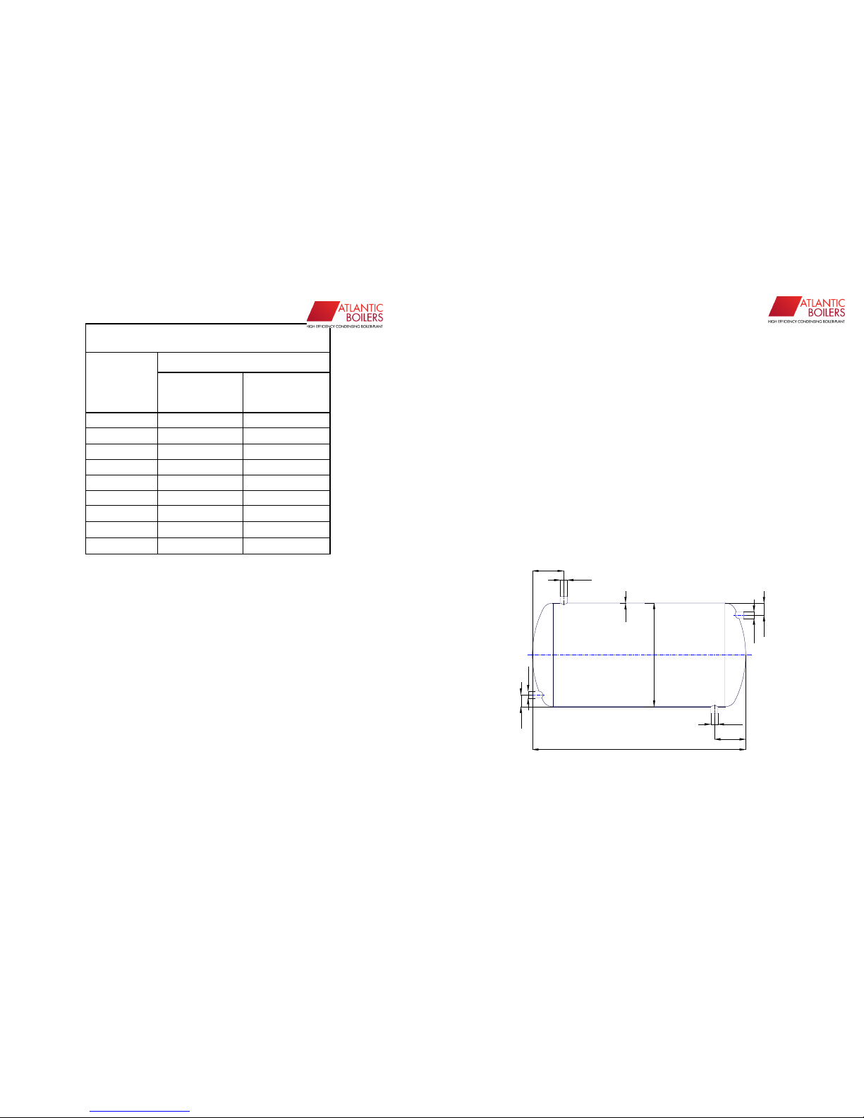
Safety Pipe Diameters
Boiler capacity (kcal/h)
DIAMETER
Outflow pipe
Return pipe
25 - 1" 50.000 100.000
32 - 1 1/4" 130.000 209.000
40 - 1 1/2" 280.000 630.000
50 - 2" 550.000 1.230.000
60 - 2 1/2" 900.000 2.000.000
70 1400.000 3.000.000
80 1900.000 4.200.000
90 2500.000 5.600.000
100 3200.000 7.200.000
°
“The Heating Engineer”
06042007
14
(Vs, is the total water amount in the system in liters)
V
S
= W * Qk (liter)
Qk = Boiler heating power (kW)
W= Specific water amount;
When convector is used : 5.20 lt/kW
When panel radiator is used : 8.33 lt/kW
When cast radiator is used : 12.00 lt/kW
With heating from flooring : 18.50 lt/kw
are the values.
The empirical volume of the expansion tank can be calculated roughly as
follows.
Vi = 0.002 * Qk (liter)
Note: The volumes obtained are the useful volume of the tank, and the
volume of the tank will be taken as 25% above than this volume.
The expansion tanks should conform to TS 713.
(DIN 4806 should be referred to for the matters that are not addressed by
TS 713.)
d1
d2
l3
l2
d2
l1
l2
d2
l3
d2
s
 Loading...