

Atlantic PLM 12KE-410, PLM9KE-410, PLM15KE-410, PLM9KEH-410, PLM12KEH-410 Instruction Manual
...Page 1
s
col
b
o
nom
M
LP
PLM
ENGLISH
INSTRUCTION MANUAL
9KE-410 /12KE-410 /15KE-410
PLUS HEATER VERSIONS
Page 2

Page 3
3
IMPORTANT
• The unit is designed for indoor operation.
• Rating: This unit must be connected to a 220-240 V / 50 Hz earthed outlet.
• The installation must be in accordance with regulations of the country where the unit is
use
d.
If you are in any doubt about the electrical installation, have it checked and if necessary
modified by a qualified electrician.
• The air conditioner is safe. However, as with other electrical appliances, use it with care.
• Keep out of the reach of children.
• Do not clean the air conditioner by spraying it or immersing it in water.
• Do not insert any object into the opening of the air conditioner.
• Disconnect it from the mains before cleaning the unit or any of its components.
• Never connect the unit to an electrical outlet using an extension cord. If an outlet is not
available, one should be installed by a licensed electrician.
• Any service other than regular cleaning or filter replacement should be performed by an
authorized service representative. Failure to do so could result in a loss of warranty.
• A damaged supply cord should be replaced by the manufacturer, its service agent or a
qualified
person in order to avoid a hazard.
WARNING
• Never operate this appliance if it has a damaged cord or plug. Do not lead the cord over
sharp
edges.
• Don’t lift or move by pushing the air conditioner at the rear, but always at the front side.
• Keep a minimal 0.5 m safety distance between the appliance with the electrical heater
and any inflammable surface.
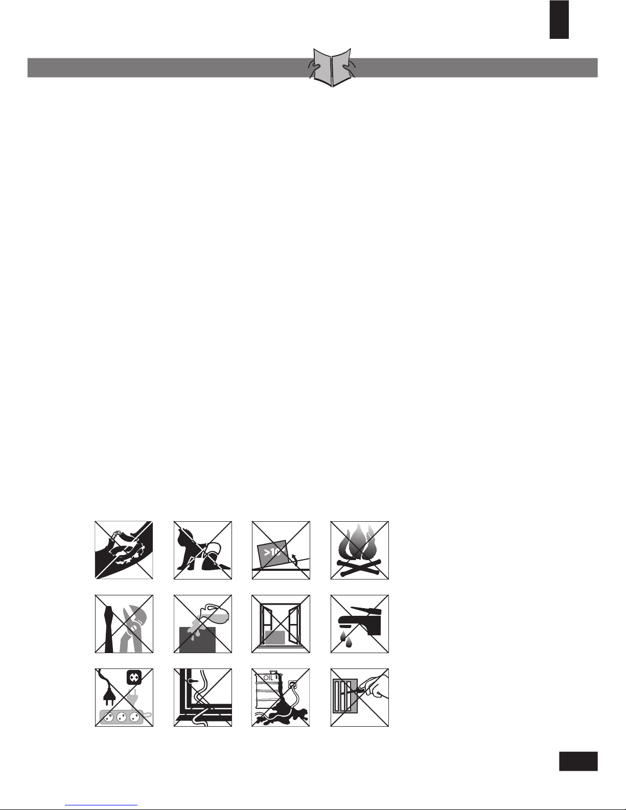
a. Do not use a damaged cable.
b. Keep out of reach of children.
c. Do not place unevenly.
d. Do not place near a heat source.
e. Do not repair.
f. Do not spill.
h. Do not immerse in water.
i. Do not use an extension cord.
j. Do not clamp or bend the cable.
k. Do not bring in contact with
chemicals.
l. Do not insert anything.
g. Do not place in front of an open
window.
SAFETY INSTRUCTIONS
a
b c d
e
f g h
i j k l
Page 4
44
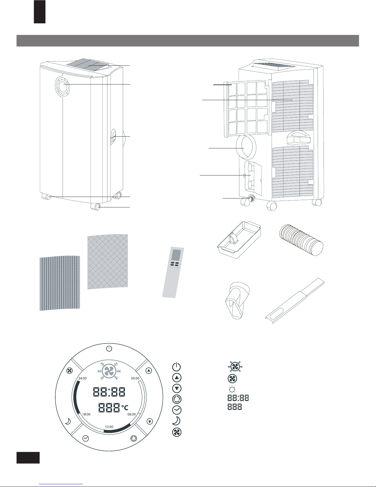
PARTS
Air inlet
Filter holder
Exhaust
air
outlet
Cable
storage
Water stopper /
drainage
point
Slide
bar
connector
Air
outlet
Control
panel
Carrying
handle
Caster
wheels
Air filter
Telescopic slide bar
Exhaust hoseWater container
Remo
te control
Controls
ON/OFF
UP
DOWN
MODE
TIMER
SLEEP
FAN SPEED
Displ
ay
COOLING
FAN
HOURS:MINUTES
TEMPERATURE
HEAT (for models with heater only)
Page 5

5
INSTALLATION
OPERATION
ON/OFF
Press
to switch the unit on or off. A buzzer will beep, and the LCD will display 12:00
o’clock as default.
Setting the clock
Press the
button for 3 seconds to set the clock. The 2 left digits of the 4 digits on the
LCD-display will flash. Press
or to adjust the hour. Press momentarily, the 2 right
digits of the 4 digits will flash. Press
or to adjust the minutes of the clock. Press the
button for 3 seconds again to activate the clock.
CM
CM
WARNING! Before using the air conditioner it should be left in an upright position for at least 2 hours.
This unit can easily be moved from one room to another. In doing so keep this in mind:
–
Ensure that the unit is positioned upright, on a level surface and 50 cm away from obstacles.
– To place the loose filters in the filter holder.
• Take the filter holder out of the air conditioner
• Release the filter fixer and place the active carbon filter (black) and 3M™ High Air Flow
filter (white), where included, in the filter holder.
• Place the filter fixer back in the holder.
• Place the filter holder back in the air conditioner.
–
Do not operate the unit inside the bathroom, shower, or in any other very humid environment.
– Connect the hose to the unit by turning it clockwise (at least 5 turns).
– Similarly, connect the hose to the slide bar connector as far as possible.
– Place the telescopic slide bar in the open window or door and
adjust
the length to fill as much open space as possible.
– Put the slide bar connector in the opening in the telescopic slide
ba
r.
– Close the window or door as much as possible to prevent outside
air
entering the room.
– Ensure that the slide bar connector has a free flow outside.
Impo
rtant
The flexible exhaust hose can be extended from 500 to 1500 mm for mounting. This length
has
been designed especially according to the specifications of the air conditioner. Do not
use
an extension or exchange for a different hose as that may lead to malfunctioning. The
exhaust air must flow freely, any blockage can lead to overheating of the air conditioner.
Take care to prevent any sharp bow or bend in the exhaust.
Page 6

66
Setting the temperature
If you want to change the set temperature press
or to set the temperature. The 2 digit
displ
ay will indicate the set temperature.
Note: Reaching the set temperature depends on the room and outdoor climatic conditions.
Mode
switch
Press the
button successively until the icon representing the desired mode is appearing
(=>
Cool => Fan => Heat(for models with heater only) => etc). On the LCD-display you will see:
Cooling Fan only Heat
Each time the unit starts, it starts operating in cool mode with a set temperature of 22°C. The
fan
speed will be selected automatically. Heat mode is only available on EH models.
Fan speed
If you prefer a constant fan speed instead of the auto fan speed, press the button
successively; the fan icon on the LCD-display will rotate accordingly.
• Fast - for the turbo speed
• Normal - for the medium speed
• Slow - for the slow speed
• Alternating - for the auto fan speed (in the cooling mode only!)
Switching LCD backlight ON/OFF
• If you prefer to switch the LCD backlight off, push the and buttons at the same
time. After blinking twice the backlihgt will be switched off after 3 sec.
• By pushing any button on the control panel the backlight will switch on again.
Heat (for models with heater only)
EH
models feature a 1680 W electric heater that can heat a room on cooler days. With
the
mode switch select , set the desired temperature and the unit will heat until this
temperature is reached. Fan speed is selected automatically. Do not place the unit near
anything that could catch fire or be scorched. Do not obstruct the air outlet. The heat
function will operate with or without the hose attached.
Timer
For all of the following TIMER programming, proceed firstly with these standard steps:
• Press the button briefly; the 2 left digits of the 4 digits on the LCD display are flashing.
• Press or to adjust the hour.
• Press the button briefly again, the 2 right digits of the 4 digits are flashing.
• Press or to adjust the minutes of the clock in intervals of 5 minutes. The timer is set.
After 10 seconds the time display returns.
Programming the timer for ON - when the unit is OFF.
• Perform the standard steps as described above.
The circular time scale will be on between the ON programmed times
until
24:00. The flashing bar on the time scale indicates the real time and
moves a segment ahead every 30 minutes until it reaches the ON timer
tim
e, then the black segments in the circular time scale will disappear.
Timer example
Page 7

7
Repeat OFF and ON
Programming the timer for repeat OFF and ON - when the unit is RUNNING.
• Perform the standard steps as described above.
• Repeat the above procedure while the digits are still flashing for setting the ON.
The circular time scale will be ON between 00:00 to the time set with the timer to OFF and
from that time until 24:00. The flashing bar on the time scale indicates the real time and
moves a segment ahead every 30 minutes. The unit will operate daily according to the timer
settin
g.
Repe
at ON and OFF
Programming the timer for repeat ON and OFF - when the unit is NOT RUNNING.
• Perform the standard steps as described above.
• Repeat the above procedure while the digits are still flashing for setting the OFF.
The circular time scale will be OFF between 00:00 to the time set with the timer to ON and
from that time until 24:00. The flashing bar on the time scale indicates the real time and
moves a segment ahead every 30 minutes. The unit will operate daily according to the timer
settin
g.
After a power failure, or after the unit has been unplugged, you will have to program the
timer settings again.
Cancelling the timer function
In order to cancel the timer programming press the
button momentarily, then it will
return to the time display. The daily mode will be cancelled as well. The black segments in
the
circular time scale will disappear.
Air flow
Di
rect the air flow by adjusting the grill on top of the air conditioner.
Move the grill, by pushing or pulling, in the middle (see illustration). This
will
avoid uneven positioning of the grill. Adjusting the air flow is also
possible by moving the direction of the vertical louvers.
Sleep
mode
The sleep mode function adjusts the set temperature of the unit to the thermal needs of the
body
falling asleep as follow:
• In the COOL or AUTO COOL mode
• Default fan speed: LOW
• Press the button to operate the sleep mode. Press the button again in order to
cancel the sleep mode.
The set temperature will increase 1°C after 1 hour and a further 1°C after 2 hours.
• No FAN mode under SLEEP mode operation
Programming the timer for OFF - when the unit is RUNNING.
• Perform the standard steps as described above.
The circular time scale will be on between the present time to the OFF programmed time.
The flashing bar on the time scale indicates the real time and moves a segment ahead every
30
minutes until it reaches the OFF timer time, then the black segments in the circular time
scale will disappear.
Page 8

88
Dehumidification
If the unit will be used mainly as a dehumidifier just let the warm air return in the room.
Continuous drainage is then necessary and more efficient.
For continuous drainage:
• Switch off the unit and remove the plug from the mains.
• Remove the water stopper and rubber plug.
• Connect a drain tube (ø 20 mm inner dimension) onto the water outlet and extend with
extra water tube if needed.
• Place the other end in a normal drain. Make sure that the tube is free from twists and
bends. The tube must decline over its entire length.
1 2 3 4
Filter installation
• Slide out the filter holder from the unit.
• Separate the filter fixer from the filter holder (see fig. 1).
This air conditioner can be equipped with a 3-layer filter to clean the circulated room air.
a. Screen filter; to remove bigger dust particles.
b. All models: active carbon filter; to remove odours.
c.
3M™ High Air Flow filter: to remove unhealthy particles from the air such as pollen, bacteria,
animal dander and dust. Selected models have the 3M™ High Air Flow filter as standard.
However, if you require to add this to your model, or wish to purchase a replacement, call
Atlantic for details.
NOTE! The active carbon filter and the 3M™ High Air Flow filter are delivered in a plastic
packaging. Don’t forget to install these filters. These filters take away unhealthy particles out
of the room environment.
The filter holder on the rear of the unit can be opened. The active carbon filter and
3M™ High
Air Flow filter
can be installed or removed. The screen filter is part of the filter holder (see
illustration).
a. The screen filter has to be cleaned regularly with a vacuum cleaner to avoid blocking of the
air flow.
b. The positive/negative electrostatically charged
3M™ High Air Flow filter is recommended to
be changed every 3 months. Unusual dirt, construction work, pets, the presence of smoke
and running the air conditioning unit continuously can shorten the life time of the
3M™
High Air Flow filter
.
c. The active carbon filter can be cleaned with a vacuum cleaner when dusty but has to be
changed at the same time as the
3M™ High Air Flow filter.
Page 9

9
The unit responds to all signals that are sent by the remote control. There will be
a beep sound from the unit after receiving the signal.
The operation of the unit by remote control, is almost identical to the operation
by the circular control panel. The only exception is the clock function.
Instead of the button for setting the actual time and for programming the
timer, there are 3 push buttons on the remote control as follows:
• - for setting the actual time.
• TIMER ON - for programming the time when the unit is ON.
• TIMER OFF - for programming the time when the unit is OFF.
REMOTE CONTROL
EMPTYING THE INTERNAL WATER CONTAINER
Under high humidity conditions it may be necessary to empty the internal water container.
When the internal water container is full the backlight on the LCD-display flashes. The unit
will
switch off automatically.
To empty the water container do the following:
• Switch off the unit and remove the plug from the wall socket.
Do not move the unit. Doing this can result in water leakage,
damaging your floor or carpet.
• Place the water container on the floor underneath the permanent
drainage point.
• Remove the water stopper and rubber plug from the drain and let the
wa
ter run out. The water container has to be emptied several times
before all water will be drained (ca. 1.5 litres).
• Replace the rubber plug and water stopper, put the plug into the wall socket,
and
switch the unit on.
The warning signal should be off.
NOTE! When the air conditioner is in use, under normal circumstances the condensed water will
evaporate and then be discharged through the hot air outlet hose
• Remove the active carbon filter (black) and the 3M™ High Air Flow filter (white ) from its
plastic bag.
• Insert the active carbon filter into the filter holder (see fig. 2).
• Insert the 3M™ High Air Flow filter into the filter holder (see fig. 3).
• Fix the filter by reassembling the fixer into the filter holder (see fig. 4).
NOTE!
• Remove the 3M™ High Air Flow filter and active carbon filter before seasonal storage and install new
filters at the beginning of the new season. The old filters can be disposed in the ‘Non-biological
garbage container’.
• Replacement filter packages are available directly from Atlantic.
• To run the unit without active carbon filter and/or 3M™ High Air Flow filter does not do any harm to
the air conditioner. In this case odours and unhealthy dust are not removed from the circulated air.
• The screen filter must always be used.
• 3M is trademark of the 3M Company.
Page 10

1010
Never try to repair or dismantle the air conditioner yourself. Incompetent repairs result in loss of
warranty and can endanger the user and the property.
Problem Cause Solution
The air
conditioner does
not function.
No power supply. Connect to a functioning outlet and switch on.
Is the LCD light fl ashing. Empty the internal water container.
Timer function is active. Deactivate TIMER function.
The air
conditioner does
not seem to
perform.
In direct sunlight. Close curtains.
Windows or doors open, many
people or a heat source in the room.
Close doors and windows, place an extra air
conditioner.
Dirty filter. Clean or replace the filter(s).
Air inlet or air outlet blocked. Remove the blockage.
Room temperature lower than the
selected value.
Change temperature selection.
The unit is noisy. Unit stands uneven. Place on an even, solid surface (less vibrations).
The compressor
does not work.
The overheat protection is probably
activated.
Wait 3 minutes until the temperature has
decreased, then turn on the unit again.
The remote
control does not
function.
Distance too great. Make sure the remote control is correctly
aimed at the control panel.
Remote control signal not detected
by the control panel.
The batteries are drained. Replace the batteries.
To correct problems that have not been described in the table and/or if the recommended solutions fail to solve the
problem, contact an authorized service centre.
TROUBLE SHOOTING
WARNING! First of all switch off the unit and remove the plug from the wall socket.
Clean the housing with a soft, damp cloth. Never use aggressive chemicals, petrol,
detergents or other cleansing solutions.
Clean the screen filter regularly with a vacuum cleaner. See also “air filter” section.
NOTE! Never use the air conditioner without the screen filter.
CLEANING
Page 11

11
TECHNICAL DATA
STORAGE
Model
PLM9KE-410 PLM12KE-410 PLM15KE-410
PLM9KEH-41
0 PLM12KEH-410 PLM15KEH-410
Cooling capacity *
BTU/h 9000 12000 15000
kW 2.6 3.5 4.4
Power consumption -Cooling
-Heating (EH only)
0.8 1.0
1.5
kW 1.75
1.68
R410A / 5
00 R410A / 630
-Heating element (EH only)
Mains V / Hz / PH 220 - 240 / 50 / 1
Compressor model rotary
Fan speeds 3 (2+1 turbo)
Thermostatic range °C 18 - 32
Refrigerant
charge type / g R410A / 420
Dimensions
(w x h x d) mm 500 x 840 x 415
Net weight kg 33.1 34.3 39.3
* Enthalpy method at 27˚C, 60% RH.
PLM9KEHx-410 and PLM9KEx-410 series can be connected only to a supply with system impedance no more
than 0.383 Ohm.
PLM12KEHx-410 and PLM12KEx-410 series can be connected only to a supply with system impedance no
more than 0.247 Ohm.
PLM15KEHx-410 and PLM15KEx-410 series can be connected only to a supply with system impedance no
more than 0.110 Ohm
If necessary, please consult your supply authority for system impedance information.
Subje
ct to modifi cations without prior notice. For greater precision, please refer to the rating label placed on
the
product.
Empty the internal water container.
Clean the screen filter.
Remove 3M™ High Air Flow filter and active carbon filter.
• Remove the 3M™ High Air Flow filter and active carbon filter b
efore end of
season storage and install new filters at the beginning of the new seasons.
The old filters can be disposed of in the ‘Non-biological rubbis
h
container’.
• Replacement filter packages are available from Atlantic.
Put the unit in Fan Only mode for a few hours to ensure that the inside
becomes completely dry.
Store the cable as shown.
Protect the unit against dust and store in a dry place, not accessible to children.
Page 12

The purchaser is responsible for sending/returning the unit to/from an approved repairer.
Products are non-refundable 14 days from date of purchase.
0
4
9
4
2
1
3
1
9
0
1
4-
cs
lo
b
no
mo
P
LM
www.atlantics.com.au
YOUR GUARANTEE
DOMESTIC AIR CONDITIONERS
If this product is found to be defective as a result of faulty materials or workmanship
within two years from date of purchase, it will be repaired or replaced free of charge.
This guarantee is subject to the following terms:
Atlantic Australasia, must be notified of the fault
Proof of purchase must be presented to Atlantic Australasia’s nominated
representative
The warranty will be void if the product is modified, misused or repaired by an
unauthorised person
The guarantee does not cover accidental damage, misuse, or consumable items
such as filters
The guarantee after repair or replacement will not be extended beyond the original
two-year period
All replacement parts or units will be new or reconditioned
Parts or units, which are replaced, become the property of Atlantic Australasia
Atlantic Australasia disclaims any liability for incidental or consequential damages
The warranty applies for the use of the product in Australia and New Zealand.
This GUARANTEE is in addition to your Statutory Rights.
Atlantic Australasia Pty Ltd
Suite 4, 13-25 Church Street, Hawthorn, Victoria, Australia 3122
Ph. (03) 9852 9599 Fx. (03) 9852 9844 Email: ss@atlantics.com.au
Atlantic Australasia (N/Z) Pty Ltd
Ph. 0800 422 000 Email: sales@atlantics.co.nz
 Loading...