

Page 1
Code 027992
PECS P300
Document n° 1577-1 ~ 26/06/2013
Warmwasserspeicher
Ohřívače vody
Termoacumulatoare
Ballon
Bollitori
Water heater
Calentadores
Kotły
Boilers
NOTICE D’EMPLOI
MANUALE D’USO
USER MANUAL
BEDIENUNGSHANDBUCH
MANUAL DE USO
NÁVOD K OBSLUZE
MANUAL DE FOLOSIRE
INSTRUKCJA OBSŁUGI
HANDLEIDING
www.atlantic.fr
Page 2

PECS P300
Sommaire
________________________________________________________________________________
Conditions limite de fonctionnement ………………………………………………………...... 3
Données techniques ……………………………………………………………………………. 3
Rendement echangeurs …………………………………………………………………...... 3
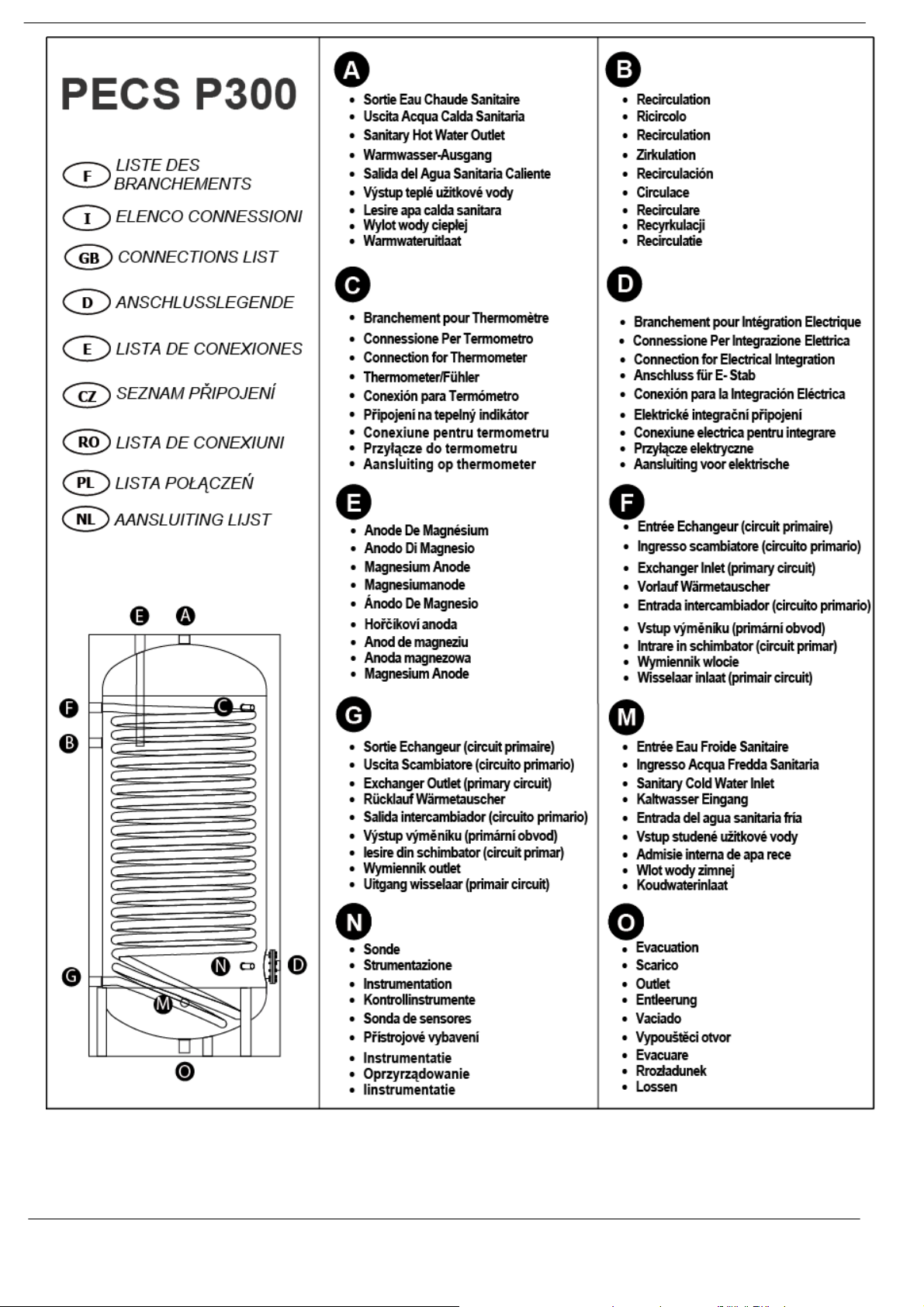
Liste des brachements …..…………………………………………………………………… 4
Schema indicatif de l’installation …...………………………………………………………….. 5
NOTICE D’EMPLOI – Ballon ………………………………………………………………….. 6
1. Généralités ........................................................................................................... 6
1.1 Identification de la catégorie …………………………………………………… 6
2. Installation et Entretien ……………………………………………………………….. 6
3. Branchements …………………………………………………………………………. 7
4. Service …………………………………………………………………………………. 7
5. Elimination 7
6. RÉCHAUFFEURS ÉLECTRIQUES MONOPHASÉS AVEC THERMOSTAT …… 7
6.1 Caractéristiques techniques ...…………………………………………………. 7
6.2 Installation ………………………………………………………………………. 7
6.3 Procédure d'installation ………………………………………………………… 8
6.4 Conditions d'utilisation …………………………………………………………. 8
6.5 Entretien ………………………………………………………………………… 8
6.6 Élimination du produit ………………………………………………………….. 8
Pièces détachées ………………………………………………………………………………. 8
- 2 - Notice d’utilisation “1577 – FR”
Page 3
PECS P300
Conditions limite de fonctionnement
ECHANGEUR ACCUMULATION
Pmax 12 bar Pmax 10 bar
Tmax 110 °C Max temp 90 °C
Données techniques
Conditions de Test standard
Vol. Net D'accumulation
[l] [l] [m2] [kWh/24h ]
291 27.9 3.4 1.87
Volume échangeurs
Superficie échangeurs
ars
EN 12897:2006 (65/20°C)
Chaleur dispersée
Rendement echangeurs
Norme de référence EN 12897:2006
∆P primaire échangeur Conditions de Test
PECS
Capacitè
[l] ∆P [mbar] [kW ] [m3/h ]
300 17,4
Echangeur
EN 12897:2006 (80/15-60-40°C)
Puissance échangeurs
35.2 1.4
Débit primaire
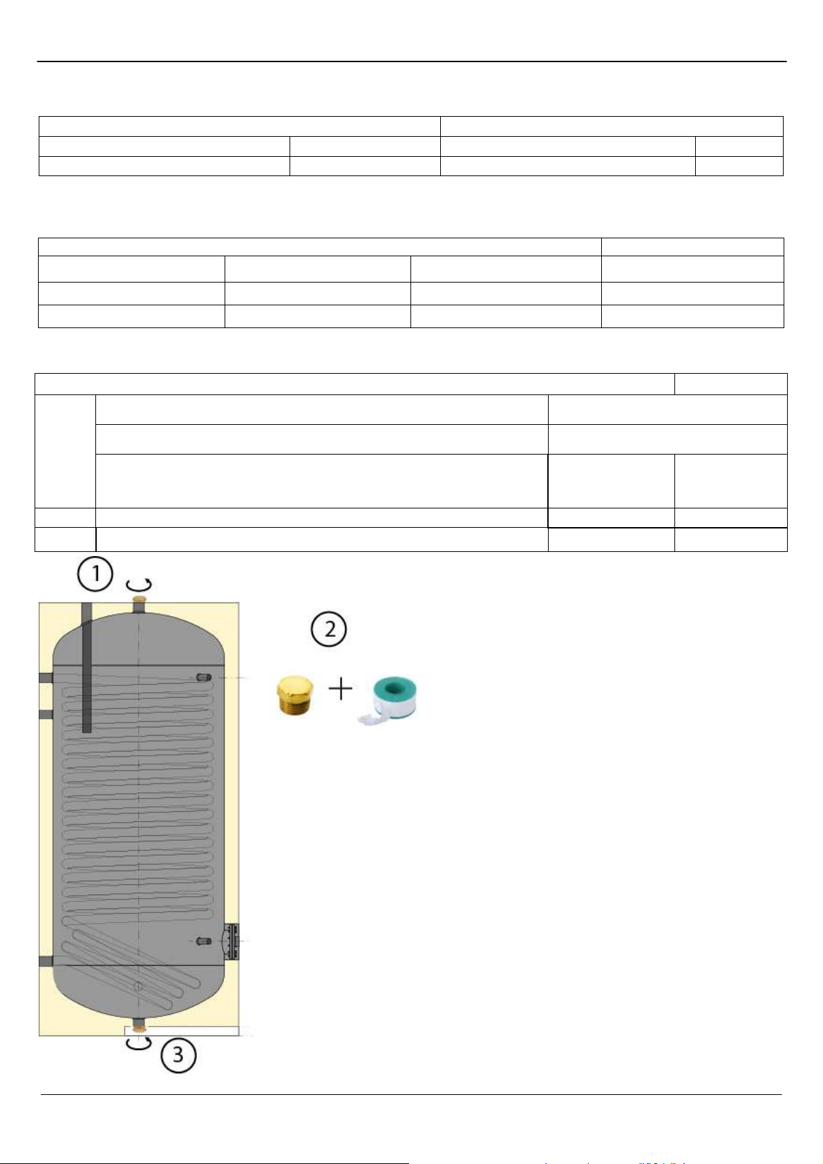
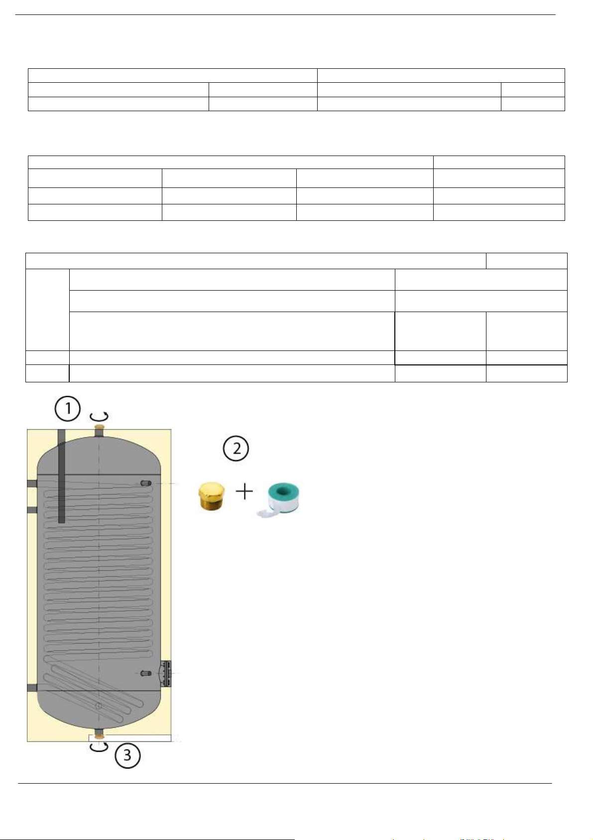
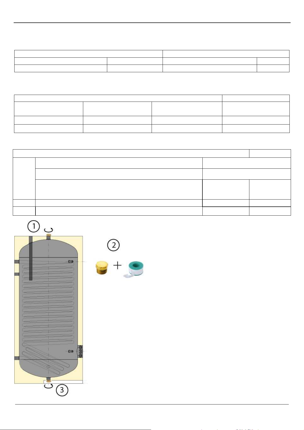
Il est prévu un capuchon, positionné sur la
partie supérieure du ballon, utilisable pour
fermer la connexion de décharge inférieure
- 3 - Notice d’utilisation “1577 – FR”
Page 4

PECS P300
Attention : les piquages ne sont pas bouchés de façon étachées à la livraison. Prévoir des bouchons pour ceux
non utilisés.
- 4 - Notice d’utilisation “1577 – FR”
Page 5
PECS P300
(Optional
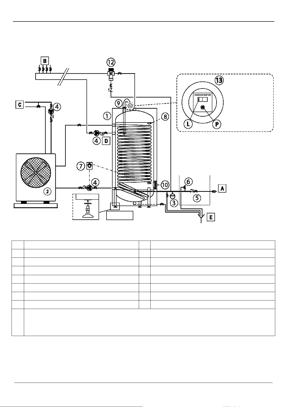
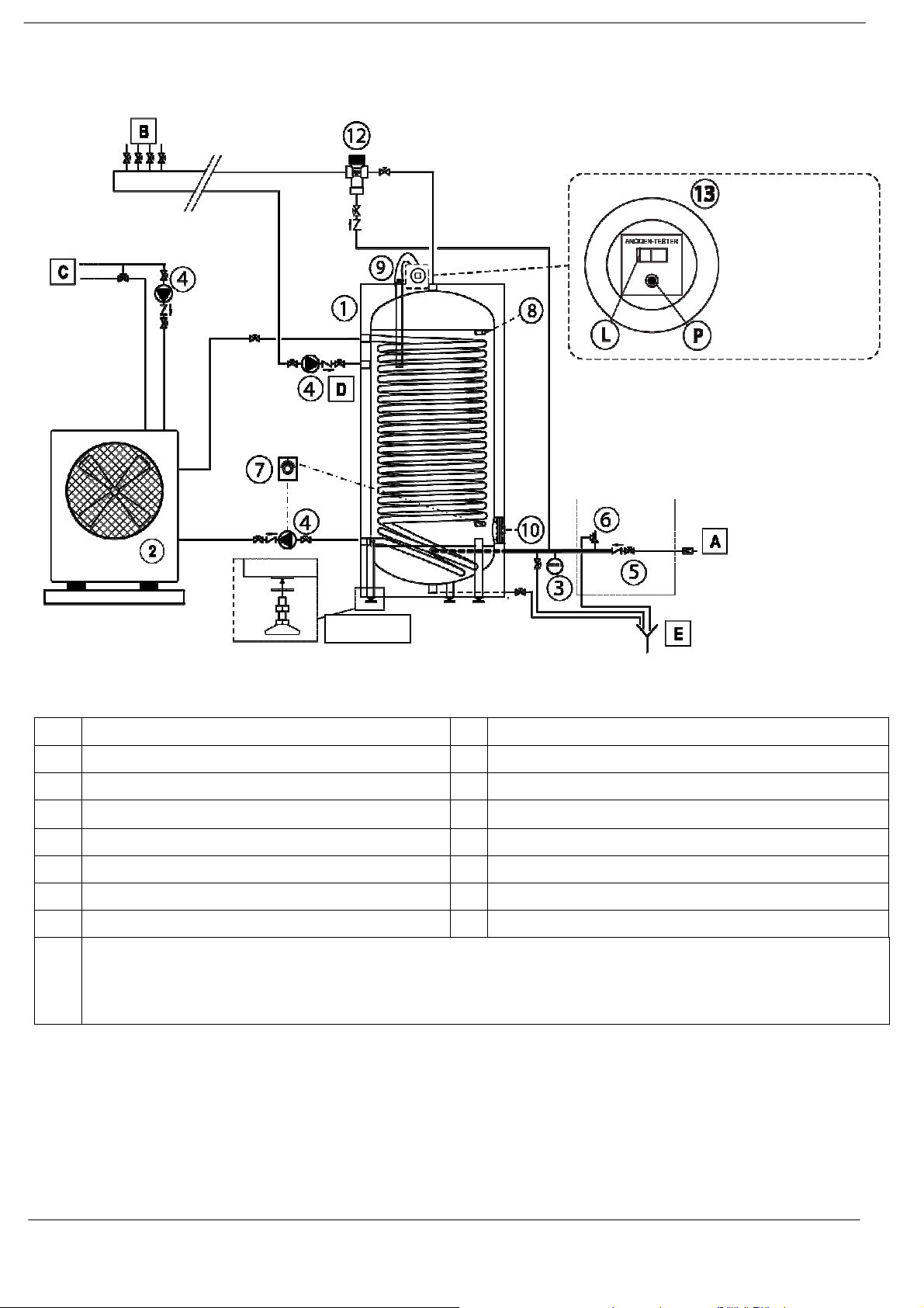
SCHEMA INDICATIF DE L’INSTALLATION
PECS
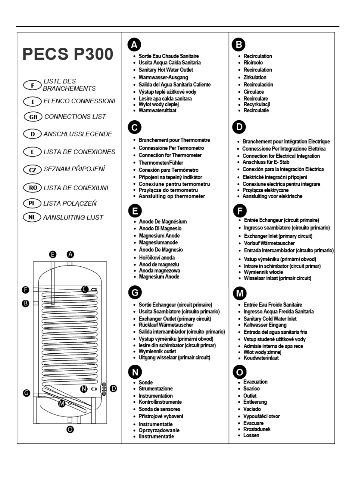
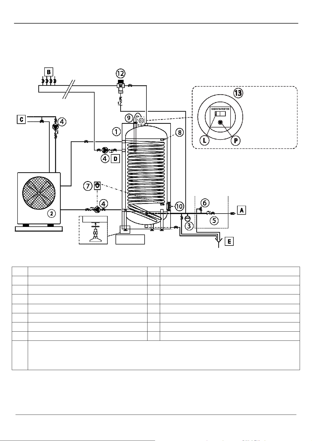
LEGENDE
A Entrée eau sanitaire 4 Groupe circulateur
B Connexions eau chaude sanitaire 5 Groupe de sécurité
C A l’installation de 6 Clapet de sécurité
D Circulación 7 Thermostat
8 Thermomètre
1 Ballon 9 Anode de magnésium
2 Générateur thermique 10 Eventuelle résistance
3 Vase d’expansion 12 Mélangeur thermostatique
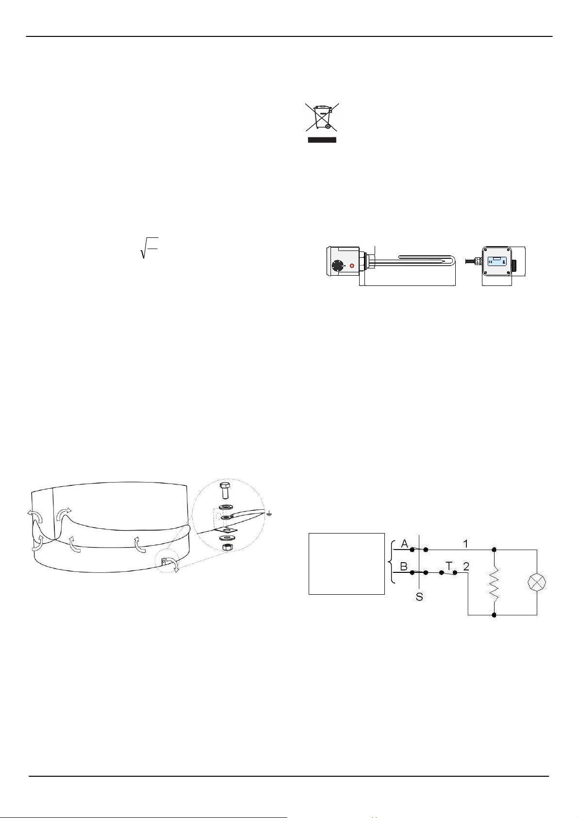
Dispositif Anoden Testeur permet de vérifier l'efficacité de l'anode de magnésium.
En pressant la touche P l'indicateur L se positionnera dans la zone de couleur verte en cas de
13
bon fonctionnement de l'anode. Si l'indicateur devait rester dans la zone rouge, l'anode doit être
contrôlé et, au besoin, remplacé.
- 5 - Notice d’utilisation “1577 – FR”
Page 6
PECS P300
NOTICE D’EMPLOI Ballons
1. Généralités
Le présent document est destiné à l’installateur et à l’utilisateur
final. Par conséquent, après l’installation et la mise en service de
l’installation, s’assurer qu’il est remis à l’utilisateur final ou au
responsable de la gestion de l’installation.
Les ballons de la société Atlantic ont été conçus et réalisés pour la
production et l’accumulation de l’eau chaude sanitaire par
l’échange thermique obtenu à l’aide d’échangeurs dédiés aux
ballons alimentés par des sources d’énergie thermique de
différents types (Générateur thermique, Pompe de chaleur,
Panneau solaire) qui utilisent l’eau comme fluide caloporteur.
Toute utilisation du produit autre que celle indiquée dans le
présent document libère le constructeur de toute responsabilité et
annulera toute forme de garantie.
Les produits qui font l’objet du présent document ont été fabriqués
selon la directive 97/23/CE (PED) relative aux appareils à pression
en relation avec le contenu et aux conditions de fonctionnement
prévues pour l’utilisation.
1.1 Identification de la catégorie
(Norme spécifique EN 12897:2006 - Directive 97/23/CE )
(Norme spécifique EN 12897:2006 - Directive 97/23/CE )
Les Ballons de la gamme PECS sont fabriqués dans le respect de
la norme spécifique EN 12897:2006 et il a sont testés selon les
dispositions de cette norme.
La gamme complète des ballons Atlantic possède des valeurs
inférieures à celles des seuils indiquées ci-après:
• Récipient destiné à contenir de l’eau (groupe 2) avec une tension
de vapeur à la température maximale admissible inférieure à 0,5
bars outre la pression atmosphérique normale (1033 mbars), la
pression maximale de service PS > 10 bars, le produit PS x V >
10.000 [bars x L], PS > 1000 bars;
•Tuyauteries destinées à contenir de l’eau (groupe 2) avec une
tension de vapeur à la température maximale admissible inférieure
à 0,5 bars outre la pression atmosphérique normale (1033 mbars),
la pression maximale de service PS > 10 bars, un diamètre DN >
200 et un produit PS x DN < 5000 [bar x mm].
Par conséquent, tous les ballons de la gamme Atlantic, selon l’Art.
3.3, et le contenu dans l’annexe II sur les tableaux 4 et 5, ne
doivent pas être marqués CE. Toutefois la société Atlantic S.r.l.
garantit pour ces appareils, conformément à la directive, une
fabrication correcte (selon le Système Environnement & Qualité
d’entreprise UNI EN ISO 9001:2000 – UNI EN 14001:2004) qui en
atteste une utilisation sûre et la détermination du constructeur.
En cas d’utilisation avec des systèmes solaires thermiques ou
autres installation utilisant une température supérieure à 110°
dans le circuit primaire, il est conseillé de dimensionner
l’installation de façon à ce que :
− La température du circuit primaire ne dépasse jamais 140°c et
seulement pour des temps limités
− La pression maximale de service respecte la limitation suivante.
Le produit de la pression par le volume de l’échangeur ne doit
pas dépasser 50 bar litres soit
P·V ≤ 50 [bar·l]
Donc, en tenant compte du fluide de l’échangeur, il est possible de
calculer la pression maximale admissible pour chaque serpentin.
Au-délà de ces limites, l’échangeur ainsi que l’installation sont
soumis aux prescriptions et normes en vigueur ou usage sur les
appareils à pression. Il est donc nécessaire que ceux-ci soit
projetés et contrôlés selon la norme 97/23/CE PED.
2. Installation et Entretien
Les ballons doivent toujours être installés à l’abri des agents
atmosphériques, sur une embase d’une solidité appropriée, en
vérifiant, avant d’effectuer les branchements, qu’il existe un
espace suffisant pour l’extraction de l’échangeur, de l’anode de
magnésium, et de l’éventuelle résistance.
• Si le local dans lequel se trouve le ballon ou le tuyauterie est
soumis à des températures inférieures à 0° durant c ertaines
périodes de l’année. il est nécessaire de prévoir un système de
protection contre le gel. A titre d’exemple un contrôle de
température stable du local ou la programmation de cycle de
chauffe soit par le générateur ou par la résistance d’appoint (qui
est optionnelle).
• Relativement aux capacités de 150 à 500 litres pour un juste
nivèlement du ballon réchauffeur, utiliser les pieds spéciaux
réglables (en OPTION) en combinaison avec les rondelles, en
ayant soin de serrer les contre-écrous prévus à cet effet (voir la
pièce sur les schémas). Pour éviter la rupture du calorifugeage,
soulever le ballon réchauffeur du sol à l’aide des écarteurs qui
s’appuient sur les trois pieds.
• Vérifier que les locaux destinés à l’installation des ballons
possèdent des dimensions en mesure de permettre le libre
passage desdits ballons vers l’extérieur sans qu’il ne faille avoir
recours à des démolitions de tout type que ce soit. La garantie ne
couvre pas d’éventuels coûts dérivant des manquements au
présent point.
• S’assurer que le lieu de l’installation du ballon est doté d’un
système de drainage (évacuation) adéquat au volume du ballon et
d’autres éventuels appareils. La garantie ne couvre pas
d’éventuels coûts dérivant des manquements au présent point.
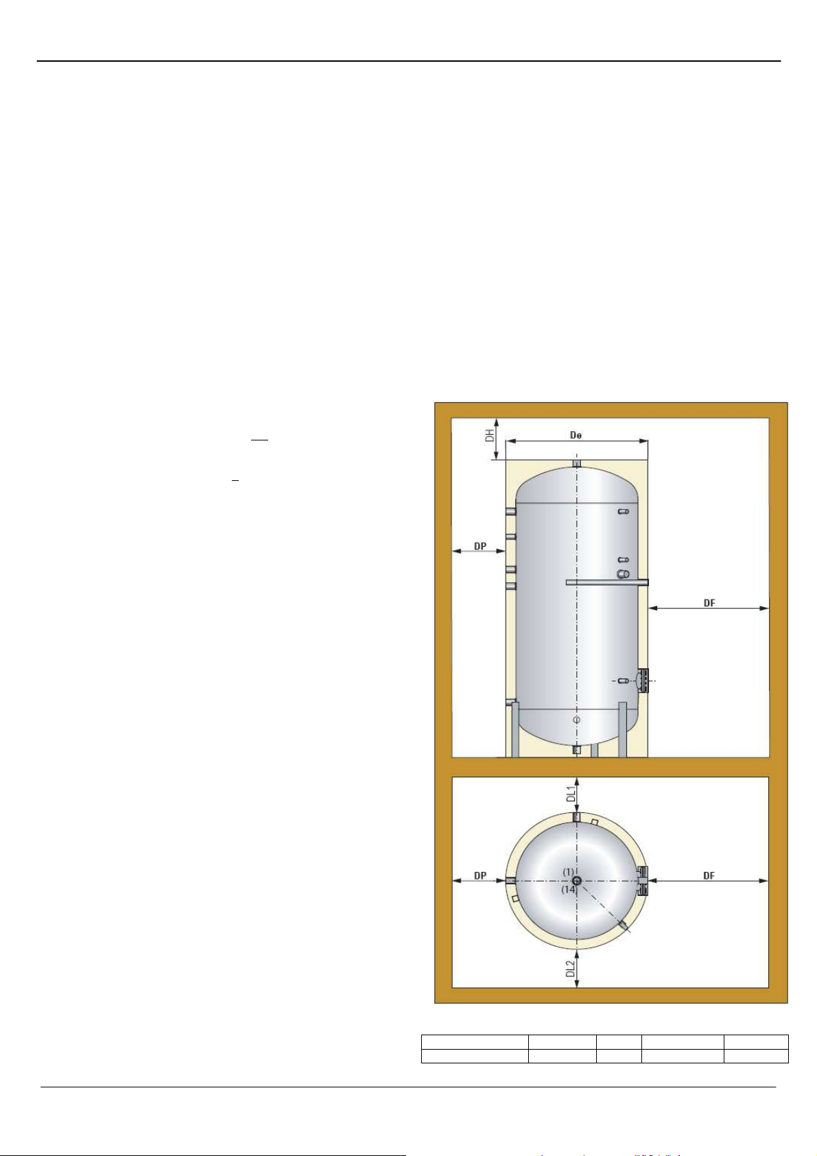
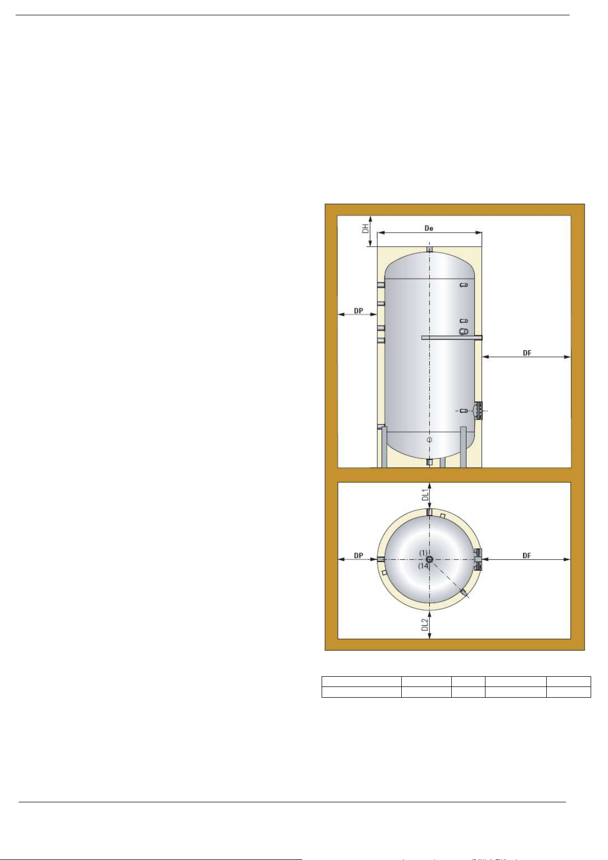
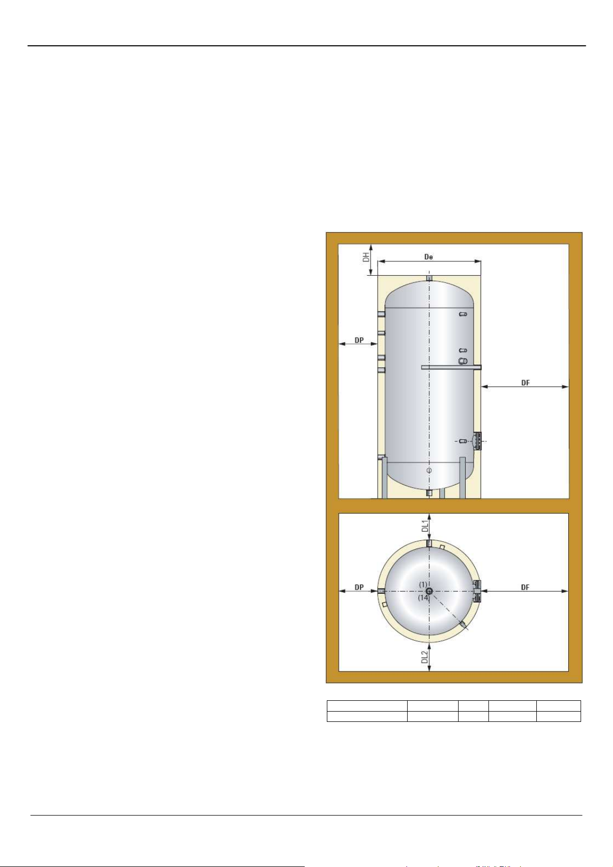
• Distances minimum:
Ballon DH DF DP = DL1 DL2
PECS 300 lt 700 mm = De 400 mm 200 mm
- 6 - Notice d’utilisation “1577 – FR”
Page 7
PECS P300
• Lors de la phase de manutention des appareils dont le poids est
supérieur à 30 kg, se servir d’engins de levage et de transport
adéquats. Pour cela les récipients doivent être manutentionnés
exclusivement à vide, au moyen de plates-formes spéciales ou de
chevilles de levage.
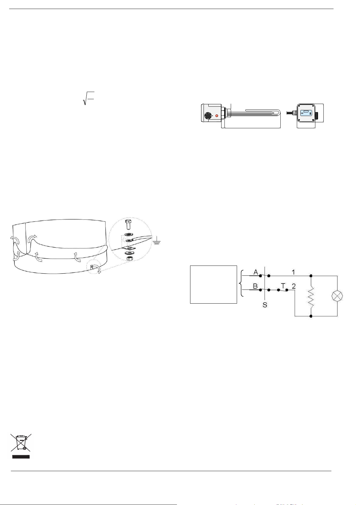
• Vérifier au cours de l’installation la présence d’anodes de
magnésium et vérifier la continuité électrique avec le réservoir (en
particulier pour l'anode sans fil de masse).
• L’installation et l’utilisation de l’appareil faisant l’objet des
présentes instructions doit toujours respecter les normes et les
règlements nationaux et locaux du lieu de l’installation.
Notamment le branchement de l’arrivée de l’eau froide sanitaire au
réseau hydrique domestique doit avoir lieu au moyen d’un groupe
de sécurité hydraulique conforme à la norme EN 1487:2002,
comprenant au moins un robinet d’arrêt, une vanne de retenue, un
dispositif de contrôle de la vanne de retenue, un dispositif
d’interruption de chargement hydraulique, un clapet de sécurité
dont l'orifice, sauf indication contraire de la loi en vigueur dans le
Pays d'installation, doit avoir un diamètre en millimètres non
inférieur à :
V
5
le volume en litres du ballon étant V, avec un minimum de 15 mm.
Le clapet devra être taré à une pression non supérieure à la
pression maximum de fonctionnement du ballon et relié sans
organes d'interception.
Prévoir un système d’expansion adéquat soit du côté chauffage
soit du côté sanitaire. Même quand les normes et les règlements
locaux prévoient que ce système d’expansion peut être constitué
seulement d’un clapet de sécurité dimensionné de façon approprié
, il est conseillé d’installer un vase d’expansion du type fermé à
membrane atoxique même pour éviter des ouvertures continuelles
du clapet de sécurité et pour ne pas surcharger inutilement le
ballon.
• Si l’installation de l’eau sanitaire dépasse les valeurs admissibles
de pression du ballon, installer un réducteur de pression à une
distance appropriée du ballon pour ne pas surchauffer ledit
réducteur de pression.
• En général dans les installations de production d’eau chaude
sanitaire, s’en tenir aux normes et aux règlementations locales sur
les traitements de l’eau en fonction de ses caractéristiques. La
garantie ne couvre pas les dommages déviant des manquements
aux prescriptions susmentionnées.
• Ne pas oublier que les appareils doivent toujours être branchés à
la terre.
entendues comme les températures maximales de résistance du
revêtement interne des ballons. Nous rappelons que la
température maximale d’utilisation doit respecter les normes
nationales sur la limitation des consommations énergétiques.
5. Elimination
A la fin du cycle de vie technique du produit, ses
composantes métalliques doivent être cédées à des
opérateurs autorisés à la collecte des matériaux
métalliques finalisées au recyclage tandis que les
composants non métalliques doivent être remis aux
opérateurs autorisés à leur élimination.
Les produits doivent être gérés, s’ils sont éliminés par le client
final, comme les déchets urbains et, par conséquent,
conformément aux règlements communaux de la commune
d’appartenance. En tout cas il ne doit pas être géré comme un
déchet domestique.
6. RÉCHAUFFEURS ÉLECTRIQUES
MONOPHASÉS AVEC THERMOSTAT
6.1 Caractéristiques techniques
Les réchauffeurs électriques d'immersion avec thermostat de
réglage et de sécurité seront utilisés comme source auxiliaire de
chauffage à l'intérieur des ballons (préparateurs d'eau chaude
sanitaire à accumulation). Le constructeur décline toute
responsabilité pour les dommages matériels et corporels
imputables à des utilisations impropres de l'appareil ou pour des
installations non conformes aux présentes instructions.
Caractéristiques techniques
Réchauffeurs électriques utilisables comme intégration sur les
ballons, fournis avec le thermostat de réglage, le thermostat de
sécurité à réarmement manuel et 2 m de câble électrique câblé et
sans fiche
4
0
50
30
0
6
°C
70
Éléments chauffants en acier inoxydable AISI-316L
Classe de protection IP 65
Thermostat de réglage de 30 °C à 70 °C et thermosta t de
sécurité à réarmement manuel à 90 °C
Bouton de réglage
Voyant lumineux rouge pour indiquer le fonctionnement de la
résistance
Câble d'alimentation sans fiche en PVC noir 3Gx1,5.
R
18.5
L
SCHÉMA ÉLECTRIQUE
LOGO
IP65
IP65
IP65IP65
VOLT - WATT
VOLT - WATT
VOLT - WATTVOLT - WATT
103
103
Alimentation
résistance dans
module
• La consommation progressive de l’anode de magnésium peut
hydraulique PAC
varier selon les conditions opérationnelles et la nature de l’eau.
Programmer, au début, des contrôles fréquents de l’anode de
magnésium pour en vérifier l’état de consommation et en
organiser le remplacement périodique au moins une fois par an.
• Au moment de la mise en marche et après quelques jours de
fonctionnement, vérifier le serrage des boulons de la bride de
l’échangeur, facilement accessibles grâce aux couvercles couvrebride amovibles.
3. Branchements
Le schéma de branchement aux installations indiqué sur cette
feuille s’entend à titre purement indicatif et non contraignant car
c’est à l’auteur du projet de l’installation sur laquelle sera monté le
ballon, qu’il incombe d’évaluer, conformément aux normes
d’installation en vigueur, le meilleur schéma de l’installation pour
son utilisation conformément aux limites imposées par les
données déclarées par le constructeur.
4. Service
Les températures maximales de service indiquées dans le présent
document et sur la plaque des données de l’appareil doivent être
Le thermostat doit être régler sur 70°C
6.2 Installation
L'installation du réchauffeur électrique doit être effectuée,
conformément aux instructions, par un professionnel ayant
les qualifications requises en fonction des normes en vigueur
afin d'éliminer toute condition de risque.
Avant d'effectuer l'installation, n'oubliez pas de couper
l'alimentation électrique.
Vérifiez l'intégrité de toutes les parties de l'appareil et la
correspondance de la fourniture de série des équipements
(joint et câble d'alimentation) ; ne jamais modifier les pièces
de la résistance et éviter d'empiler les poids même emballés.
Vérifiez que la tension d'alimentation à laquelle vous
brancherez le réchauffeur soit conforme à celle imprimée sur
- 7 - Notice d’utilisation “1577 – FR”
Page 8
PECS P300
la résistance (± 10 %) et que le circuit d'alimentation
électrique réponde aux normes en vigueur
Vérifiez que les câbles de la ligne aient la juste dimension en
fonction de la puissance
Assurez-vous que l'installation soit équipée du branchement
à la terre.
Ne courbez pas la résistance et assurez-vous que l'espace
disponible à l'intérieur et à l'extérieur du réservoir soit
compatible avec les dimensions et les encombrements pour
le montage du réchauffeur.
Le réchauffeur doit être monté de façon à ce que la
résistance soit en position horizontale et toujours
entièrement immergée, de préférence dans la partie basse
du réservoir pour un meilleur échange thermique.
Le réchauffeur ne doit absolument pas être allumé si la
résistance n'est pas entièrement immergée.
Évitez l'installation du ballon dans des zones où peuvent se
présenter des sédimentations.
Branchez le réchauffeur au réseau électrique en interposant
un instrument d'interruption des caractéristiques
appropriées.
Le circuit d'alimentation électrique de l'appareil doit être
protégé par un interrupteur différentiel (disjoncteur) à haute
sensibilité (30 mA max).
Lors du branchement électrique, respecter les couleurs de
chaque conducteur :
jaune-vert → terre
autres couleurs → phases.
6.4 Conditions d'utilisation
Respectez les éventuelles normes relatives à la température
maximale de stockage de l'eau chaude sanitaire.
Le réchauffeur doit être utilisé dans les limites de températures
indiquées ci-dessus (et jamais avec des températures supérieures
à 100 °C) et uniquement pour chauffer l'eau potable, sans
impuretés ou éléments polluants et avec une dureté comprise
entre 7 et 25 °f . Si la valeur de la dureté de l'eau est supérieure,
installez un adoucisseur sur l'installation ou prévoyez le nettoyage
périodique de la résistance, en faisant attention de ne pas
l'endommager ; en revanche, en présence d'impureté, prévoyez
des filtres en amont de l'accumulation.
Assurez-vous que l'environnement dans lequel est installée la
résistance réponde aux conditions suivantes :
Température ambiante comprise entre 5 °C et 45 °C e t humidité ≤
0,015 kg d'eau par kg d'air sec (voir tableau).
Température 0 °C 20 °C 30 °C 40 °C 50 °C
Humidité relative
max 100 % 100 % 60 % 33 % 20 %
Positionnement éloigné de sources de chaleur et dans une zone
bien aérée
6.5 Entretien
Toutes les opérations d'installation, de câblage et de
contrôle doivent être effectuées après avoir coupé
l'alimentation électrique.
En cas d'intervention du thermostat de sécurité, effectuez un
contrôle de l'installation par un opérateur qualifié avant
d'effectuer le réarmement manuel du thermostat.
Si le câble d'alimentation s'avère endommagé, le faire
remplacer par un électricien qualifié.
6.6 Élimination du produit
À la fin de leur cycle de vie, le produit et ses composants
métalliques doivent être remis à des centres de tri autorisés pour
le recyclage des matériaux métalliques alors que les composants
non métalliques doivent être remis à des centres autorisés à leur
recyclage. Si les produits sont éliminés par le client final, ils
doivent être gérés comme des déchets urbains suivant les
règlements communaux du lieu d'appartenance. Dans tous les
cas, ils ne doivent pas être traités comme des déchets
domestiques.
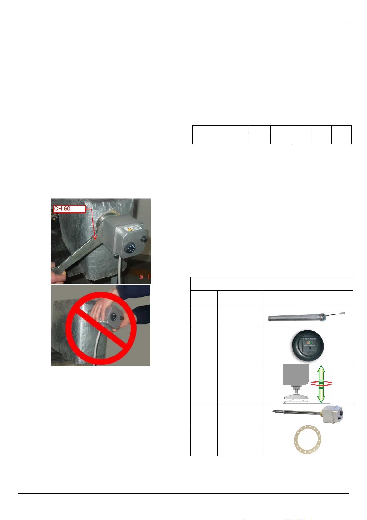
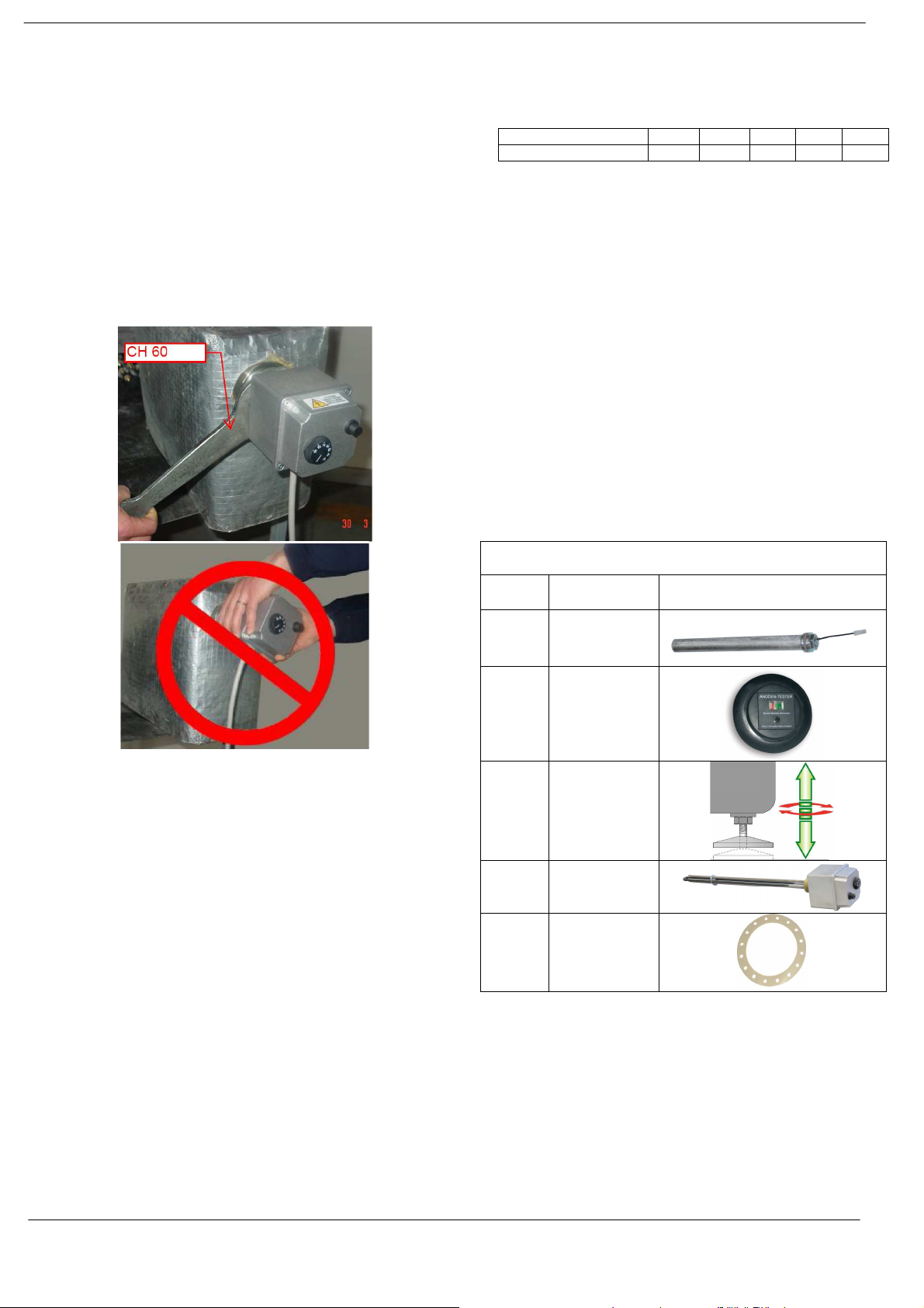
Pièces détachées
Code Désignation Image
100393 Anode
100394 Anode test
6.3 Procédure d'installation
Positionnez le joint.
Engagez le réchauffeur dans la connexion du ballon indiquée
par le constructeur de celui-ci ; dans le cas de connexion
disponible de diamètre supérieur, l'utilisation d'une réduction
est admise (utilisez des réductions en acier ou en fonte,
éviter les éléments en laiton, en cuivre ou tout autre matériel
à potentiel électrique élevé). Évitez que la connexion soit au
total plus longue de 100 mm.
Serrez le réchauffeur avec une clé appropriée en appliquant
un couple ne dépassant pas les 10 kg.m ; pour le serrage,
NE PAS appliquer de torsion au conteneur externe du
réchauffeur.
Procédez au remplissage du ballon pour vérifier l'étanchéité
hydraulique du branchement.
Procédez au branchement électrique en suivant les
avertissements décrits ci-dessus.
Réglez le thermostat à la température désirée.
- 8 - Notice d’utilisation “1577 – FR”
160708 Pieds réglables
160708 Résistence
142898 Joint
Page 9
PECS P300
Sommario
____________________________________________________________________________________
Condizioni limite di esercizio ………….……………………………………………………...... 10
Dati tecnici ………………………………………….……………………………………………. 10
Prestazioni scambiatori ……………………………….……………………………………...... 10
Elenco connessioni ……..……………………………………………………………………… 11
SCHEMA INDICATIVO DI INSTALLAZIONE .….………………………………………….. 12
MANUALE D’USO Bollitore ...………………………………………………………………….. 13
1.Generalità …........................................................................................................... 13
1.1 Identificazione della categoria ………………………………………………… 13
2. Installazione e Manutenzione …..…………………………………………………….. 13
3. Connessioni ……………………………………………………………………………. 14
4. Esercizio ………………………………………………………………………………… 14
5. Smaltimento …………………………………………………………………………….. 14
6. RISCALDATORI ELETTRICI MONOFASE CON TERMOSTATO ………………... 14
6.1 Caratteristiche tecniche …………………………………………………………. 14
6.2 Installazione………………………………………………………………………. 14
6.3 Procedura di installazione……………………………………………………….. 15
6.4 Condizioni di esercizio…………………………………………………………… 15
6.5 Manutenzione ……………………………………………………………………. 15
6.6 Smaltimento ……………………………………………………………………… 15
Ricambi ..…………………………………………………………………………………………. 15
- 9 - Návod k obsluze “1577 – IT”
Page 10
PECS P300
Condizioni limite di esercizio
SCAMBIATORE ACCUMULO
Pmax 12 bar Pmax 10 bar
Tmax 110 °C TMax 90 °C
Dati tecnici
Condizioni di prova
Vol. Netto Accumulo
[l]
291 27.9 3.4 1.87
Volume scambiatori
[l]
Superficie scambiatori
[m2] [kWh/24h ]
EN 12897:2006 (65/20°C)
Calore disperso
Prestazioni scambiatori
Norma di riferimento EN 12897:2006
∆P scambiatore su primario Condizioni di prova
Capacità
PECS
[l] ∆P [mbar] [kW ] [m3/h ]
300 17,4
Scambiatore Potenza scambiatori Flusso primario
EN 12897:2006 (80/15-60-40°C)
35.2 1.4
Viene fornito un tappo, posizionato sulla
parte superiore del bollitore, utilizzabile per
chiudere la connessione di scarico
inferiore
- 10 - Notice d’utilisation “1577 – IT”
Page 11
PECS P300
Attenzione: le connessioni non sono tappate a tenuta all’atto della consegna. Prevedere tappi per le
connessioni non utilizzate.
- 11 - Notice d’utilisation “1577 – IT”
Page 12
PECS P300
(Optional
SCHEMA INDICATIVO DI INSTALLAZIONE
PECS
LEGENDE - LEGENDA - KEY - LEGEND - LEYENDA - VYSVĚTLIVKY – LEGENDA – LEGEND -
LEGEND
A Ingresso acqua sanitaria 4 Gruppo circolatore
B Utenze acqua calda 5 Gruppo di sicurezza
C All’impianto di riscaldamento 6 Valvola di sicurezza
D Ricircolo 7 Termostato
8 Termometro
1 Bollitore 9 Anodo di magnesio
2 Generatore termico 10 Eventuale resistenza elettrica
3 Vaso di espansione 12 Miscelatore termostatico
Dispositivo Anoden Tester consente di verificare l’efficienza dell’anodo di magnesio.
Premendo il tasto P l’indicatore L si posizionerà nella zona di colore verde in caso di corretto
13
funzionamento dell’anodo. Se l’indicatore dovesse rimanere nella zona rossa, l’anodo va
controllato ed eventualmente sostituito.
- 12 - Notice d’utilisation “1577 – IT”
Page 13
PECS P300
MANUALE D’USO Bollitore
1.Generalità
Il presente documento è destinato all’installatore ed all’utilizzatore
finale. Pertanto dopo l’installazione e l’avvio dell’impianto occorre
assicurarsi che esso sia consegnato all’utilizzatore finale o al
responsabile della gestione dell’impianto.
I bollitori dell’azienda Atlantic sono stati progettati e realizzati per
essere utilizzati nella produzione ed accumulo di acqua calda
igienico-sanitaria attraverso lo scambio termico ottenuto con l’ausilio
di scambiatori estraibili, fissi o esterni al bollitore alimentati da fonti di
energia termica di vario tipo (Generatore termico, Pompa di calore,
Pannello solare) che utilizzino acqua come fluido termovettore.
Ogni utilizzo del prodotto diverso da quello indicato nel presente
documento solleva il costruttore da ogni responsabilità e comporta il
decadimento di ogni forma di garanzia.
I prodotti oggetto del presente documento sono stati costruiti in
ottemperanza alla direttiva 97/23/CE (PED) relativa agli apparecchi a
pressione in relazione al fluido contenuto ed alle condizioni di
esercizio contemplate per l’utilizzo.
1.1 Identificazione della categoria (Specifica EN 12897:2006 Direttiva 97/23/CE)
I Bollitori della gamma PECS sono realizzati nel rispetto della
specifica EN 12897:2006 e sono stati testati secondo le disposizioni
di tale norma.
La gamma completa di bollitori Atlantic ha valori inferiori a quelli di
soglia riportati di seguito:
• Recipiente destinato a contenere acqua (gruppo 2) con una
tensione di vapore alla temperatura massima ammissibile inferiore a
0,5 bar oltre la pressione atmosferica normale (1033 mbar),
pressione massima di esercizio PS > 10 bar, prodotto PSxV > 10.000
[bar x L], PS > 1000 bar;
•Tubazioni destinate a contenere acqua (gruppo 2) con una tensione
di vapore alla temperatura massima ammissibile inferiore a 0,5 bar
oltre la pressione atmosferica normale (1033 mbar), pressione
massima di esrcizio PS > 10 bar, diametro DN > 200 e prodotto PS x
DN < 5000 [bar xmm].
Pertanto tutti i bollitori e i relativi scambiatori della gamma Atlantic
non devono essere marcati CE, secondo quanto si legge nell’ Art. 3.3
e riportato nell’allegato II tabelle 4 e 5. Per essi La Atlantic S.r.l.
garantisce, come stabilito dalla direttiva, una corretta prassi
costruttiva (secondo il Sistema Ambiente & Qualità aziendale UNI EN
ISO 9001:2000 – UNI EN 14001:2004) che ne assicura la sicurezza
di utilizzazione e la individuazione del costruttore.
Per l’utilizzo degli scambiatori in sistemi solari termici (o altra tipologia
di impianto) che prevedano una temperatura > 110°C nel circuito
primario, si raccomanda di dimensionare l’impianto in modo tale che:
− La temperatura del circuito primario non superi mai la temperatura
di 140°C (che può essere raggiunta solo per periodi di tempo
limitati).
− La Pressione massima di esercizio rispetti la seguente limitazione: Il
prodotto Pressione per Volume dello scambiatore non deve
superare 50 bar·litro, ovvero
P·V ≤ 50 [bar·l]
Dato il volume di fluido nello scambiatore è quindi possibile calcolare,
con la formula sopra riportata, la pressione massima di esercizio
ammissibile per ciascuno scambiatore.
Oltre tali limiti lo scambiatore (come l’impianto) è soggetto alle
prescrizioni previste per attrezzature in pressione (progettazione,
verifiche all’impianto ed in esercizio, riqualificazioni periodiche etc), è
quindi necessario utilizzare scambiatori progettati e collaudati
secondo normativa 97/23/CE PED.
2. Installazione e Manutenzione
I bollitori vanno sempre installati al riparo dagli agenti atmosferici, su
basamento di adeguata solidità, verificando, prima di effettuare i
collegamenti, che vi sia spazio sufficiente per l’estrazione dello
scambiatore, dell’anodo di magnesio, dell’eventuale resistenza.
• Se in periodi dell’anno, il locale in cui è installato il bollitore o le
tubazioni sono soggette a temperature < 0°C, è necessario prevedere
adeguati sistemi di protezione contro il gelo, quali, a mero titolo di
esempio, la termostatizzazione dei locali o la programmazione di cicli
di riscaldamento tramite il generatore o la resistenza ausiliaria (non in
dotazione).
- 13 - Návod k obsluze “1577 – IT”
• Relativamente alle capacità da 150 a 500 litri, per il corretto
livellamento del bollitore occorre utilizzare gli appositi piedini
regolabili (OPTIONAL) avendo cura di serrare gli appositi controdadi
(vedi particolare negli schemi). Per evitare la rottura della
coibentazione, sollevare il bollitore da terra tramite distanziatori che
poggino su tutti e tre i piedi.
• Verificare che i locali destinati all'ubicazione dei Bollitori abbiano
aperture di dimensioni tali da consentire il libero passaggio degli
stessi verso l'esterno senza che vi sia la necessità di operare
demolizioni di alcun genere. La garanzia non copre eventuali costi
derivanti da inadempienze al presente punto.
• Assicurarsi che il locale di installazione del bollitore sia dotato di un
sistema di drenaggio (scarico) adeguato al volume del bollitore e di
altri eventuali apparecchi. La garanzia non copre eventuali costi
derivanti da inadempienze al presente punto.
Distanze minime:
Serbatoio DH DF DP = DL1 DL2
PECS 300 lt 700 mm = De 400 mm 200 mm
• La fase di movimentazione degli apparecchi il cui peso ecceda i 30
kg richiede l’ausilio di idonei mezzi di sollevamento e trasporto. Per
questo scopo i recipienti vanno movimentati, esclusivamente a vuoto,
per mezzo delle apposite pedane o golfari di sollevamento.
• Verificare in sede di installazione la presenza di anodi di magnesio e
controllare la continuità elettrica col serbatoio (in particolare per gli
anodi non dotati di filo di massa).
• Sulla base di quanto dettato dalla Circolare Ministeriale n. 829571
del 23/03/03 l’istallazione alla rete idrica domestica dei bollitori deve
•
Page 14
PECS P300
calore
avvenire tramite un gruppo di sicurezza idraulica, comprendente
almeno un rubinetto di intercettazione, una valvola di ritegno, un
dispositivo di controllo della valvola di ritegno, una valvola di
sicurezza, un dispositivo di interruzione di carico idraulico, tutti
accessori necessari ai fini dell'esercizio in sicurezza dei bollitori
medesimi.
• Prevedere un sistema di espansione. In base a quanto previsto
dalla raccolta R fasc.R-1A per i riscaldatori d’acqua in cui la
temperatura del primario è inferiore o uguale a quella di ebollizione
del fluido secondario a pressione di 0.5 bar, tale sistema di
espansione può essere costituito semplicemente da una valvola di
sfogo, del tipo a contrappeso o a molla, il cui orifizio abbia un
diametro in millimetri non inferiore a:
V
5
essendo V il volume in litri del bollitore, con un minimo di 15 mm.
La valvola dovrà essere tarata ad una pressione non superiore a
quella massima di esercizio del bollitore e collegata senza organi di
intercettazione. Oltre alla valvola è tuttavia consigliabile, per evitare le
continue aperture della valvola stessa e per non sovraccaricare
inutilmente il bollitore, installare un vaso di espansione del tipo chiuso
a membrana atossica come indicato nello schema.
• Se l’impianto dell’acqua sanitaria supera i valori ammissibili di
pressione del bollitore installare un riduttore di pressione il più lontano
possibile dal bollitore stesso.
• In generale negli impianti di produzione di acqua calda sanitaria ci si
deve attenere a quanto disposto dalla norma UNI CTI 8065 che
prevede vari tipi di trattamenti dell’acqua in funzione delle sue
caratteristiche. La garanzia non copre danni derivanti da
inadempienze alle prescrizioni della norma UNI CTI 8065.
• Si ricorda che gli apparecchi vanno sempre elettricamente collegati
a terra.
I prodotti devono essere gestiti, se smaltiti dal cliente finale, come
assimilabili agli urbani pertanto nel rispetto dei regolamenti comunali
del comune di appartenenza. In ogni caso esso non va gestito come
un rifiuto domestico.
6. RISCALDATORI ELETTRICI MONOFASE
CON TERMOSTATO
6.1 Caratteristiche tecniche
I riscaldatori elettrici ad immersione con termostato di regolazione e
di sicurezza sono destinate ad essere utilizzate come fonte ausiliaria
di riscaldamento all’interno dei bollitori (preparatori di acqua calda
sanitaria ad accumulo). Il costruttore declina ogni responsabilità per
danni materiali o corporali riconducibili ad utilizzi impropri
dell’apparecchio o per installazioni non conformi alle presenti
istruzioni
Caratteristiche tecniche
Riscaldatori elettrici utilizzabili come integrazione sui bollitori, forniti
completi di termostato di regolazione, termostato di sicurezza a
riarmo manuale e 2 mt di cavo elettrico cablato e senza spina
4
0
50
30
0
6
°C
70
Elementi riscaldanti in acciaio inossidabile AISI-316L
Classe di protezione IP 65
Termostato di regolazione 30°C a 70 °C e termostato di
sicurezza a riarmo manuale 90°C
Manopola di regolazione
Spia luminosa rossa per indicare il funzionamento della
resistenza
Cavo di alimentazione senza spina in PVC nero 3G x 1,5.
R
LOGO
IP65
IP65
IP65IP65
VOLT - WATT
VOLT - WATT
VOLT - WATTVOLT - WATT
18.5
L
103
103
SCHEMA ELETTRICO
• Il progressivo consumo dell’anodo di magnesio può variare in base
alle condizioni operative ed alla natura dell’acqua.
Programmare inizialmente dei controlli frequenti dell’anodo di
magnesio per verificarne lo stato di consumo ed organizzarne la
sostituzione periodica almeno una volta l’anno.
• All’avviamento e dopo alcuni giorni di funzionamento, verificare il
serraggio dei bulloni della flangia dello scambiatore, facilmente
accessibili grazie alle coppelle copriflangia asportabili.
3. Connessioni
Lo schema di connessione agli impianti riportato su questo foglio si
intende puramente indicativo e non vincolante in quanto è fatto carico
al progettista dell'impianto su cui verrà installato il bollitore valutare,
nel rispetto delle norme di installazione vigenti, lo schema
impiantistico migliore per il suo utilizzo nel rispetto dei limiti imposti
dai dati dichiarati dal costruttore.
4. Esercizio
Le temperature massime di esercizio riportate sul presente
documento e sulla targa dati dell’apparecchio vanno intese come
temperature massime di resistenza del rivestimento interno dei
bollitori. Si ricorda che la temperatura massima di utilizzo deve
rispettare le norme sul contenimento dei consumi energetici. In Italia
si veda quanto dettato dalla Legge 10/91 e successivi decreti attuativi
ed integrativi.
5. Smaltimento
Alla fine del ciclo di vita tecnico del prodotto i suoi
componenti metallici vanno ceduti ad operatori
autorizzati alla raccolta dei materiali metallici finalizzata
al riciclaggio mentre i componenti non metallici vanno
ceduti ad operatori autorizzati al loro smaltimento.
Alimentazione
resistenza
elettrica dal
modulo idraulico
della pompa di
Il termostato deve essere regolato a 70 °C
6.2 Installazione
L’installazione del riscaldatore elettrico deve essere effettuata,
conformemente alle istruzioni, da un professionista avente la
necessaria qualifica in base alle normative vigenti in modo da
eliminare qualsiasi condizione di rischio.
Prima di effettuare l’installazione non dimenticare di staccare
l’alimentazione elettrica.
Verificare l’integrità dell’apparecchio in tutte le sue parti e la
corrispondenza della dotazione di serie degli accessori
(guarnizione e cavo di alimentazione) non manomettere o
modificare in alcun modo parti della resistenza ed evitare di
sovrapporre pesi anche imballata.
Controllare che la tensione di alimentazione alla quale si andrà
a collegare il riscaldatore sia conforme a quella stampigliata
sulla resistenza stessa (± 10%) e Il circuito di alimentazione
elettrica risponda alla normativa vigente
Verificare che i cavi della linea siano dimensionati in funzione
della potenza
Assicurarsi che l’impianto sia provvisto del collegamento a terra.
Non curvare la resistenza ed assicurarsi che lo spazio
disponibile all’interno ed all’esterno del serbatoio sia compatibile
- 14 - Notice d’utilisation “1577 – IT”
Page 15
PECS P300
con le dimensioni e gli ingombri per il montaggio del
riscaldatore.
Il riscaldatore va montato in modo che la resistenza risulti in
posizione orizzontale e sempre completamente immersa,
preferibilmente nella parte bassa del serbatoio per un migliore
scambio termico.
Il riscaldatore non deve assolutamente essere messo in
funzione se la resistenza non è completamente immersa.
Evitare l’installazione in zone del bollitore ove possano
verificarsi sedimentazioni.
Collegare il riscaldatore alla rete elettrica interponendo un
organo di interruzione di caratteristiche adeguate.
Il circuito di alimentazione elettrica del’apparecchio deve essere
protetto da un interruttore differenziale (salvavita) ad alta
sensibilità (30 mA max).
Nel collegamento elettrico rispettare i colori dei singoli
conduttori:
giallo-verde → terra
altri colori → fasi.
facendo attenzione a non danneggiarla in nessun modo; mentre in
presenza di impurità prevedere dei filtri a monte dell’accumulo.
Assicurarsi che l’ambiente in cui viene installata la resistenza
risponda alle seguenti condizioni:
Temperatura ambiente compresa fra i 5°C e 45 °C ed umidità ≤
0.015 kg di acqua per kg di aria secca (cfr tabella).
Temperatura 0°C 20°C 30°C 40°C 50°C
Max Umidità relativa 100% 100% 60% 33% 20%
Posizionamento lontano da fonti di calore e in zona ben aerata
6.5 Manutenzione
Tutte le operazioni di installazione, cablaggio e controllo devono
essere effettuate dopo aver disconnesso l’alimentazione
elettrica.
In caso di intervento del termostato di sicurezza occorre un
controllo dell’impianto da parte di operatore qualificato prima di
effettuare il riarmo manuale del termostato stesso.
Se cavo di alimentazione risulta danneggiato, esso va sostituito
a cura di un elettricista qualificato.
6.6 Smaltimento
Alla fine del ciclo di vita tecnico del prodotto i suoi componenti
metallici vanno ceduti ad operatori autorizzati alla raccolta dei
materiali metallici finalizzata al riciclaggio mentre i componenti non
metallici vanno ceduti ad operatori autorizzati al loro smaltimento. I
prodotti devono essere gestiti, se smaltiti dal cliente finale, come
assimilabili agli urbani pertanto nel rispetto dei regolamenti comunali
del comune di appartenenza. In ogni caso esso non va gestito come
un rifiuto domestico.
Ricambi
6.3 Procedura di installazione
Posizionare la guarnizione.
Avviare il riscaldatore nella connessione del bollitore indicata
dal costruttore dello stesso, in caso di connessione disponibile
di diametro superiore è ammesso l’uso di una riduzione
(utilizzare riduzioni in acciaio o ghisa, evitare elementi in ottone,
rame o altro materiale ad elevato potenziale elettrico). Evitare
che la connessione sia complessivamente più lunga di 100 mm.
Serrare il riscaldatore con una chiave idonea applicando una
coppia non superiore a di 10 kgm, per il serraggio NON
applicare torsioni al contenitore esterno del riscaldatore.
Procedere al riempimento del bollitore in modo da verificare la
tenuta idraulica del collegamento.
Procedere alla connessione elettrica seguendo le avvertenze di
cui sopra.
Regolare il termostato alla temperatura desiderata.
Codice Descrizione Immagine
100393 Anodo
100394 Anoden tester
160708 Piedi regolabili
160708 Resistenza
142898 Guarnizione
6.4 Condizioni di esercizio
Rispettare eventuali normative circa la massima temperatura di
stoccaggio delle’acqua calda sanitaria.
Il riscaldatore deve essere utilizzato entro i limiti di temperatura sopra
indicati (e mai con temperatura superiore a 100°C) ed
esclusivamente per riscaldare acqua potabile, priva di impurità o
elementi inquinanti e con durezza compresa tra 7 e 25°Fr . Nel caso
di durezza dell’acqua superiore è necessario installare un addolcitore
nell’impianto o prevedere la pulizia periodica della resistenza,
- 15 - Notice d’utilisation “1577 – IT”
Page 16

PECS P300
Table of Contents
________________________________________________________________________________
Operating limit conditions ………….………………………………………………….……...... 17
Technical data ………………………………….………………………………………….……. 17
Exchanger performance ……………………………….……………………………………..... 17
Connection list ……..…………………………………………………………………………… 18
INSTALLATION GUIDELINE DIAGRAM .….………………………………………………… 19
USER MANUAL Water heater …………………………………………………………………. 20
1. General ….............................................................................................................. 20
1.1 Category identification ………………………………………………………….. 20
2. Installation and maintenance …..……………………………………………………… 20
3. Connections …………………………………………………………………………….. 21
4. Operation ………………………………………………………………………………... 21
5. Disposal …………………………………………………………………………………. 21
6. SINGLE PHASE ELECTRIC HEATER WITH THERMOSTAT …………………….. 21
6.1 Technical features ………………………………………………………………. 21
6.2 Installation ………………………………………………………………………… 21
6.3 Installation procedure …………………………………………………………... 22
6.4 Operating conditions ……………………………………………………………. 22
6.5 Maintenance………………………………………………………………………. 22
6.6 Disposal …………………………………………………………………………... 22
Parts ……………………………………………………………………………………………… 22
- 16 - User Manual “1577 – EN”
Page 17
PECS P300
EXCHANGER
Operating limit conditions
STORAGE
Pmax 12 bar Pmax 10 bar
Tmax 110 °C Tmax 90 °C
Technical data
Standard Test
[l]
Exchangers surface
[m2] [kWh/24h ]
Actual Capacity
[l]
291 27.9 3.4 1.87
Exchangers volume
EN 12897:2006 (65/20°C)
Standing heat loss
Exchanger performance
Reference standard EN 12897:2006
∆P primary heater Table Test Conditions
Capacity
PECS
[l] ∆P [mbar] [kW ] [m3/h ]
300 17,4
Exchanger Heating power input Primary flowrate
EN 12897:2006 (80/15-60-40°C)
35.2 1.4
There is provided a cap, positioned on the
upper part of the water heater, usable to
close the connection of lower discharge.
- 17 - User Manual “1577 – EN”
Page 18
PECS P300
Warning: The connections are capped sealed at the time of delivery. Provide plugs for unused connections..
- 18 - User Manual “1577 – EN”
Page 19
PECS P300
(Optional
INSTALLATION GUIDELINE DIAGRAM
PECS
KEY
A Sanitary water inlet 4 Circulator group
B Sanitary hot water fixtures 5 Hydraulic safety group
C Heating system 6 Safety valve
D Recirculation 7 Thermostat
8 Thermometer
1 Water heater 9 Magnesium
2 Heat generator 10 Electric resistance
3 Expansion tank 12 Thermostatic mixer valve
The Anoden Tester device allows for verification of magnesium anode efficiency.
When key P is pressed, the L gauge will position itself in the green coloured area to indicate
13
proper anode function. If the gauge should remain in the red zone, the anode must be checked
and replaced if necessary.
- 19 - User Manual “1577 – EN”
Page 20
PECS P300
USER MANUAL Water heater
1. General
This document is intended for the installer and final user.
Therefore, after plant installation and start-up, ensure that this
document has been delivered to the final user or managing
supervisor of the plant.
Atlantic water heaters have been designed and constructed for the
production and storage of sanitary hot water by means of a heat
exchanger obtained with the help of extractable, fixed or external
exchangers on the Water heater, powered by sources of thermal
energy of various types (Heat generator, Heat Pump, Solar panel)
which use water as a thermal carrier liquid.
Any use of this product which is not in accordance with information
indicated in this document shall release the manufacturer from all
liability and will void all aspects of the guarantee.
Products described in this document have been constructed in
compliance with directive 97/23/CE (PED) relative to pressure
equipment with contained liquid and according to operating
conditions provided for use.
1.1 Category identification (Specification EN 12897:2006 Directive 97/23/CE)
The PECS Water heaters has been designed in accordance with
specification EN 12897:2006 and have been tested according to
provisions of this standard.
The entire range of Atlantic Water heaters have lower levels than
the threshold values described as follows:
• Receptacle for water containment (group 2) with a vapour
pressure at maximum permitted temperature less than 0.5 bar
over normal atmospheric pressure (1033 mbar), maximum
operating pressure PS > 10 bar, product PSxV > 10,000 [bar x L],
PS > 1000 bar;
•Piping for water containment (group 2) with vapour pressure at
maximum permitted temperature less 0.5 bar over normal
atmospheric pressure (1033 mbar), maximum operating pressure
PS > 10 bar, diameter DN > 200 and product PS x DN < 5000 [bar
xmm].
Therefore, all Atlantic Water heaters, in accordance with Art.3.3.
and as shown in attached tables 4 and 5, must not be CE marked.
However, Atlantic S.r.l. guarantees standard manufacturing
procedure as established by the directive (according to Quality
management and quality assurance standards UNI EN ISO
9001:2000 – UNI EN 14001:2004) which ensures user safety and
manufacturer identification.
For Heat exchanger used in solar thermal systems (or another
type of plant) with temperature > 110° C in the primary circuit, it is
recommended to dimension the system so that:
− The primary circuit temperature does not exceed the temperature
of 140° C (to be reached only for limited periods of time).
− The max working pressure meets the following limitation:
the product: Pressure exchanger x Volume must not exceed 50
bar · litre according the formula:
P • V ≤ 50 [bar • l]
So, given the volume of fluid in the heat exchanger, it’s possible to
calculate, with the above formula, the maximum admissible
pressure for each heat exchanger.
Beyond these limits the heat exchanger (as well as the plant) is
subject to the requirements for pressure equipment (design,
checks at the plant and in operation, periodic retraining etc) and
therefore heat exchangers designed and tested according to
regulation 97/23/EC PED are required.
2. Installation and maintenance
Water heaters must always be installed sheltered from
atmospheric agents, on adequately solid bases and, before any
connections are made, making sure that there is sufficient space
for exchanger, magnesium anode and resistance extraction.
• If in some periods of the year, the places where are installed the
water heater or the pipelines are subject to temperatures < 0°C, It
is necessary to provide for adequate protection against frost, such
as, for example, the control of temperature with a thermostat in the
premises or programmed reheat cycles of the heating generator or
auxiliary resistance (not supplied).
- 20 - User Manual “1577 – EN”
• With regard to the 150 to 500 litre capacity versions, for a correct
levelling of the tank you need to use the provided adjustable feet
with the rosettes (OPTIONAL), making sure you fasten the locknut
(see detail in diagrams). To avoid breaking the insulation, lift the
tank from the ground using spacers on all three feet.
• Verify that the position where Water heaters are to open are
large enough to allow for free passage toward the outside without
any need for demolition. The guarantee does not cover any costs
derived from a failure to observe this point.
• Ensure that the position where the Water heater is to be installed
is equipped with a draining (outlet) system suitable for the tank
and any other equipment volume. The guarantee does not cover
any costs derived from failure to observe this point.
• Minimum distances:
Water Heater DH DF DP = DL1 DL2
PECS XL 300 lt 700 mm = De 400 mm 200 mm
• Handling phases requiring movement of equipment with weight
exceeding 30 kg and require the use of proper hoisting and
transport means. For this purpose, receptacles are to be moved
only when empty by means of special platforms or hoisting
eyebolts.
• Verify the presence of magnesium anodes upon installation and
check the electrical continuity with the tank (in particular for anode
without grounding wire).
Page 21

PECS P300
hydraulic module
.• Equipment installation and operation in respect of these
instructions must always respect norms of national and local laws
in the place of installation. In particular, the inlet connection for
cold sanitary water supply to the water system must take place by
means of a hydraulic safety group in accordance with norm EN
1487:2002, including at least one shut-off valve, a relief valve, a
relief valve control device, a hydraulic load shut-off device, a
safety valve whose orifice, unless otherwise specified in the
legislation in force in the country of installation, must have a
diameter in millimeters of not less than:
V
5
V being the volume in litres of the Water heater, with a minimum of
15 mm. The valve must be calibrated to a pressure of no higher
than the maximum operating pressure of the Water heater and
connected without any cut-off units.
This plant shall also have an adequate expansion system both on
the heating side and on the sanitary side.
Even when laws permit that said expansion system can be made
up only of one properly sized safety valve, it is best to install a
membrane closed non-toxic expansion tank also to prevent
continuous opening of the safety valve and to prevent needlessly
overloading the water heater.
• If the sanitary water system exceeds admissible water heater
pressure levels, install a pressure regulator at an adequate
distance from the water heater to prevent overheating of the
pressure regulator itself.
• In general with sanitary hot water production plants, follow norms
and local regulations regarding water treatment in accordance with
characteristics. The guarantee does not cover any damages
derived from failure to comply with the aforementioned
prescriptions.
• Equipment electrical connections must always be earthed.
At the end of the working life cycle of this product,
its metal components must be given to operators
authorised in the collection of metal materials for
recycling, while all non metal components must be
given to operators authorised for their separate
disposal.
Products must be managed, if disposed of by the final client, as
similar urban waste and therefore respecting town laws in the town
where they are located. They must never however be managed as
household waste.
6. SINGLE PHASE ELECTRIC HEATER
WITH THERMOSTAT
6.1 Technical features
Electric immersion heaters with control and safety thermostat are
intended to be used as an auxiliary heating source inside the
boilers (preparatory to hot water accumulation). The manufacturer
disclaims any liability for damage or injury due to misuse of the
equipment or for installations which do comply with these
instructions.
Technical features
Electric heaters for integrated use on boilers supplied with control
thermostat, manual reset safety thermostat with 2 m electric cable
without plug
4
0
50
30
0
6
°C
70
Stainless steel AISI-316L heating elements
Protection class IP 65
Thermostat setting 30°C to 70 °C and manual reset s afety
thermostat 90°C
Setting knob
Red indicator light to indicate resistance operation
Black PVC power cable without plug 3Gx1.5.
R
LOGO
IP65
IP65
IP65IP65
VOLT - WATT
VOLT - WATT
VOLT - WATTVOLT - WATT
18.5
L
103
103
ELECTRICAL CONNECTION SCHEME
• The progressive consumption of magnesium anode can vary
based on operating conditions and on the nature of the water.
At the beginning of use, plan frequent magnesium anode checks
to verify consumption and to organise for periodic replacements at
least once per year.
• Upon start-up and after some days of operation, check bolt
tightening on the exchanger flange, easily accessible thanks to the
removable flange covering.
3. Connections
The plant connection diagram shown here within is intended solely
as a guideline and is not binding in as much as it is the job of the
designer of the plant onto which the water heater will be installed
to evaluate, in accordance with current installation norms, the best
plant diagram for use in compliance with limits set by data stated
by the manufacturer.
4. Operation
The maximum operating temperatures reported in this document
and on the equipment data plate are to be understood as
maximum resistance temperatures in the internal covering of the
water heaters. The maximum temperature of use must respect
national norms regarding energy consumption.
5. Disposal
Power supply
from the
electrical
resistance of the
heat pump
The thermostat must be adjusted to 70 °C
6.2 Installation
Electric heater installation must be performed in accordance
with instructions by a professional with the necessary
qualifications in compliance with current specifications in
order to eliminate any risks.
Remember to disconnect electrical power before installation.
Check device conditions in all its parts and correspondence
with standard accessories (gasket and power cable). Do not
in any way tamper with or modify parts of the resistance and
avoid placing any weight on it even when packaged.
Check that the supply voltage to which the heater will be
connected is in compliance with information printed on the
resistance itself (± 10%) and that the power supply circuit
responds to local regulations.
Verify that line cables are sized according to power.
Make sure that the system is provided with ground
connection.
- 21 - User Manual “1577 – EN”
Page 22

PECS P300
Do not bend the resistance and ensure that the space
available inside and outside the tank is compatible with the
size and overall dimensions for heater assembly.
The heater must be mounted so that the resistance appears
in the horizontal position and seems fully immersed,
preferably in the lower part of the tank for better heat
exchange.
The heater must never be operated if the resistance element
is not completely immersed.
Avoid installation in areas of the boiler where sedimentation
can occur.
Connect the heater to the electrical grid by interposing a
break device with the appropriate characteristics.
The equipment power supply circuit must be protected by a
differential circuit breaker (cut-off) with high sensitivity (30
mA max).
The electrical connection must respect the colours of each
single conductor:
yellow-green → ground
other colours → phases
6.4 Operating conditions
Comply with all regulations about the maximum hot water storage
temperature.
The heater must be used within the above-mentioned temperature
limits (and never at temperatures over 100°C) and only to heat
drinking water, free of impurities or pollutants and with hardness
between 7 and 25°Fr . In the case of higher hardness levels, install
a water softener system or provide for periodic cleaning of the
resistance, being careful not to damage it in any way. Provide
filters upstream of the accumulation where impurities are present.
Make sure that the environment in which the resistance is installed
meets the following conditions:
Ambient temperature between 5°C and 45 °C and humid ity ≤
0.015 kg of water per kg of dry air (see table).
Temperature 0°C 20°C 30°C 40°C 50°C
Max Relative humidity 100% 100% 60% 33% 20%
Position away from heat sources and in a well ventilated area
6.5 Maintenance
All installation, wiring and checks must be performed after
having disconnected the power supply.
In the event of intervention on the safety thermostat, have
the system checked by a skilled operator before manually
resetting the thermostat.
If a power cable is damaged, it must be replaced by a
qualified electrician.
6.3 Installation procedure
Position the gasket.
Start the heater in the boiler connection indicated by its
manufacturer. In the event of available connections
exceeding the permissible diameter, the use of a reduction
can be used (use steel or cast iron reductions and avoid
elements in brass, copper or other material with a high
electric potential). Do not create connections longer than a
total of 100 mm.
Tighten the heater with a suitable wrench, applying a torque
no higher than 10 kgm. DO NOT twist the external heater
container for tightening.
Proceed to fill the boiler in such a way as to check the
hydraulic seal of the connection.
Proceed with electrical connection following the warnings
above.
Adjust the thermostat to the desired temperature.
6.6 Disposal
At the end of technical life cycle of the product, its metallic
components must be given to an authorised metallic materials
collection operator for recycling, while non-metallic components
shall be given to operators authorised for their disposal. Products
must be dealt with, if disposed of by the end user, as assimilable
to urban refuse, therefore in compliance with municipal
regulations. It should not in any case be treated as household
waste.
Parts
Code Description Image
100393 Anode
100394 Anoden tester
160708 Adjustable feet
160708 Resistance
142898 Topping
- 22 - User Manual “1577 – EN”
Page 23

PECS P300
Inhaltsverzeichnis
________________________________________________________________________________
Maximal zulässige ………….………………………………………………….……............... 24
Technische daten .…………………………….………………………………………….……. 24
Wärmetauscher leistung …………………………….……………………………………..... 24
ANSCHLUSSLEGENDE ……………………………………………………………………… 25
SCHEMA NUR ZUR ILLUSTRATION …..….………………………………………………… 26
BEDIENUNGSHANDBUCH Warmwasserspeicher ...………………………………………. 27
1. Allgemeines .......................................................................................................... 27
1.1 Identifizierung der Kategorie ..………………………………………………….. 27
2. Installation und Wartung ………..……………………………………………………… 27
3. Anschlüsse …….……………………………………………………………………….. 28
4. Betrieb ……..……………………………………………………………………………. 28
5. Entsorgung …….………………………………………………………………………. 28
6. EINPHASIGE ELEKTRISCHE HEIZGERÄTE MIT THERMOSTAT ………………. 28
6.1 Technische Eigenschaften ..…………………………………………………… 28
6.2 Installation ……………………………………………………………………….. 28
6.3 Vorgehensweise zur Installation …..………………………………………….. 29
6.4 Betriebsbedingungen …………………………………………………………… 29
6.5 Wartung ……..…………………………………………………………………… 29
6.6 Entsorgung ..…………………………………………………………………….. 29
Ersatzteile ……………………………………………………………………………………….. 29
- 23 - Bedienungshandbuch “1577 – DE”
Page 24

PECS P300
Leistung Wärmetauscher
WÄRMETAUSCHER
Maximal zulässige
SPEICHER
Max. Druck 12 bar Max. Druck 10 bar
Tmax 110 °C Tmax 90 °C
Technische daten
Testbedingungen
Nettovolumen Speicher
291 27.9 3.4 1.87
[l]
Volumen Wärmetauscher
[l]
Fläche Wärmetauscher Abgegebene Wärme
[m2] [kWh/24h ]
EN 12897:2006 (65/20°C)
Wärmetauscher leistung
Referenzstandard EN 12897:2006
∆P Primärkreislauf-Wärmetauscher Testbedingungen
PECS
Kapazität
[l] ∆P [mbar] [kW ] [m3/h ]
300 17,4
Wärmet.
EN 12897:2006 (80/15-60-40°C)
35.2 1.4
Primärstrom
Es ist eine Kappe, auf dem oberen Teil des
Kessels positioniert, nutzbare vorgesehen,
um die Verbindung der unteren Entladung
schließen
- 24 - Bedienungshandbuch “1577 – DE”
Page 25

PECS P300
Achtung: Die Anschlüsse sind verschlossen versiegelt zum Zeitpunkt der Lieferung. Geben Stecker für nicht
benutzte Anschlüsse...
- 25 - Bedienungshandbuch “1577 – DE”
Page 26

PECS P300
(Optional
SCHEMA NUR ZUR ILLUSTRATION
PECS
LEGEND
A Kaltwasser Eingang 4 Heizkreispumpe/Speicherladepumpe
B Zapfstellen 5 Hydraulisches Sicherheitssystem
C Heizkreis Warmwasser 6 Sicherheitsventil
D Zirkulation 7 Fühler Brauchwasservorrang
8 Thermometer
1 Warmwasserspeicher 9 Magnesiumanode
2 Heizkessel 10 Eventueller elektrischer Heizstab
3 Ausdehnungsgefäß 12 Thermostatischer
Anodentesters mit hilfe von denen ist es möglich, die Effizienz der Magnesium-Anode
festzustellen.
13
Drückt man die Taste P stellt sich die Anzeige L in den grünen Bereich wenn die Anode
ordnungsgemäß funktioniert. Bleibt die Anzeige im roten Bereich, muss die Anode geprüft und
eventuell ersetzt werden.
- 26 - Bedienungshandbuch “1577 – DE”
Page 27

PECS P300
BEDIENUNGSHANDBUCH Warmwasserspeicher
1. Allgemeines
Dieses Handbuch ist an den Installateur und Endverbraucher
gerichtet. Deshalb ist nach Installation und Inbetriebnahme der
Anlage sicherzustellen, dass diese dem Endverbraucher bzw. dem
verantwortlichen Betreiber der Anlage übergeben wird.
Die Warmwasserspeicher der Firma Atlantic wurden für die
Zubereitung und Speicherung von warmem Brauchwasser
entwickelt und hergestellt. Der Speicher wird durch interne oder
externe Wärmeaustauscher beheizt, die entweder fest im Speicher
oder außen am Speicher montiert sind. Die Wärmetauscher
können durch unterschiedliche Energiequellen beheizt werden (Öl/Gaskessel, Wärmepumpe, Solarkollektoren, Holzkessel).
Jeder unsachgemäße, von der Bedienungsanleitung
abweichende Gebrauch des Produkts enthebt den Hersteller von
seiner Haftung und führt zur Aufhebung aller Garantieansprüche.
Die in diesem Bedienungshandbuch beschriebenen Produkte
wurden in Übereinstimmung mit der europäischen Norm 97/23/CE
(PED) für Druckgeräte und der in ihnen enthaltenen Flüssigkeiten
sowie den für den Gebrauch berücksichtigten
Betriebsbedingungen gefertigt.
1.1 Identifizierung der Kategorie
(Norm EN 12897:2006 - Europäische Norm 97/23/CE )
Der Kessel PECS Warmwasserspeicher ist unter Einhaltung der
Norm EN 12897:2006 konstruiert und gemäß ihrer Bestimmungen
getestet worden.
Die Werte der gesamten Produktpalette der Atlantic
Warmwasserspeicher liegen unter den im Folgenden
angegebenen Grenzwerten:
• Behälter zur Wasseraufnahme (Gruppe 2) mit einem
Dampfdruck, der bei max. zugelassener Höchsttemperatur
weniger als 0,5 bar über dem normalen Luftdruck (1033 mbar)
liegt, max. Betriebsdruck PS > 10 bar, Produkt PSxV > 10.000
[bar x L], PS > 1000 bar;
•Rohre zur Wasseraufnahme (Gruppe 2) mit einem Dampfdruck,
der bei max. zugelassener Höchsttemperatur weniger als 0,5 bar
über dem normalen Luftdruck (1033 mbar) liegt, max.
Betriebsdruck PS > 10 bar, Durchmesser DN > 200 und Produkt
PS x DN < 5000 [bar xmm].
Alle Warmwasserspeicher der Atlantic Produktpalette unterliegen
gemäß Art. 3.3 (siehe Anlage II Tabelle 4 und 5) nicht der CE
Kennzeichnungspflicht. Dennoch garantiert Atlantic S.r.l. für die
ordnungsgemäße Realisierung dieser Geräte und gewährleistet
Betriebssicherheit und Herstelleridentifizierung, wie durch die
europäische Richtlinie vorgeschrieben (gemäß
Umweltmanagement- & Qualitätsmanagementsystem UNI EN ISO
9001:2000 – UNI EN 14001:2004).
Für den Einsatz der Speicher in Solaranlagen (oder andere
Anlagentype) die eine Primärtemperatur von > 110°C vorsehen
muss wie folgt dimensioniert werden:
− Die Primärtemperatur darf nie 140°C überschreiten (kann in
bestimmten Perioden erreicht werden).
− Die maximale Betriebstemperatur darf die folgende
Betriebsgrenzen nicht überschreiten: Das Produkt Druck per
Volumen des WT darf nicht mehr als 50 bar/Liter überschreiten,
also
Mit oben genannten Formel und den Volumenstrom im WT kann
man den maximalen Betriebsdruck im WT berechnen.
Über diesen Limit muss der WT (wie auch die Anlage) wie laut den
Richtlinien 97/23/CE PED berechnet werden.
2. Installation und Wartung
Die Warmwasserspeicher sollten immer vor Umwelteinflüssen
geschützt, auf einem geeigneten soliden Sockel installiert werden.
Bevor der Speicher angeschlossen wird, ist darauf zu achten, dass
genügend Platz vorhanden ist, um Wärmetauscher,
Magnesiumanode, und den eventuell vorhandenen E-Stab
demontieren zu können.
• Sollte in einigen Jahreszeiten im Raum wo der Speicher und
Leitungen eingebaut sind Temperaturen von < 0°C err eicht
werden ist es notwendig Sicherheitsvorkehrungen gegen Frost
P·V ≤ 50 [bar·l]
anzuwenden, wie z. B. die Erwärmung der Lokale oder Heizzyklen
durch den Heizkessel oder durch die Heizstäbe (nicht im
Lieferumfang).
•Je nach Fassungsvermögen von 150 bis zu 500 Litern müssen für
die korrekte Nivellierung des Boilers die entsprechenden,
beiliegenden verstellbaren Stützfüβchen mit den Unterlegscheiben
verwendet (SONDERZUBEHÖR) und die Gegenmuttern
festgezogen werden (für Details siehe Schemata). Um etwaige
Schäden an der Isolierung zu vermeiden, den Boiler mit den auf
allen drei Stützfüβchen aufsitzenden Distanzstücken über dem
Boden aufstellen.
• Überprüfen Sie, dass die zur Aufstellung des
Warmwasserspeichers bestimmten Räume über Öffnungen
verfügen, deren Abmessungen den freien Durchgang nach außen
gewährleisten, ohne dass irgendwelche Demontagen oder
architektonische Veränderungen vorgenommen werden müssen.
Die Garantie umfasst keine Kosten, die durch Nichteinhaltung
dieses Punktes entstehen.
• Vergewissern Sie sich, dass der Raum, in dem der
Warmwasserspeicher installiert wird, über ein Abflusssystem
verfügt, das dem Volumen des Warmwasserspeichers und
eventuell anderer vorhandener Geräte angemessen ist. Die
Garantie umfasst keine Kosten, die durch Nichteinhaltung dieses
Punktes entstehen.
• Mindestabstände:
Speicher DH DF DP = DL1 DL2
PECS XL 300 lt 700 mm = De 400 mm 200 mm
- 27 - Bedienungshandbuch “1577 – DE”
Page 28

PECS P300
Hydraulikmoduls
• Der Transport der Speicher, deren Gewicht über 30 kg liegt,
bedarf der Anwendung geeigneter Hebe- und Transportmittel. Zu
diesem Zweck werden die Behälter ausschließlich leer bewegt,
mittels der dafür vorgesehenen Paletten oder Hubösen.
•
Überprüfen Sie bei der Installation die Anwesenheit von
Magnesiumanoden , und überprüfen Sie elektrische Kontinuität mit
dem Speicher (vor allem für die Anoden ohne Erdung).
• Die Installation und der Betrieb des Speichers, der Gegenstand
dieser Anleitungen ist, hat immer gemäß den nationalen und
örtlich geltenden Normen und Richtlinien zu erfolgen.
So muss insbesondere der Einlassanschluss des kalten
Brauchwassers an das Wassernetz gemäß der Norm EN
1487:2002 über ein Wassersicherheitsaggregat erfolgen, das
zumindest einen Absperrhahn, ein Rückschlagventil, eine
Kontrollvorrichtung für das Rückschlagventil, eine Vorrichtung zur
Unterbrechung der Wasserlast und ein Sicherheitsventil enthält,
dessen Öffnung, wenn nicht anders vom geltenden Gesetz im
Installationsland angegeben, einen Mindestdurchmesser von
V
5
aufweisen muss, beträgt, wobei V das Volumen des Speichers in
Litern ist, mit einem Minimum von 15 mm. Das Ventil muss auf
einen Druck tariert werden, der den maximalen Betriebsdruck des
Kessels nicht überschreitet. Außerdem muss es ohne
Absperrorgane angeschlossen werden
Insbesondere für den Anschluss des kalten Brauchwassers an die
häusliche Wasserversorgung ist ein hydraulisches
Sicherheitssystem zu verwenden, das der EN Richtlinie 1487:2002
entspricht und über mindestens einen Kugelhahn, eine
Rücklaufsicherung, eine Kontrolleinrichtung für die
Rücklaufsicherung, ein Sicherheitsventil, eine Vorrichtung zur
Unterbrechung der hydraulischen Last, alle notwendigen
Zubehörteile, die für einen sicheren Betrieb der
Warmwasserspeicher notwendig sind, verfügt.
Es ist ein angemessenes Expansionssystem vorzusehen, sowohl
auf der Heizseite, als auch auf der Trinkwasserseite. Auch wenn
die örtlichen Normen und Vorschriften für ein solches
Expansionssystem nur ein Sicherheitsventil vorschreiben, ist es
empfehlenswert einen Expansionsbehälter des geschlossenen
Typs mit atoxischer Membran zu installieren, um ein ständiges
Öffnen des Sicherheitsventils zu vermeiden und den
Warmwasserspeicher nicht unnötig zu überlasten.
• Überschreitet die Trinkwasseranlage die zugelassenen SpeicherDruckwerte, ist in angemessener Entfernung (um den
Druckminderer nicht zu überhitzen) vom Speicher ein
Druckminderer zu installieren.
• Im Allgemeinen gelten bei Anlagen zur Warmwasserbereitung
die örtlichen Normen und Richtlinien zur Behandlung von
Trinkwasser. Die Garantie kommt nicht für Kosten auf, die durch
Nichteinhaltung der o.g. Vorschriften entstehen.
• Es wird darauf hingewiesen, dass die Speicher immer geerdet
werden müssen.
3. Anschlüsse
Die in dieser Anleitung dargestellten Hydraulikpläne haben reinen
Anschauungswert und sind nicht bindend. Es ist dem
Projektplaner und Installateur der Anlage, an die der
Warmwasserspeicher angeschlossen wird überlassen, im Rahmen
der geltenden Installationsrichtlinien den für seinen Gebrauch
besten Hydraulikplan unter Berücksichtigung der Herstellerdaten
zu planen und auszuführen.
4. Betrieb
Die maximalen Betriebstemperaturen, die in diesem Handbuch
und auf der Datenplakette angegeben werden, sind als max.
Temperaturen der Speicherbeschichtung zu verstehen. Wir
machen darauf aufmerksam, dass die max. Betriebstemperatur
den nationalen Normen für einen energiesparenden Verbrauch
entsprechen muss.
5. Entsorgung
Am Ende der technischen Betriebsdauer des Produkts
sind die eisenhaltigen Komponenten zum Recycling an
den zugelassenen Sammelstellen zu übergeben. Nicht
eisenhaltige Komponenten werden zur Entsorgung an
zugelassene Entsorgungsstellen übergeben.
Werden die Produkte vom Endverbraucher als hausmüllähnliche
Sonderabfälle entsorgt, hat dies gemäß den örtlichen Richtlinien
zu geschehen. Auf keinen Fall dürfen die Produkte als Hausmüll
entsorgt werden.
6. EINPHASIGE ELEKTRISCHE HEIZGERÄTE
MIT THERMOSTAT
6.1 Technische Eigenschaften
Die elektrischen Tauchheizkörper mit Regel- und
Sicherheitsthermostat sind für die Verwendung als zusätzliche
Heizquelle im Inneren von Kesseln (Brauchwarmwasserbereiter)
bestimmt. Der Hersteller lehnt jegliche Haftung für Sach- oder
Personenschäden ab, die durch unsachgemäßen Gebrauch des
Gerätes oder durch Anlagen entstehen, die nicht mit den Angaben
der vorliegenden Anleitung konform sind.
Technische Eigenschaften
Elektrische Heizgeräte, die als Ergänzung an Kesseln verwendet
werden können; komplett mit Regelthermostat,
Sicherheitsthermostat mit manueller Rückstellung und 2 Meter
langem, verkabelten Stromkabel ohne Stecker
4
0
50
30
0
6
°C
70
Heizelemente aus Edelstahl AISI-316L
Schutzart IP 65
Regelthermostat 30°C bis 70°C und Sicherheitsthermo stat mit
manueller Rückstellung 90°C
Einstellknopf
Rote Kontrollleuchte, die den Betrieb des Widerstandes
anzeigt
Stromkabel ohne Stecker aus schwarzem PVC 3Gx1,5 .
R
LOGO
IP65
IP65
IP65IP65
VOLT - WATT
VOLT - WATT
VOLT - WATTVOLT - WATT
18.5
L
103
103
STROMLAUFPLAN
Spannungsversor
gung aus dem
elektrischen
Widerstand der
Wärmepumpe
• Die Abnutzung der Magnesiumanode variiert in Abhängigkeit von
den Betriebsbedingungen und der Beschaffenheit des Wassers.
In den ersten Jahren sollten häufige Kontrollen der
Magnesiumanode geplant werden, um den Verbrauch zu prüfen
und den regelmäßigen Ersatz zu planen. Planen zu Beginn
häufige Kontrollen der Magnesiumanode ein, um ihren
Verbrauchsstatus zu prüfen, und ersetzen Sie sie regelmäßig,
mindestens aber einmal pro Jahr.
• Bei Inbetriebnahme sowie nach einigen Tagen sind die
Befestigungen der Flanschschrauben am Wärmetauscher zu
überprüfen. Und ggfls. nachzuziehen. Sie sind dank der
abnehmbaren Abdeckungen auf den Flanschabdeckungen leicht
zugänglich.
Der Thermostat muss auf 70 ° C eingestellt
werden
6.2 Installation
Die Installation des elektrischen Heizgerätes muss gemäß den
Anweisungen und den geltenden gesetzlichen Vorschriften
durch ausreichend qualifiziertes Fachpersonal durchgeführt
werden, um jegliche Risiken auszuschließen.
- 28 - Bedienungshandbuch “1577 – DE”
Page 29

PECS P300
Bevor Sie mit der Installation beginnen, denken Sie daran, die
Stromversorgung zu trennen.
Überprüfen Sie die Unversehrtheit des Geräts in allen seinen
Teilen und das Vorhandensein des Standardzubehörs
(Dichtung und Stromkabel). Nehmen Sie auf keinen Fall
unbefugte Änderungen an den Teilen des Widerstandes vor
und vermeiden Sie das Stapeln verpackter oder unverpackter
Komponente.
Prüfen Sie, dass die Versorgungsspannung, an die Sie das
Heizgerät anschließen möchten, mit der übereinstimmt, die auf
dem Widerstand selbst angegeben ist (± 10 %) und mit den
örtlichen Bestimmungen konform ist
Prüfen Sie, dass die Kabel der Leitung gemäß der Leistung
dimensioniert sind
Stellen Sie sicher, dass die Anlage geerdet ist.
Biegen Sie den Widerstand nicht, und stellen Sie sicher, dass
im und außerhalb des Behälters genügend Platz für den
Einbau des Heizgerätes ausreichend ist.
Das Heizgerät muss so montiert werden, dass sich der
Widerstand in der horizontalen Position befindet und immer
vollständig eingetaucht ist – für einen besseren
Wärmeaustausch vorzugsweise im unteren Teil des Behälters.
Das Heizgerät darf auf keinen Fall betrieben werden, wenn der
Widerstand nicht vollständig eingetaucht ist.
Vermeiden Sie die Installation in Bereichen des Kessels, in
denen sich Ablagerungen bilden können.
Schließen Sie das Heizgerät an das Stromnetz an, und sehen
Sie dabei eine Trennvorrichtung mit den entsprechenden
Merkmalen vor.
Die Stromversorgungsschaltung des Gerätes muss durch
einen Fehlerstromschutzschalter (FI-Schalter) mit hoher
Empfindlichkeit (max. 30 mA) geschützt werden.
Beachten Sie beim Anschluss die Farben der einzelnen Leiter:
grün-gelb → Erde
andere Farben → Phasen.
Füllen Sie den Kessel , um die Dichtheit der Verbindung zu
überprüfen.
Nehmen Sie den elektrischen Anschluss gemäß den obigen
Anweisungen vor.
Stellen Sie den Thermostat auf die gewünschte Temperatur
ein.
6.4 Betriebsbedingungen
Beachten Sie alle Vorschriften über die maximale Lagertemperatur
des warmen Brauchwassers.
Das Heizgerät darf nur innerhalb des oben genannten
Temperaturbereichs (nie bei Temperaturen über 100°C ) und
ausschließlich zur Erwärmung von Trinkwasser verwendet
werden, das frei von Verunreinigungen oder Schadstoffen ist und
eine Härte von 7 bis 25°Fr aufweist. Im Falle von härterem
Wasser muss ein Wasserenthärter installiert oder der Widerstand
regelmäßig gereinigt werden. Dabei darf er auf keinen Fall
beschädigt werden. Bei Vorhandensein von Verunreinigungen
hingegen müssen Filter vor dem Speicher installiert werden.
Stellen Sie sicher, dass die Umgebung, in der der Widerstand
installiert ist, die folgenden Bedingungen erfüllt:
Umgebungstemperatur zwischen 5°C und 45°C und
Luftfeuchtigkeit ≤ 0,015 kg Wasser pro kg trockene Luft (CFR
Tabelle).
Temperatur 0°C 20°C 30°C 40°C 50°C
Max. relative
Luftfeuchtigkeit 100% 100% 60% 33% 20%
Positionierung fern von Wärmequellen und in einem gut belüfteten
Raum
6.5 Wartung
Vor jeglichen Arbeiten zur Installation, Verkabelung und
Kontrolle muss das Gerät zunächst von der
Stromversorgung getrennt werden.
Bei Auslösen des Sicherheitsthermostates muss die Anlage
durch einen qualifizierten Bediener kontrolliert werden, bevor
das Thermostat wieder manuell zurückgesetzt werden kann.
Sollte das Stromkabel beschädigt sein, so muss dieses von
einem qualifizierten Elektriker ausgetauscht werden.
6.6 Entsorgung
Am Ende des Lebenszyklus des Produkts müssen seine einzelnen
Komponenten, metallische und nicht metallische, getrennt und bei
entsprechenden Sammelstellen zum Recycling abgegeben
werden. Die Produkte sind, wenn sie vom Endkunden entsorgt
werden, Siedlungsabfällen gleichgestellt und müssen somit unter
Berücksichtigung der entsprechenden städtischen und
kommunalen Verordnungen entsorgt werden. In jedem Fall dürfen
sie nicht als Hausmüll entsorgt werden.
Ersatzteile
Code Beschreibung Bild
100393 Anode
100394 Anoden-Tester
6.3 Vorgehensweise zur Installation
Bringen Sie die Dichtung an.
Starten Sie das Heizgerät mit dem Anschluss des Kessels,
160708
Verstellbare
Füße
der von dessen Hersteller vorgegeben ist; bei
Vorhandensein eines Anschlusses mit einem größeren
Durchmesser kann ein Reduzierstück vorgesehen werden
(verwenden Sie Reduzierstücke aus Stahl oder Gusseisen;
160708 Widerstand
keine Elemente aus Messing, Kupfer oder anderen
Materialien mit hohem elektrischen Potenzial). Die
Verbindung darf insgesamt nicht länger als 100 mm sein.
Ziehen Sie den Heizkörper mit einem geeigneten Schlüssel
und einem Drehmoment von höchstens 10 kgm fest;
verdrehen Sie den äußeren Behälter des Heizgerätes dabei
NICHT.
- 29 - Bedienungshandbuch “1577 – DE”
142898 Richtfest
Page 30

PECS P300
Tabla de contenidos
________________________________________________________________________________
Condiciones límite de empleo ………………………………………………….……............... 31
Datos técnicos …...…………………………….………………………………………….……. 31
Rendimiento intercambiadores ……………………….……………………………………..... 31
Lista de conexiones ...………………………………………………………………………….. 32
Esquema indicativo de instalación …………………………………………………………….. 33
Manual de uso calentadores ………………….....……………………………………………. 34
1. Generalidades ....................................................................................................... 34
1.1 Identificación de la categoría ....……………………………………………….. 34
2. Instalación y mantenimiento …...……………………………………………………… 34
3. Conexiones ...….……………………………………………………………………….. 35
4. Empleo ...…..……………………………………………………………………………. 35
5. Eliminación .........………………………………………………………………………. 35
6. CALENTADORES ELÉCTRICOS MONOFASE CON TERMOSTATO …………. 35
6.1 Características técnicas ......…………………………………………………… 35
6.2 Instalación ……………………………………………………………………….. 35
6.3 Procedimiento de instalación ……...…………………………………………... 36
6.4 Condiciones de ejercicio .………………………………………………………. 36
6.5 Mantenimiento ..…………………………………………………………………. 36
6.6 Tratamiento como residuo ……………………………………………………... 36
Regiones ………………………………………………………………………………………… 36
- 30 - Návod k obsluze “1577 – ES”
Page 31

PECS P300
Condiciones límite de empleo
INTERCAMBIADOR ACUMULACION
Pmax 12 bar Pmax 10 bar
Tmax 110 °C Tmax 90 °C
Datos técnicos
Condiciones de prueba estándar
Vol. Acumulación Neta
[l]
291 27.9 3.4 1.87
Volumen intercambiadores
[l]
Superf. intercambiadores Calor difuso
[m2] [kWh/24h ]
EN 12897:2006 (65/20°C)
Rendimiento intercambiadores
Normas de referencia EN 12897:2006
∆P intercambiador primario Condiciones de prueba
Capacidad
PECS
[l] ∆P [mbar] [kW ] [m3/h ]
300 17,4
Intercambiadores
EN 12897:2006 (80/15-60-40°C)
Potencia interc.
35.2 1.4
Flujo primario
- 31 - Návod k obsluze “1577 – ES”
Page 32

PECS P300
Se proporciona una tapa, colocada en la
parte superior de la caldera, que puedan
utilizarse para cerrar la conexión de
descarga inferior
- 32 - Návod k obsluze “1577 – ES”
Page 33

PECS P300
Advertencia: Las conexiones están limitadas sellada en el momento de la entrega. Proporcionar tapones para las
conexiones no utilizadas.
ESQUEMA INDICATIVO DE INSTALACIÓN
- 33 - Návod k obsluze “1577 – ES”
Page 34

PECS P300
(Optional
PECS
LEYENDA
A Entrada del agua sanitaria 4 Grupo de circulación
B Empleo de agua caliente sanitaria 5 Grupo de seguridad hidráulica
C Hacia la instalación de calefacción 6 Válvula de seguridad
D Recirculación 7 Termostato
8 Termómetro
1 Calentador 9 Ánodo de magnesio
2 Generador térmico 10 Resistencia eléctrica (posible)
3 Vaso de expansión 12 Mezclador termostático
El dispositivo Anoden Tester consiente controlar la eficiencia del ánodo de magnesio.
Pulsando el botón P elindicador L se situará en la zona color verde si el funcionamiento del
13
ánodo es correcto. Si el indicador se quedase en la zona roja, el ánodo se debe controlar y, si es
preciso, sostituirlo.
- 34 - Návod k obsluze “1577 – ES”
Page 35

PECS P300
MANUAL DE USO Calentadores
1. Generalidades
El presente documento está destinado al instalador y usuario final.
Por lo tanto después de la instalación y el encendido de la
instalación, es necesario asegurarse que este manual sea
entregado al usuario final o al responsable de la gestión de la
instalación.
Los calentadores de la empresa Atlantic son diseñados y
fabricados para ser usados en la producción y acumulación de
agua caliente higiénico-sanitaria a través del cambio térmico
obtenido con la ayuda de intercambiadores extraíbles, fijos o
externos al calentador, alimentados por fuentes de energía
térmica de varios tipos (Generador térmico, Bomba de calor,
Panel solar) que usan el agua como fluido portador de calor.
Todo uso de este producto diverso de lo indicado en el presente
documento exime al fabricante de toda responsabilidad y conlleva
la anulación de toda clase de garantía.
Los productos objeto del presente documento han sido fabricados
conforme a la directiva 97/23/CE (PED) relativa a los aparatos a
presión en relación al fluido contenido y a las condiciones de
empleo contempladas para el uso.
1.1 Identificación de la categoría
(EN 12897:2006 específica - Directiva 97/23/CE)
Los Calentadores de la gama PECS han sido fabricados y
protección contra las heladas, como por ejemplo, la
termostatización de los entornos o la programación de los ciclos
de calefacción mediante generador o resistencia auxiliar (no
incluidos).
• En relación a las capacidades de 150 a 500 litros, para la
correcta nivelación del hervidor es necesario utilizar los relativos
pies regulables (OPCIONAL) junto con las arandelas, prestando
atención a cerrar las contratuercas correspondientes (ver detalle
en los esquemas). Para evitar la ruptura del aislamiento, elevar el
hervidor del suelo por medio de separadores apoyados en los tres
pies
• Controlar que los locales destinados a la ubicación de los
calentadores tengan aberturas de dimensiones tales para
consentir el paso libre de los mismos hacia el exterior, sin que
haya la necesidad de llevar a cabo obras de demolición de ningún
género. La garantía no cubre los ocasionales costes derivados del
incumplimiento del presente punto.
• Asegurarse de que el local de instalación del calentador esté
dotado de un sistema de drenaje (desagüe) adecuado al volumen
del calentador y de otros posibles aparatos. La garantía no cubre
ocasionales costes derivados del incumplimiento del presente
punto.
probados de conformidad con las exigencias establecidas en la
norma especial EN 12897:2006.
La gama completa de calentadores Atlantic tiene valores inferiores
a los que se encuentran a continuación:
• Recipiente destinado a contener agua (grupo 2) con una tensión
de vapor a la temperatura máxima admisible inferior a 5,5 bar más
que la presión atmosférica normal (1033 mbar), presión máxima
de empleo PS > 10 bar, producido PSxV > 10.000 [bar x L], PS >
1000 bar;
•Conducciones destinadas a contener agua (grupo 2) con una
tensión de vapor a la temperatura máxima admisible inferior a 0,5
bar más de la presión atmosférica normal1033 mbar), presión
máxima de empleo PS > 10 bar, diámetro DN > 200 y producto PS
x DN < 5000 [bar xmm].
Por lo tanto, todos los calentadores de la gama Atlantic, según se
lee en el Art. 3.3 y se encuentra en el anexo II tablas 4 y 5, no
deben estar marcados como CE. Aun así, Atlantic S.r.l. garantiza
para estos, como establece la directiva, la adopción de un proceso
de fabricación correcto (según el Sistema Ambiente & Calidad
empresarial UNI EN ISO 9001:2000 – UNI EN 14001:2004) que
asegura la seguridad de uso y la identificación del fabricante.
Para el uso de los intercambiadores en sistemas solares térmicos
(o en otro tipo de instalación) que utilice una temperatura > 110°C,
es muy importante tener en cuenta que:
− La temperatura del circuito primario nunca debe superar los
140ºC (y sólo por períodos limitados de tiempo).
− La presión máxima de ejercicio cumpla con las siguientes
limitaciones: El producto Presión por Volumen del
intercambiador no exceda los 50 bar-litro, o
P·V ≤ 50 [bar·l]
Dado el volumen de líquido en el intercambiador de calor es
posible calcular con la fórmula anterior, la presión máxima
admisible para cada intercambiador de calor.
Por fuera de estos límites, el intercambiador de calor (y el
sistema) deben cumplir con los requisitos y exigencias
establecidos para equipos a presión (diseño, prueba y operación
del sistema, recalificaciones periódicas, etc.), conforme a la
normativa 97/23 / CE PED.
2. Instalación y mantenimiento
Los calentadores deben ser instalados siempre protegidos de los
agentes atmosféricos, en una superficie de adecuada solidez,
controlando, antes de efectuar las conexiones, que haya espacio
suficiente para la extracción del intercambiador, del ánodo de
magnesio y de una posible resistencia.
• Si en cualquier temporada del año, el lugar en el que se instala
el calentador o las tuberías son sometidas a temperaturas
menores a los 0°C, se debe disponer de adecuados si stemas de
- 35 - Návod k obsluze “1577 – ES”
• Distancias mínimas:
Tanque DH DF DP = DL1 DL2
PECS XL 300 lt 700 mm = De 400 mm 200 mm
Page 36

PECS P300
calor
• Para las operaciones de manipulación de los aparatos cuyo peso
exceda los 30 kg necesita la ayuda de medios idóneos para la
elevación y transporte. Por este motivo los depósitos se mueven,
exclusivamente vacíos, por medio de rampas o ganchos y tirantes
de elevación.
• Controlar que en el local de la instalación haya ánodos de
magnesio así como la continuidad eléctrica con el tanque (en
particular para los ánodos sin cable a tierra).
• la instalación y el funcionamiento del aparato objeto de las
presentes instrucciones debe siempre respetar las normas y
reglamentos nacionales y locales del lugar de instalación. En
particular, la conexión del ingreso del agua fría sanitaria a la red
hídrica doméstica debe ser llevada a cabo mediante un grupo de
seguridad hidráulica conforme a la norma EN 1487:2002, que
comprende al menos un grifo de corte, una válvula de retención,
un dispositivo de control de la válvula de retención, un dispositivo
de interrupción de carga hidráulica, una válvula de seguridad,
cuyo orificio, salvo disposición contraria del país donde se instala,
debe tener un diámetro en milímetros no menor a:
V
5
donde V es el volumen en litros del calentador, con un mínimo de
15 mm,. La válvula se debe calibrar con una presión menor o igual
a la máxima de ejercicio del calentador, conectada sin llaves de
bloqueo.
Instalar un adecuado sistema de expansión ya sea en el lado
calefacción que en el lado sanitario. También, cuando las normas
y las reglas locales prevén que tal sistema de expansión pueda
ser constituido sólo por una válvula de seguridad oportunamente
adaptada, es aconsejable instalar un vaso de expansión de tipo
cerrado con membrana no tóxica para evitar continuas aperturas
de la válvula de seguridad y para no sobrecargar inútilmente el
calentador.
• Si la instalación del agua sanitaria supera los valores admisibles
de presión del calentador, instalar un reductor de presión a una
distancia adecuada del calentador para no sobrecalentar dicho
reductor de presión.
• En general, en las instalaciones de producción de agua caliente
sanitaria es necesario atenerse a todo lo dispuesto por las normas
y reglamentos locales sobre los tratamientos del agua en función
de sus características. La garantía no cubre daños derivados del
incumplimiento de las instrucciones arriba expuestas.
• Se recuerda que los aparatos deben ser siempre eléctricamente
conectados a tierra.
como temperaturas máximas de resistencia del revestimiento
interno de los calentadores. Se recuerda que la temperatura
máxima de uso debe respetar las normas nacionales sobre ahorro
de consumo energético.
5. Eliminación
Al finalizar el ciclo de vida técnico del producto, sus
componentes metálicos deben ser cedidos a los
encargados especializados para la recogida de los
materiales metálicos y su reciclaje, mientras que los
componentes no metálicos son cedidos a los
especialistas encargados de su eliminación.
Los productos deben ser gestionados, en el caso de que sean
eliminados por el cliente final, como asimilables a los urbanos, por
lo tanto, respetando las reglas del ayuntamiento de pertenencia.
En ningún caso estos residuos deben ser tratados como
domésticos.
6. CALENTADORES ELÉCTRICOS
MONOFASE CON TERMOSTATO
6.1 Características técnicas
Los calentadores eléctricos a inmersión con termostato de
regulación y de seguridad están destinados a ser utilizados como
fuente auxiliar de calefacción en el interior de hervidores
(preparadores de agua caliente sanitaria de acumulación). El
fabricante no se responsabiliza de los daños materiales o
corporales debidos a usos inadecuados del aparato o a
instalaciones que no cumplan con las presentes instrucciones.
Características técnicas
Calentadores eléctricos utilizables como integración sobre
hervidores, compuestos con termostato de regulación, termostato
de seguridad de rearme manual y 2 mt de cable eléctrico cableado
y sin enchufe
4
0
50
30
0
6
°C
70
Elementos calentadores de acero inoxidable AISI-316L
Clase de protección IP 65
Termostato de regulación de 30°C a 70 °C y termosta to de
seguridad con rearme manual 90°C
Manopla de regulación
Luz testigo luminosa roja para indicar el funcionamiento de la
resistencia
Cable de alimentación sin enchufe de PVC negro 3Gx1,5 .
R
LOGO
IP65
IP65
IP65IP65
VOLT - WATT
VOLT - WATT
VOLT - WATTVOLT - WATT
18.5
L
103
103
ESQUEMA DE CABLEADO
Fuente de
alimentación de
la resistencia
eléctrica del
módulo hidráulico
de bomba de
• El consumo progresivo del ánodo de magnesio puede variar en
base a las condiciones operativas y a la naturaleza del agua.
Programar inicialmente controles frecuentes del ánodo de
magnesio para revisar el estado de consumo y organizar la
sustitución periódica, una vez al año por lo menos.
• En el momento del encendido y también después de algunos
días de funcionamiento, revisar la soldadura de los tornillos de la
brida del intercambiador, fácilmente accesibles gracias a las tapas
extraíbles de las bridas.
3. Conexiones
El esquema de conexión a las instalaciones descrito en esta hoja
se entiende meramente indicativo y no vinculante, pues el
proyectista de la instalación en la que vendrá instalado el
calentador deberá valorar, cumpliendo los requisitos de las
normas de instalación vigentes, qué esquema de instalación es el
mejor, respetando los límites derivados de los datos declarados
por el fabricante.
4. Empleo
Las temperaturas máximas de empleo descritas en el presente
documento y en la matrícula de datos del aparato, se entienden
El termostato se debe ajustar a 70 ° C
6.2 Instalación
La instalación del calentador eléctrico debe ser efectuada,
siguiendo las instrucciones, por un profesional que tenga la
cualificación necesaria en base a las normativas vigentes de
modo de eliminar cualquier condición de riesgo.
Antes de realizar la instalación no se olvide de cortar la
alimentación eléctrica.
Verifique la integridad del aparato en su totalidad y la
correspondencia de la dotación de serie de los accesorios
(junta y cable de alimentación). No manipule o modifique
bajo ningún concepto partes de la resistencia y evite
sobreponer peso incluso si está embalado.
Controle que la tensión de alimentación a la que se
conectará el calentador se corresponda con aquella que
- 36 - Návod k obsluze “1577 – ES”
Page 37

PECS P300
aparece marcada sobre la misma resistencia (± 10%) y el
circuito de alimentación eléctrica cumpla con la normativa
vigente
Verifique que los cables de la línea estén dimensionados en
función de la potencia
Asegúrese que el sistema esté provisto de conexión a tierra.
No curve la resistencia y asegúrese que el espacio
disponible en el interior y exterior del depósito sea
compatible con las dimensiones y sitio ocupado para montar
el calentador.
El calentador va montado de modo que la resistencia se
encuentre en posición horizontal y siempre completamente
sumergida, a poder ser en la parte inferior del depósito para
mejorar el intercambio térmico.
El calentador no debe en absoluto ser puesto en
funcionamiento si la resistencia no está completamente
sumergida.
Evite la instalación en zonas del hervidos en donde pueda
verificarse sedimentación.
Conecte el calentador a la red eléctrica interponiendo un
órgano de interrupción con caracteristicas adecuadas.
El circuito de alimentación eléctrica del aparato debe ser
protegido por un interruptor diferencial (salvavidas) de alta
sensibilidad (30 mA máx).
A la hora de realizar la conexión eléctrica respetar los
colores de cada uno de los conductores:
amarillo-verde → tierra
otros colores → fases.
6.4 Condiciones de ejercicio
Respete las normativas acerca de la temperatura máxima de
almacenamiento del agua caliente sanitaria.
El calentador debe ser utilizado dentro de los límites de
temperatura arriba indicados (y nunca a una temperatura superior
a 100°C) y exclusivamente para calentar agua potabl e, carente de
impurezas o elementos contaminantes e con una dureza
comprendida entre los 7 y 25°Fr . En el caso de dureza del agua
superior es necesario instalar un suavizador en el sistema o
realizar una limpieza periódica de la resistencia, prestando
atención a no dañarla bajo ningún concepto; mientras si hay
presencia de impurezas utilice filtros situándolos sobre la
acumulación.
Asegúrese que el ambiente en el que es instalada la resistencia
cumpla con las siguientes condiciones:
Temperatura ambiente comprendida entre los 5°C y 4 5 °C y una
humedad ≤ 0.015 kg de agua por kg de aire seco (cfr tabla).
Temperatura 0°C 20°C 30°C 40°C 50°C
Humedad máxima
relativa
100% 100% 60% 33% 20%
Posicionamiento alejado de fuentes de calor y en una zona bien
ventilada
6.5 Mantenimiento
Todas las operaciones de instalación, conexión y control
deben ser realizadas después de haber cortado la
alimentación eléctrica.
En caso de intervención del termostato de seguridad es
conveniente realizar un control del sistema por parte del
operador cualificado antes de realizar el rearme manual del
mismo termostato.
Si el cable de alimentación está dañado, este debe ser
sustituido por un electricista cualificado.
6.6 Tratamiento como residuo
Al terminar la vida útil del producto, sus componentes de metal
deben entregarse a los operadores autorizados para la recogida
de esta clase de material, para su reciclaje, mientras que las
demás partes deben depositarse donde los operadores
autorizados para su eliminación. Los productos deben controlarse,
si son eliminados por el cliente final, como residuos urbanos,
respetando los reglamentos municipales de la localidad
respectiva. En cualquier caso deben tratarse como desecho
doméstico.
Regiones
Imagen
6.3 Procedimiento de instalación
Posicione la junta.
Código Descripción
100393
Ánodo
100394
Anoden tester
Conecte el calentador a la conexión del hervidor indicada
por el fabricante del mismo, en caso de conexión disponible
con un diámetro superior está admitido el uso de una
reducción (utilice reducciones de acero o aleación, evite
elementos de latón, cobre u otro material con un elevado
potencial eléctrico). Evite que la conexión supere los 100
160708 Pies ajustables
mm de longitud.
Ajuste el calentador con una llave adecuada utilizando un
par que no supere los 10 kgm, para realizar el ajuste NO
aplique torsiones al contenedor externo del calentador.
Rellene el hervidor de manera de poder verificar la
estanqueidad de la conexión
160708
Resistencia
Proceda a la conexión eléctrica siguiendo las advertencias
citadas anteriormente.
Regule el termostato a la temperatura que desee.
142898
Cubierta
- 37 - Návod k obsluze “1577 – ES”
Page 38

PECS P300
Obsah
____________________________________________________________________________________
Mezní provozní podmínky ….………………………………………………….……............... 38
Technické údaje ....…………………………….………………………………………….……. 38
Výkonnost vyméniky …………..……………………….……………………………………..... 38
Seznam připojení ………....…………………………………………………………………… 39
Typické schéma pro instalaci ……………….………………………………………………… 40
Návod k obsluze Ohřívače vody ..………………….....………………………………………. 41
1. Všeobecné údaje .................................................................................................. 41
1.1 Identifikace kategorie ...............……………………………………………….. 41
2. Instalace a Údržba ....................……………………………………………………… 41
3. Připojení ........….……………………………………………………………………….. 42
4. Provoz ...…..……………………………………………………………………………. 42
5. Likvidace .............………………………………………………………………………. 42
66. Jednofázová elektrická topná tělesa s termostatem ...............................………. 42
6.1 Technické údaje .................…………………………………………………… 42
6.2 instalace .........………………………………………………………………….. 42
6.3 Postup instalace ........................…...………………………………………….. 43
6.4 Provozní podmínky .................………………………………………………… 43
6.5 Údržba ...............………………………………………………………………… 43
6.6 likvidace .................................………………………………………………….. 43
Náhradní díly ……………………………………………………………………………………. 43
- 38 - Návod k obsluze “1577 – CS”
Page 39

PECS P300
Mezní provozní podmínky
VÝMĚNÍK ASOBNIKU
Pmax 12 bar Pmax 10 bar
Tmax 110 °C Tmax 90 °C
Technické údaje
Standardní zkušební podmínky
Čistý Objem Zásobníku
[l]
291 27.9 3.4 1.87
Objem vyméniky
[l]
Plocha vymèniky Tepelné ztráty
[m2] [kWh/24h ]
Výkonnost vyméniky
Použité normy EN 12897:2006
∆P Primární vyméniku Zkušební podmínky
Objem
[l] ∆P [mbar] [kW ] [m3/h ]
300 17,4
PECS
Výměník
Výkon vyméniky
EN 12897:2006 (65/20°C)
EN 12897:2006 (80/15-60-40°C)
35.2 1.4
Primární prutok
Tam je opatřen kryt, který je umístěn na
horní části konvice, použitelný pro zavření
připojení spodní plnění
- 39 - Návod k obsluze “1577 – CS”
Page 40

PECS P300
Upozornění: spoje jsou utěsněny omezena v okamžiku dodání. Zajistěte konektory pro připojení
nevyužitých.
- 40 - Návod k obsluze “1577 – CS”
Page 41

PECS P300
(Optional
TYPICKÉ SCHÉMA PRO INSTALACI
PECS
VYSVĚTLIVKY
A Vstup užitkové vody 4 Cirkulační jednotka
B Výstup teplé užitkové vody 5 Bezpečnostní zařízení
C Výstup k vytápěcímu zařízení 6 Bezpečnostní ventil
D Cirkulace 7 Termostat
8 Indikátor teploty
1 Ohřívač 9 Hořčíková anoda
2 Tepelný generator 10 Případný rezistor
3 Expanzní nádoba 12 Termostatický směšovač
Zařízení Anoden Tester umožňuje kontrolovat účinnost hořčíkové anody.
Při stisknutí tlačítka P se ukazatel L umístí do zeleného pole v případě správné funkčnosti anody. V
13
případě, že ukazatel zůstane v červeném poli, je nutné provést kontrolu anody a případnou
výměnu.
- 41 - Návod k obsluze “1577 – CS”
Page 42

PECS P300
NÁVOD K OBSLUZE Ohřívače vody
1. Všeobecné údaje
Tento doklad je určen pro osoby pověřené instalací a pro
konečného uživatele. Proto je po instalaci a spuštění zařízení nutné
se ujistit, zda byl návod předán konečnému uživateli nebo osobě
odpovědné za provoz zařízení.
Ohřívače vody firmy Atlantic jsou navrženy a vyrobeny pro ohřev a
dodávku teplé užitkové vody prostřednictvím tepelné výměny, ke
které dochází díky vyjímatelným, pevným nebo vnějším výměníkům
napojeným na energetický zdroj (Tepelný generátor, Tepelné
čerpadlo, Solární kolektor), které využívají vodu jako vodič tepla.
Každé použití výrobku, které se liší od těch, které jsou uvedeny v
tomto dokladě, zbavuje výrobce jakékoli odpovědnosti a bude mít za
následek úpadek platnosti jakéhokoli typu záruky.
Výrobky, které jsou předmětem tohoto návodu byly vyrobeny v
souladu s požadavky směrnice 97/23/CE (PED) pro tlaková zařízení
s ohledem na obsaženou kapalinu a podmínky předpokládaného
pracovního prostředí.
1.1 Identifikace kategorie
(Nařízení EN 12897:2006 - Směrnice 97/23/CE )
Ohřívače řady PECS jsou vyráběny v souladu s požadavky nařízení
EN 12897:2006 a byly testovány v souladu s ustanoveními této
normy.
Hodnoty celé řady ohřívačů vody Atlantic jsou nižší než dále
uvedené mezní hodnoty:
• Nádoby na vodu (skupina 2), jejichž tlak par při nejvyšší pracovní
teplotě nepřekračuje obvyklý atmosferický tlak (1033 mbar) o více
než 0,5 bar, maximální pracovní tlak PS > 10 bar, součin PSxV >
10.000 [bar x L], PS > 1000 bar;
•Potrubí určené na vodu (skupina 2) jejichž tlak par při nejvyšší
pracovní teplotě nepřekračuje obvyklý atmosferický tlak (1033 mbar)
o více než 0,5 bar, maximální pracovní tlak PS > 10 bar, průměr DN
> 200 a součin PS x DN < 5000 [bar xmm].
Z tohoto důvodu všechny ohřívače vody řady Atlantic, ve shodě s
požadavky článku 3.3 a s údaji uvedenými v příloze II tabulka 4 a 5,
nebudou označeny značkou CE. V každém případě firma Atlantic
S.r.l. ručí v souladu s touto směrnicí za kvalitu výrobního procesu
(podle Systému pro péči o životní prostředí & Systému
managementu jakosti UNI EN ISO 9001:2000 – UNI EN
14001:2004), za účelem zajištění bezpečného použití a určení
výrobce.
Při použití výměníků v termických solárních systémech (nebo v
jiných typech systémů), u nichž je předpokládána teplota > 110°C v
primárním okruhu, doporučujeme dimenzovat systém tak, aby:
− Teplota v primárním okruhu nikdy nepřekročila teplotu 140°C
(která může být dosažena pouze krátkodobě).
− Maximální provozní tlak dodržoval následující omezení: Součin
Tlaku a Objemu výměníku nesmí přesahovat 50 bar·litr, tedy
P·V ≤ 50 [bar·l]
Vzhledem k objemu kapaliny ve výměníku je tedy možné pomocí
výše uvedeného vzorce provést výpočet maximálního povoleného
provozního tlaku jednotlivých výměníků.
Při překročení těchto mezí výměník (a systém) podléhá zvláštním
předpisům pro tlaková zařízení (navrhování, zkoušky systému a
zkoušky v provozu, pravidelné rekvalifikace, apod.), proto je nutné
používat výměníky navržené a zkolaudované podle požadavků
normy 97/23/CE PED.
2. Instalace a Údržba
Ohřívače vody musí být vždy instalovány v prostorech chráněných
před atmosferickými vlivy, na dostatečně pevné ploše. Před
provedením připojení je nutné se ujistit, zda prostorové rozměry
místa instalace umožní provádět vyjímání výměníku, hořčíkové
anody nebo případného rezistoru.
• Pokud je v určitých ročních obdobích prostor, v němž je instalován
ohřívač nebo potrubí vystaven teplotám < 0°C, je nutné zajistit
vhodnou ochranu proti mrazu, jako je například termostatizace
prostorů nebo programování cyklů vytápění prostřednictvím
generátoru nebo pomocného topného tělesa (není součástí
vybavení).
• V případě kapacity od 150 do 500 litrů je za účelem správného
vyvážení ohřívače třeba použít příslušné regulovatelné nožičky,
(VOLITELNÉ) kterými je ohřívač vybaven, spolu s těsnicími kroužky
a dbát na pečlivé utažení odpovídajících protimatic (podrobný popis
viz schémata). Abyste předešli poškození izolace, zvedněte ohřívač
ze země pomocí podpěrek, které spočívají na všech třech nohách.
• Zkontrolovat zda vchody do prostoru určeného pro instalaci
ohřívače vody umožní volný průchod se zařízením bez potřeby
provádět jakékoli demoliční zásahy. Záruka se nevztahuje na
případné náklady vyplývající z nedodržení tohoto bodu.
• Zkontrolovat, zda je prostor určený pro instalaci ohřívače vody
vybaven drenážním systémem (odpadem) přiměřeným objemu
ohřívače vody a dalších přídavných zařízení. Záruka se nevztahuje
na případné náklady vyplývající z nedodržení tohoto bodu.
• Minimální vzdálenost:
Nádrž DH DF DP = DL1 DL2
PECS XL 300 lt 700 mm = De 400 mm 200 mm
• Manipulace s přístroji, jejichž hmotnost přesahuje 30 kg vyžaduje
použití přiměřených zdvihacích a přepravních zařízení. Z tohoto
důvodu musí být akumulační nádrže přepravovány pouze prázdné,
s použitím vhodných podstavců a kovových ok.
• Zkontrolovat při instalaci přítomnost hořčíkových anod a
zkontrolovat elektrickou kontinuitu s nádrží (zejména u anody bez
spojení na kostru).
- 42 - Návod k obsluze “1577 – CS”
Page 43

PECS P300
• Instalace a použití zařízení, které je předmětem tohoto návodu
musí být prováděny ve shodě se státními a místními zákony a
předpisy platnými v místě instalace. Zejména napojení na zdroj
studené užitkové vody z vodovodní sítě musí být řešeno s použitím
bezpečnostního zařízení odpovídajícího požadavkům normy EN
1487:2002, které obsahuje nejméně jeden přerušovací ventil, jeden
zpětný ventil, jeden bezpečnostní ventil, jedno zařízení pro
přerušení přívodu vody, neboli součásti pro zajištění bezpečného
provozu ohřívačů vody, jehož otvor, s výjimkou jiných ustanovení
platných předpisů Země instalace, musí mít minimální průměr v
milimetrech:
V
5
kde V představuje objem ohřívače v litrech, tedy minimálně 15 mm,.
Ventil musí být nastaven na tlak nepřesahující maximální provozní
tlak ohřívače a musí být napojen bez uzavíracího zařízení.
Zajistit přiměřený expanzní systém jak na sanitární tak na výtopné
straně. I v případě, kdy místní zákony a normy stanovují, že tento
expanzní systém může být nahrazen přiměřeným bezpečnostním
ventilem se doporučuje instalovat uzavřenou expanzní nádobu s
netoxickou membránou pro zamezení neustálého otevírání
bezpečnostního ventilu a zbytečného přetěžování ohřívače vody.
• V případě, že vodovodní zařízení přesahuje nejvyšší hodnoty
tlaku ohřívače vody, je nutné zajistit instalaci reduktoru tlaku v
dostatečné vzdálenosti od ohřívače vody, tak, aby nedošlo k jeho
přehřívání.
• Všeobecně je třeba u zařízení určených pro ohřev a dodávku
teplé užitkové vody postupovat v souladu s platnými místními
zákony a s předpisy o úpravě vody podle jejích charakteristických
vlastností. Záruka se nevztahuje na případné náklady vyplývající z
nedodržení tohoto bodu.
• Je nutné mít na vědomí, že všechna zařízení musí být vybavena
uzemněním.
místními předpisy. V žádném případě nesmí být přístroj zpracován
jako domácí odpad.
6. JEDNOFÁZOVÁ ELEKTRICKÁ TOPNÁ
TĚLESA S TERMOSTATEM
6.1 Technické údaje
Ponorná elektrická topná tělesa s regulačním a pojistným
termostatem jsou určena pro použití jako pomocný zdroj pro ohřev
vody v bojleru (ohřívač a zásobník teplé užitkové vody). Výrobce
odmítá jakoukoli odpovědnost za tělesné či věcné škody způsobené
nesprávným použitím zařízení nebo instalací provedenou v rozporu s
tím to návodem
Technické údaje
Elektrická topná tělesa sloužící jako doplňkové vybavení bojlerů,
vybavené regulačním termostatem, pojistným termostatem s ručním
resetem a 2 m elektrickým kabelem bez zástrčky
4
0
50
30
0
6
°C
70
Topná tělesa z nerez oceli AISI-316L
Třída krytí IP 65
Regulační termostat 30°C - 70 °C a pojistný termostat s ru čním
resetem 90°C
Regulační ovladač
Světelná kontrolka signalizující provoz topné spirály
Napájecí kabel bez zástrčky, z PVC, černý 3Gx1,5.
R
LOGO
IP65
IP65
IP65IP65
VOLT - WATT
VOLT - WATT
VOLT - WATTVOLT - WATT
18.5
L
103
103
ELEKTRICKÉ ZAPOJENÍ
Napájení z
elektrického
odporu tepelného
čerpadla
hydraulického
modulu
• Rychlost opotřebení hořčíkové anody se liší podle pracovních
podmínek a podle charakteristických vlastností vody.
Předem naplánovat pravidelné kontroly hořčíkové anody pro
ověření stavu opotřebení a zajistit pravidelnou výměnu.
• Po spuštění zařízení a po několika dnech provozu zkontrolovat
pevnost šroubů na přírubě výměníku, které jsou lehce přístupné
díky snímatelným krytům příruby nejméně jednou za rok.
3. Připojení
Schéma připojení zařízení, které je uvedeno v tomto návodu je
pouze indikativní a tedy nezávazné. Konečné a optimální schéma
připojení ohřívače vody bude řešeno návrhářem zařízení, na které
bude napojen v souladu s platnými normami pro instalaci a za
dodržení mezních hodnot stanovených v údajích dodaných
výrobcem.
4. Provoz
Maximální pracovní teploty uvedené v tomto dokladu a na
identifikačním štítku zařízení představují maximální teplotní
odolnost vnitřního povlaku ohřívačů vody. Je důležité mít na paměti,
že maximální teplota použití musí odpovídat státním normám o
úspoře spotřeby energie.
5. Likvidace
Po skončení doby životnosti výrobku je nutné
předat jeho kovové součásti do sběren
pověřených sběrem kovových materiálů za
účelem recyklace, zatímco nekovové součásti
budou předány do sběren pověřených jejich
zpracováním.
V případě, že bude odpad ze zařízení zpracován přímo
zakazníkem, musí být zpracován jako komunální odpad v souladu s
Termostat musí být nastavena na 70 ° C
6.2 Instalace
Instalace elektrického topného tělesa musí být pro zamezení
jakéhokoliv nebezpečí dle pokynů provedena odborným
personálem s dostatečnou způsobilostí, v souladu s platnými
předpisy.
Před instalací nezapomeňte zařízení odpojit od zdroje
elektrického napájení.
Zkontrolujte neporušenost všech součástí zařízení a ujistěte se,
zda nechybí žádné příslušenství (těsnění a napájecí kabel).
Nepoškozujte a nijak neupravujte součásti topné spirály a
nepokládejte na ni žádné náklady, ani pokud je zabalená.
Zkontrolujte, zda napájecí napětí zdroje, na který budě topné
těleso napojeno odpovídá napětí vytištěnému přímo na topné
spirále (± 10%) a zda okruh elektrického napájení splňuje
požadavky platných právních předpisů
Zkontrolujte, zda jsou kabely rozvodu dimenzovány přiměřeně k
výkonu
Ujistěte se, zda je zařízení vybaveno uzemněním.
Neohýbejte topnou spirálu a ujistěte se, zda je volný prostor
uvnitř a na vnější straně nádrže kompatibilní s rozměry a
prostorem nezbytným pro montáž topného tělesa.
Topné těleso musí být instalováno tak, aby se topná spirála
nacházela ve vodorovné poloze a byla stále zcela ponořená,
pokud možno ve spodní části nádrže, pro zajištění lepší tepelné
výměny.
Topné těleso nesmí být v žádném případě do provozu, pokud
topná spirála není zcela ponořena.
Těleso neinstalujte v místech bojleru, kde může dojít ke vzniku
usazenin.
Topné těleso napojte na zdroj elektrického proudu a instalujte
vhodný elektrický pojistný spínač.
Okruh elektrického napájení zařízení musí být chráněn
diferenciálním spínačem (jistič) a vysokou citlivostí (30 mA
max).
Při elektrickém napojení dodržujte barvy jednotlivých vodičů:
- 43 - Manual de folosire
“1577 – CS”
Page 44

PECS P300
žluto-zelený → uzemnění
další barvy → fáze.
6.3 Postup instalace
Nasaďte těsnění.
Topné těleso našroubujte na spoj bojleru doporučený
výrobcem. Pokud je průměr spoje vyšší, můžete použít redukci
(používejte ocelové nebo litinové redukce, nepoužívejte redukce
z mosazi, mědi či jiných materiálů s vysokým vodicím
potenciálem). Celkové připojení nesmí být delší než 100 mm.
Utáhněte topné těleso pomocí vhodného klíče s utahovacím
momentem 10 kgm. Při utahování NEKRUŤTE vnější pouzdro
topného tělesa.
Naplňte bojler vodou a zkontrolujte vodotěsnost připojení.
Za dodržení výše uvedených pokynů proveďte elektrické
připojení.
Nastavte termostat na žádanou teplotu.
6.4 Provozní podmínky
Dodržujte případné právní předpisy týkající se maximální teploty
akumulované teplé užitkové vody.
Topné těleso musí být používáno ve výše uvedených teplotních
mezích (nikdy při teplotě vyšší než 100°C) a pouze pro oh řev pitné
vody bez obsahu nečistot či jiných škodlivých látek a s tvrdostí v
rozsahu od 7 do 25°Fr . Pokud je tvrdost vody vyšší, je nutné
instalovat do systému změkčovací zařízení nebo pravidelně čistit
topnou spirálu, přičemž nesmí být nijak poškozena; v případě obsahu
nečistot instalujte před akumulační nádrží filtry.
Ujistěte se, zda prostředí, v němž je topná spirála instalována splňuje
následující podmínky:
Teplota prostředí v rozsahu od 5°C do 45 °C a vlhkost ≤ 0.015 kg
vody na kg suchého vzduchu (viz tabulka).
Teplota 0°C 20°C 30°C 40°C 50°C
Max relativní vlhkost 100% 100% 60% 33% 20%
Umístění daleko od zdrojů tepla, v dobře větraném prostředí
6.5 Údržba
Veškeré úkony spojené s instalací, kabelovým spojením a
prověrkami musí být prováděny po odpojení od zdroje
elektrického proudu.
V případě zásahu pojistného termostatu je nutné před ručním
resetem termostatu nechat systém prověřit odborným
pracovníkem.
Pokud je napájecí kabel poškozený, nechte jej vyměnit
odborným elektrikářem.
6.6 Likvidace
Na konci své životnosti musí být výrobek a veškeré jeho kovové části
předán do sběren pověřených pro zpracování kovových materiálů, za
účelem recyklace, zatímco nekovové části budou odevzdány do
sběren pověřených jejich zpracováním. V případě, kdy bude odpad
zpracován a likvidován konečným uživatelem, je nutné postupovat v
souladu s místními předpisy o zpracování komunálního odpadu. V
žádném případě nesmí být odpad likvidován jako běžný domácí
odpad.
Náhradní díly
Kód Popis Obrázku
100393
100394 Anoden tester
160708
160708
142898
Anoda
Nastavitelné
nožičky
Odpor
Poleva
- 44 - Manual de folosire
“1577 – CS”
Page 45

PECS P300
45
49
50
50
____________________________________________________________________________________
Cuprins
____________________________________________________________________________________
Conditii limita de functionare .………………………………………………….……............... 45
Date tehnice ….....…………………………….………………………………………….……. 45
Performanțelor schimbătoarelor .........……………….…………………………………….....
Lista de conexiuni …….…....…………………………………………………………………… 46
Descriere indicativă a instalare …………….………………………………………………… 47
Manual de folosire termoacumulatoare ………….....………………………………………. 48
1. Generalităţi ............................................................................................................ 48
1.1 Identificarea categoriei ............……………………………………………….. 48
2. Instalare şi Întreţinere ..............……………………………………………………… 48
3. Conexiuni ......….……………………………………………………………………….. 49
4. Exploatarea .....…………………………………………………………………………. 49
5. Dezafectarea .......………………………………………………………………………. 49
6 Încălzitoare electrice monofazate cu termostat ........................................………. 49
6.1 Specificații tehnice ..............……………………………………………………
6.2 Instalare .........………………………………………………………………….. 49
6.3 Procedeul de instalare ...............…...………………………………………….. 50
6.4 Condiții de funcționare ............…………………………………………………
6.5 Întreținere ..........…………………………………………………………………
6.6 Debarasare ...........................………………………………………………….. 50
Piese de schimb ………………………………………………………………………………… 50
- 45 - Manual de folosire
“1577 – CS” RO
Page 46

PECS P300
Conditii limita de functionare
SCHIMBĂTOR
ACUMULARE
Pmax 12 bar Pmax 10 bar
Tmax 110 °C Tmax 90 °C
Date tehnice
Condiții de testare
Volum net Acumulare
291 27.9 3.4 1.87
Standard de referință
∆P schimbător de căldură pe primare
Capacitate
[l] ∆P [mbar] [kW ] [m3/h ]
300 17,4
[l]
EN 12897:2006 (65/20°C)
Volum schimbător de caldura
[l]
Performanțelor schimbătoarelor
PECS
Schimbător Putere de schimbătoare Debitul circuit primar
Suprafaţă schimbător de caldura
[m2] [kWh/24h ]
Pierderile de căldură
EN 12897:2006
Condiții de testare
EN 12897:2006 (80/15-60-40°C)
35.2 1.4
Este prevăzut un capac, poziționat pe
partea superioară a ceainic, utilizabile
pentru a închide conexiunea de
însămânțare inferioară
- 46 - Manual de folosire
“1577 – CS” RO
Page 47

PECS P300
Avertisment: Conexiunile sunt plafonate sigilate în momentul livrării. Furniza prize pentru conexiunile
neutilizate
- 47 - Manual de folosire
“1577 – CS” RO
Page 48

PECS P300
(Optional
DESCRIERE INDICATIVĂ A INSTALARE
PECS
LEGENDA
A Intrare apă sanitară 4
B Ieşiri apă caldă sanitară 5
Grupul circulațor
Grup de siguranță hidraulic
C Sistemul de încălzire 6 Supapă de siguranţă
D Recirculare 7 Termostat
Thermomètre -Termometro - Thermometer -
8
Thermometer - Termómetro - Indikátor teplotyTermometru – Termometr - Thermometer
1 Ohřívač vody 9 Anod de magneziu
2 Generator termic 10 Resistencia eléctrica (posible)
3 Vas de expansiune 12 Amestecător termostatic
Dispozitivul Anod Tester permite verificarea eficienţei anodului de magneziu.
Apăsând butonul P indicatorul L se va poziţiona în zona de culoare verde in caz de funcţionare
13
corectă a anodului. Dacă indicatorul ar rămâne în zona roşie, anodul trebuie controlat şi eventual
înlocuit.
- 48 - Manual de folosire
“1577 – CS” RO
Page 49

PECS P300
MANUAL DE FOLOSIRE Termoacumulatoare
1. Generalităţi
Prezentul document este destinat instalatorului şi beneficiarului.
Deci după instalarea şi pornirea instalaţiei trebuie să vă asiguraţi
dacă acesta va fi destinat utilizatorului sau responsabilului care o
va gestiona .
Termoacumulatoarele firmei Atlantic au fost proiectate şi
realizate pentru a fi utilizate în producerea şi acumularea apei
calde igienico-sanitară prin intermediul schimbului termic obţinut
cu ajutorul schimbătoarelor detaşabile, fixe sau externe
termoacumulatoarului, alimentate cu surse de energie termică de
diverse tipuri (Generator termic, Pompă de încălzire, Panou
solar) care utilizează apa ca fluid termoconvertor.
Orice exploatare a produsului în mod divers de cel indicat în
prezentul document absolvă constructorul de orice
responsabilitate şi conduce la anularea oricărei forme de
garanţie.
Produsele care fac obiectul prezentului document au fost
construite în conformitate cu directiva 97/23/CE (PED) referitoare
la echipamente sub presiune în raport cu fluidul conţinut şi cu
condiţiile de funcţionare de care trebuie să ţină cont utilizatorul.
1.1 Identificarea categoriei
(Specificaţi EN 12897:2006 - Directiva 97/23/CE)
Boilerele din gama PECS sunt realizate conform directivei EN
12897:2006 si au fost testate conform acestei norme.
Gama complectă de termoacumulatoare Atlantic are valori
inferioare valorilor limită prezentate în continuare:
• Recipient destinat acumulării apei (grupa 2) cu o presiune a
vaporilor la temperatura maximă admisibilă mai mică cu 0,5 bar
decât presiunea atmosferică normală (1033 mbar), presiunea
maximă de lucru PS > 10 bar, produsul PSxV > 10.000 [bar x L],
PS > 1000 bar;
•Conducte destinate acumulării apei (grupa 2) cu o presiune de
vapori la temperatura maximă admisibilă mai mică cu 0,5 bar
decât presiunea atmosferică normală (1033 mbar), presiunea
maximă de lucru PS > 10 bar, diametrul DN > 200 şi produsul PS
x DN < 5000 [bar xmm].
Deci toate aceste termoacumulatoare din gama Atlantic, conform
Art. 3.3 din lege şi raportat la anxa II tabelele 4 şi 5, nu pot fi
marcate CE. Totuşi firma Atlantic S.r.l. garantează pentru acestea,
aşa cum stabileşte directiva, o corectă tehnologie constructivă
(asigurată de Sistemul Asigurării Calităţii conform UNI EN ISO
9001:2000 – UNI EN 14001:2004) care asigură siguranţa de
utilizare şi identificarea constructorului.
Pentru utilizarea schimbatoarelor in sistemele solare termice (sau
in alt tip de instalatie) care prevad o temperatura mai mare de 110
grade Celsius in circuitul primar,se recomanda dimensionarea
instalatiei in asa fel incat:
− Temperatura circuitului primar sa nu depaseasca niciodata
temperatura de 140 grade Celsius (care poate fi atinsa numai in
perioade de timp limitate).
− Presiunea maxima de functionare va respecta urmatoarle
restrictii : Rezultatul presiunii inmultite cu volumul nu trebuie sa
depaseasca 50bar.litru,sau
P·V ≤ 50 [bar·l]
Dat fiind volumul fluidului in schimbator este posibila calcularea
presiunii maxime admisibile de functionare pentru fiecare
schimbator cu formula mai sus mentionata. Dincolo de aceste
limite, schimbatorul (ca instalatie)se afla in conformitate cu
cerintele prevazute pentru echipamentele in presiune (proiectare,
verificari la echipament si in timpul functionarii ,recalificari
periodica,etc) sunt in acest caz necesare schimbatoare
proiectate si testate conform normativei 97/23/CE PED .
2. Instalare şi Întreţinere
Termoacumulatoarele vor fi mereu instalate protejat de agenţii
atmosferici, pe postament de soliditate adecvată, verificând,
înainte de efectuarea conexiunilor, dacă există spaţiu suficient
pentru extracţia schimbătorului, a anodului de magneziu, a
rezistenţei opţionale.
Daca in timpul anului, locul unde a fost plasat termoacumulatorul
sau conductele sunt expuse la temperaturi mai mici de 0 grade
- 49 - Manual de folosire “1577 – RO”
Celsius este necesara prevederea unor sisteme adecvate de
protectie impotriva gerului, de exemplu controlul temperaturii din
incinta sau programarea ciclurilor de incalzire prin intermediu
generatorului sau rezistentei auxiliare.
• Corespunzător capacităti cuprinsă între 150 şi 500 litri, pentru
corectă nivelare a boilerului este necesar să se utilizeze
picioruşele reglabile (OPŢIONAL) ce trebuiesc folosite in
combinatie cu rozetele, acordânt atentie la străngerea
contrapiulițelor (a se vedea în particular în scheme). Pentru a
evita defectarea izolației, ridicaţi fierbătorul de la sol prin
intermediul distanțiatorilor care se sprinjină pe toate trei picioare.
• Verificaţi dacă localul destinat amplasării Termoacumulatorului
are dimensiunile astfel încât să poată permite libera deplasare a
acestora spre exterior fără a se impune demolări de orice tip.
Garanţia nu acoperă eventualele costuri derivate din
nerespectarea prezentului subpunct.
• Asigurarţi-vă că localul unde este instalat termoacumulatorul
este dotat cu un sistem de drenaj (descărcare) adecvat volumului
termoacumulatorului şi a altor aparate. Garanţia nu acoperă
eventualele costuri derivate din nerespectarea prezentului
subpunct
• Distanze minime:
Termoacumulatoare DH DF DP = DL1 DL2
PECS XL 300 lt 700 mm = De 400 mm 200 mm
Page 50

PECS P300
• Faza de deplasare a aparatelor a căror greutate depăşeşte 30
kg impune dispozitive speciale de ridicare şi transport. Pentru
aceasta recipientele se vor deplasa exclusiv goale, prin
intermediul platformelor sau ocheţilor de ridicare .
• Verificati prezenta anozilor de magneziu la instalare si verificati
continuitatea electrica cu rezervorul.
• Instalarea şi exploatarea aparaturii care face obiectul prezentelor
instrucţiuni trebuie să respecte mereu normele şi regulamentele
naţionale şi locale adecvate teritoriului de instalare. În particular
conectarea la intrarea apei potabile reci sanitare la reţeaua de apă
potabilă trebuie să se facă prin intermediul unui grup de siguranţă
conform normei EN 1487:2002, cuprinzând cel puţin un robinet de
interceptare, o valvulă de reţinere, un dispozitiv de control al
valvulei de reţinere, un dispozitiv de întrerupere a alimentării cu
apă , o valvulă de siguranţă, al carei orificiu, in cazul in care nu
este specificat de normativele in vigoare ale tarii unde a fost
instalat, trebuie sa aibe ∅:
V
5
V fiind volumul in litri al boilerului ,minim15mm.
Vala va trebui calibrata la o presiune care sa nu fie mai mare
decat cea maxima de functionare a boilerului si conectata fara
elemente de interceptare.
• Prevedeţi un sistem adecvat de expansiune atât din punct de
vedere sanitar cât şi al încălzirii. Chiar şi atunci când normele şi
regulamentele locale prevăd ca acest sistem de expansiune
poate fi constituit numai dintr-o valvulă de siguranţă oportun
dimensionată este recomandată instalarea unui vas de
expansiune de tip închis din membrană netoxică şi pentru
evitarea deschiderii în mod continuu a valvulei de siguranţă şi
pentru a nu supraîncărca inutil termoacumulatorul.
• Dacă instalaţia de apă sanitară depăşeşte valorile admisibile
de presiune instalaţi un reductor de presiune la o distanţă
adecvată de termoacumulator în modul de a nu supraîncălzi
reductorul de presiune.
• În general instalaţiile de producere a apei calde sanitare
trebuie să respecte normele şi regulamentele locale referitoare
la tratamentele care se aplică apei în funcţie de caracteristicile
sale. Garanţia nu acoperă eventualele costuri derivate din
nerespectarea prezentului subpunct.
• Amintiţi-vă că toată aparatura electrică trebuie să fie
întotdeauna legată la pământ.
temoacumulatoarelor. Temperaturile maxime de lucru trebuie să
respecte normele naţionale referitoare la consumul energetic.
5. Dezafectarea
La sfârşitul ciclului tehnic de viaţă al produsului,
componentele sale metalice vor fi date operatorilor
autorizaţi pentru achiziţionarea materialelor metalice
cu scopul de reciclare iar componentele nemetalice
vor fi date operatorilor autorizaţi cu dezafectarea lor.
Dacă sunt dezafectate de beneficiar, produsele trebuie să fie
administrate, în conformitate cu regulamentele locale de
urbanism. În nici un caz nu se vor depozita ca un deşeu
domestic.
6 ÎNCĂLZITOARE ELECTRICE
MONOFAZATE CU TERMOSTAT
4
0
50
30
0
6
°C
70
R
LOGO
IP65
IP65
IP65IP65
VOLT - WATT
VOLT - WATT
VOLT - WATTVOLT - WATT
18.5
L
103
103
6.1 Specificații tehnice
Încălzitoarele electrice cu imersiune dotate cu termostat de reglare
și de siguranță au fost proiectate pentru a fi folosite ca sursă
secundară de încălzire a apei în interiorul boilerelor (boilere pentru
apa caldă menajeră). Fabricantul nu își asumă nicio
responsabilitate în cazul producerii de daune materiale sau
corporale în urma folosirii necorespunzătoare a aparatului sau în
urma nerespectării instrucțiunilor de instalare.
Specificații tehnice
Încălzitoare electrice pentru surse auxiliare de încălzire a apei din
boilere, livrate împreună cu un termostat de reglare, un termostat
de siguranță cu armare manuală și 2 m de cablu fără ștecăr
Elemente de încălzire din oțel inoxidabil AISI-316L
Clasă de protecție IP 65
Termostat de reglare de la 30°C la 70 °C și termostat de
siguranță cu armare manulă 90°C
Buton de reglare
Bec roșu de semnalizare care indică dacă rezistența
funcționează
Cablu de alimentare fără ștecăr din PVC negru
3Gx1,5.
CONEXIUNI ELECTRICE
Sursa de
alimentare de la
rezistența
electrică a
pompei de modul
hidraulic căldură
• Creşterea consumului de anod de magneziu poate varia
funcţie de condiţiile de lucru şi de natura apei.
Programaţi iniţial unele controale frecvente anodului de
magneziu pentru verificarea stadiului consumulu şi efectuaţii
periodic înlocuirea acestuia.
• La pornire şi după câteva ore de funcţionare, verificaţi
strângerea bulonilor flanşei de schimbare, uşor de efectuat
datorită capacelor detaşabile care acoperă flanşa .
3. Conexiuni
Schema de conexiune a instalaţiilor la care se fac refeiri în acest
material sunt pur indicative şi nu obligatorii ţinând cont că
proiectantul instalaţiei unde va fi montat termoacumulatorul are
datoria de a dimensiona schema de instalare optimă pentru
utilizarea acestuia respectând normele de instalare în vigoare şi
limitele impuse de caracteristicile stabilite de către constructor.
4. Exploatarea
Temperaturile maxime de lucru la care se fac referiri în prezentul
document şi care sunt înscrise pe tăbliţa indicatore a aparaturii
sunt valori maxime la care rezistă învelişul intern al
Termostatul trebuie să fie reglată la 70 °
6.2 Instalare
Instalarea încălzitorului electric se va face, conform
instrucțiunilor, doar de către un tehnician calificat și instruit
conform legislației în vigoare pentru a elimina astfel orice fel
de risc.
Întrerupeți alimentarea cu electricitate înainte de a începe
instalarea.
Verificați integritatea tuturor pieselor din care este compus
aparatul dar și prezența accesoriilor (garnituri și cablul de
alimentare). Nu aduceți modificări rezistenței și evitați să
sprijiniți greutăți pe aceasta, chiar dacă este ambalată.
Verificați ca tensiunea de alimentare să corespundă întocmai
celei ștanțate pe rezistență (± 10%) și ca circuitul de
alimentare să respecte normativele în vigoare
Cablurile de alimentare trebuie să se potrivească cu puterea
instalației
- 50 - Manual de folosire “1577 – RO”
Page 51

PECS P300
Instalația trebuie să fie dotată cu împământare.
Nu îndoiți rezistența și asigurați-vă că spațiul disponibil în
interiorul și în exteriorul cazanului se potrivește cu
dimensiunea și gabaritul necesare în vederea montării
rezistenței.
Încălzitorul trebui montat în așa fel încât rezistența să aibă o
poziție orizontală și să fie mereu scufundată în apă, de
preferință în partea de jos a cazanului pentru a îmbunătăți
transferul termic.
Încălzitorul nu trebuie pus în funcțiune dacă rezistența nu
este scufundată complet.
Nu instalați încălzitorul în zone ale cazanului unde s-ar putea
depune sedimente.
Interpuneți între încălzitor și rețeaua electrică un întrerupător
cu caracteristici adecvate.
Circuitul de alimentare electrică a aparatului trebuie să fie
protejat de un disjunctor cu diferențial (siguranță) cu
sensibilitate mare (max 30 mA).
Conectarea la rețeaua electrică se va face respectând culorile
fiecărui fir:
galben-verde → împământare
alte culori → faze.
6.4 Condiții de funcționare
Respectați eventualele legi care reglementează temperatură
maximă de stocare a apei calde menajere.
Încălzitorul nu trebuie să depășească temperaturile de mai sus (nu
trebui să atingă niciodată 100°C), trebuie folosit numai pentru
încălzirea apei potabile, fără impurități sau alte substanțe
poluante, a cărei duritate să se înscrie între 7 și 25°Fr. Dacă
duritatea apei este prea mare, trebuie montat un dedurizator sau
trebuie executate periodic operațiuni de curățare a rezistenței (cu
mare grijă pentru a nu o avaria); iar dacă apa are impurități,
trebuie să montați filtre în amonte.
Mediul în care va fi instalată rezistența trebuie să respecte
următoarele condiții:
Temperatură ambientală cuprinsă între 5°C și 45 °C și umiditate ≤
0.015 kg de apă pentru un kg de aer uscat (vezi tabelul).
Temperatură 0°C 20°C 30°C 40°C 50°C
Max Umiditate relativă 100% 100% 60% 33% 20%
Amplasare departe de surse de căldură, într-un spațiu bine aerisit
6.5 Întreținere
Toate operațiunile de instalare, cablare și verificare trebuie
efectuate numai după ce ați decuplat alimentarea cu
electricitate.
Dacă se declanșează termostatul de siguranță, trebuie să vă
adresați unui tehnician calificat care să verifice instalația
înainte de a arma manual termostatul.
Dacă cablul de alimentare este avariat, acesta trebui înlocuit
de către un electrician calificat.
6.6 Debarasare
La sfârșitul ciclului de viață al produsului, toate piesele metalice
din care este compus trebuie încredințate operatorilor de
salubritate care au fost în prealabil autorizați să colecteze
materiale metalice în vederea reciclării iar piesele nemetalice
trebuie încredințate operatorilor de salubritate autorizați să le
colecteze. Produsele trebuie gestionate, dacă debarasarea este
responsabilitatea clientului final, ca aparținând categoriei de
deșeuri urbane care este reglemantată de regulamentele primăriei
de care aparțineți. Acesta nu trebuie considerat un deșeu menajer.
Piese de schimb
Cod Descriere Imagine
100393
Anod
100394 Anoden tester
6.3 Procedeul de instalare
Puneți garnitura.
Introduceți încălzitorul în lăcașul predispus de fabricantul
boilerului. Dacă diametrul găurii este mai mare decât cel al
încălzitorului, se poate folosi un adaptor (folosiți numai
adaptoare din oțel sau fontă și evitați folosirea unor
adaptoare din alamă, cupru sau din alt material cu potențial
electric ridicat). Conexiunea nu trebuie să depășească
lungimea de 100 de mm.
160708
160708
Picioare
reglabile
Rezistență
Strângeți încălzitorul cu ajutorul unei chei potrivite aplicând
un cuplu de strângere care să nu depășească 10 kgm. NU
îndoiți partea externă a încălzitorului în timpul strângerii!
Umpleți boilerul pentru a verifica entanșeitatea legăturii.
Executați conexiunile electrice respectând avertizările de mai
sus.
Reglați termostatul la temperatura dorită.
142898
Crețtet
- 51 - Manual de folosire “1577 – RO”
Page 52

PECS P300
________________________________________________________________________________
Spis treści
________________________________________________________________________________
Maksymalne dopuszczalne warunki pracy .………………………………….……............... 52
Dane techniczne ....…………………………….………………………………………….……. 52
Osiągi wymienników ……………........……………….……………………………………..... 52
Lista połączeń ….…….…....…………………………………………………………………… 53
Przykładowy schemat instalacji ..………….………………………………………………… 54
Instrukcja obsługi kotły ………………….………….....………………………………………. 55
1.Informacje ogólne ................................................................................................... 55
1.1 Identyfikacja kategorii ...............……………………………………………….. 55
2. Instalacja i Konserwacja .............……………………………………………………… 55
3. Połączenia .....….……………………………………………………………………….. 56
4. Eksploatacja .....…………………………………………………………………………. 56
5. Utylizacja urządzenia ….………………………………………………………………. 56
6. Elektryczne podgrzewacze wody jednofazowe z termostatem ...............………. 56
6.1 Dane Techniczne ….............…………………………………………………… 56
6.2 Instalacja ........………………………………………………………………….. 56
6.3 Procedura instalacji ...................…...………………………………………….. 57
6.4 Warunki pracy ........................………………………………………………… 57
6.5 Konserwacja .....………………………………………………………………… 57
6.6 Utylizacja urządzenia ...........………………………………………………….. 57
Części ……………………………………………………………………………………………. 57
- 52 - Instrukcja obsługi 1577 – PL”
Page 53

PECS P300
Maksymalne dopuszczalne warunki pracy
WYMIENNIK
MAGAZYN
Pmax 12 bar Pmax 10 bar
Tmax 110 °C Tmax 90 °C
Dane techniczne
Warunki próby
Poj. Netto Magazynu
[l]
291 27.9 3.4 1.87
EN 12897:2006 (65/20°C)
Pojemność wymienników
[l]
Powierzchnia wymienników Ciepło rozpraszane
[m2] [kWh/24h ]
Osiągi wymienników
Norma odniesienia EN 12897:2006
∆P wymiennika obwodu głównego Warunki próby
Pojemność
[l] ∆P [mbar] [kW ] [m3/h ]
300 17,4
PECS
Wymiennik Vermogen
EN 12897:2006 (80/15-60-40°C)
Natężenie przepływu
głównego
35.2 1.4
Dostarcza się nakrętkę, umieszczoną w
górnej części reaktora, który można
wykorzystać na zamknięcie połączenia z
dolnym wyładowania
- 53 - Instrukcja obsługi 1577 – PL”
Page 54

PECS P300
Uwaga: Połączenia są ograniczone zapieczętowane w momencie dostawy. Zapewnić korki na
niewykorzystane połączeń
- 54 - Instrukcja obsługi 1577 – PL”
Page 55

PECS P300
(Optional
PRZYKŁADOWY SCHEMAT INSTALACJI
PECS
LEGEND
A Wlot wody użytkowej 4 Zespół cyrkulacyjny
B Połączenia ciepłej wody użytkowej 5 Grupa bezpieczeństwa hydraulicznego
C Instalacja grzewcza 6 Zawór bezpieczeństwa
D Recyrkulacja 7 Termostat
8 Termometr
1 Kocioł 9 Anoda magnezowa
2 Generator termiczny 10 Opcjonalna grzałka elektryczna
3 Zbiornik wyrównawczy 12 Mieszacz termostatyczny
Urządzenie Anoden Tester umożliwia sprawdzenie wydajności anody magnezowej.
W przypadku poprawnego działania anody, po naciśnięciu przycisku P wskaźnik L zostanie
13
przeniesiony w strefę koloru zielonego. Jeżeli wskaźnik pozostanie w strefie czerwonej,
należy sprawdzić anodę i w razie potrzeby wymienić.
- 55 - Instrukcja obsługi 1577 – PL”
Page 56

PECS P300
INSTRUKCJA OBSŁUGI Kotły
1.Informacje ogólne
Niniejszy dokument przeznaczony jest dla instalatora i użytkownika
końcowego. Dlatego też po zainstalowaniu i po uruchomieniu
urządzenia należy upewnić się, że niniejszy podręcznik przekazano
użytkownikowi końcowemu lub osobie odpowiedzialnej za
urządzenie.
Kotły firmy Atlantic zostały zaprojektowane i wykonane do
zastosowania ich w produkcji i gromadzeniu ciepłej wody użytkowej
poprzez wymianę cieplną uzyskiwaną przy pomocy przenośnych
wymienników, stałych lub znajdujących się poza kotłem, zasilanych
różnego typu źródłami energii cieplnej (Generatorem termicznym,
Pompą cieplną, Panelem słonecznym) które wykorzystują wodę
jako ciecz grzewczą.
Każde użycie produktu do celów innych niż te wskazane w
niniejszej instrukcji zwalnia producenta z wszelkiej
odpowiedzialności i powoduje utratę gwarancji.
Produkty opisane w niniejszym dokumencie zostały zbudowane
zgodnie z dyrektywą 97/23/WE (PED) dotyczącą zbiorników
ciśnieniowych w zależności od zawartej w nich cieczy i warunków
pracy w jakich będą one używane.
1.1 Identyfikacja kategorii
(Specyfikacja EN 12897:2006 - Dyrektywa 97/23/WE)
Kotły gamy PECS wykonane są zgodnie ze specyfikacją EN
12897:2006 oraz zostały przetestowane zgodnie z
postanowieniami danej normy.
Pełna gama kotłów Atlantic ma niższe wartości niż wartości
progowe wymienione poniżej:
• Zbiornik przeznaczony do przechowywania wody (grupa 2) o
prężności par w najwyższej dopuszczalnej temperaturze niższej o
0,5 bara od normalnego ciśnienia atmosferycznego (1033 mbar),
maksymalne ciśnienie robocze PS > 10 bar, produkt PSxV > 10000
[bar x L], PS > 1000 bar;
• Rurociągi przeznaczone do przechowywania wody (grupa 2) o
prężności par w najwyższej dopuszczalnej temperaturze niższej o
0,5 bara od normalnego ciśnienia atmosferycznego (1033 mbar),
maksymalne ciśnienie robocze PS > 10 bar, średnica DN > 200 i
produkt PS x DN < 5000 [bar xmm].
Dlatego też wszystkie kotły i odpowiednie im wymienniki ciepła
gamy Atlantic nie muszą posiadać oznaczenia CE, zgodnie z Art.
3.3 i z załącznikiem II tabele 4 i 5. Firma Atlantic S.r.l. gwarantuje,
zgodnie z postanowieniami dyrektywy, że zostały one wykonane
zgodnie z uznaną praktyką inżynierską (według Systemu Ochrony
Środowiska i Zarządzania Jakością UNI EN ISO 9001:2000 - UNI
EN 14001:2004), która zapewnia bezpieczeństwo użytkowania i
identyfikację producenta.
W przypadku używania wymienników ciepła w systemach
solarnych (lub innym typie instalacji), które osiągają temperaturę >
110 ° C w obiegu głównym, zaleca si ę dostosować wielkość
instalacji w taki sposób, aby:
− Temperatura obiegu głównego nigdy nie przekraczała
temperatury 140°C (którą można osiągać tylko przez ograniczony
okres czasu).
− Maksymalne ciśnienie robocze spełniało następujące
ograniczenia: Iloczyn Ciśnienia i Objętości wymiennika nie może
przekraczać 50 bar x litr, czyli
P·V ≤ 50 [bar·l]
Biorąc pod uwagę objętość płynu w wymienniku, za pomocą
powyższego wzoru można obliczyć maksymalne ciśnienie robocze
dopuszczalne dla każdego wymiennika ciepła.
Powyżej danych granic wymiennik ciepła (jak i instalacja) podlega
wymogom dotyczącym urządzeń ciśnieniowych (projektowania,
kontroli instalacji i testowania jej podczas eksploatacji, okresowym
przeglądom, itp.), konieczne jest zatem stosowanie wymienników
ciepła zaprojektowanych i przetestowanych zgodnie z dyrektywą
PED 97/23/WE.
2. Instalacja i Konserwacja
Kotły należy montować w miejscach, które będą je chronić przed
czynnikami atmosferycznymi, na podstawie o odpowiedniej
wytrzymałości. Przed wykonaniem połączeń należy upewnić się,
- 56 - Instrukcja obsługi 1577 – PL”
czy jest wystarczająco dużo miejsca do wyjmowania wymiennika
ciepła, anody magnezowej i opcjonalnej grzałki.
• Jeśli w ciągu roku, w pomieszczeniu, w którym zainstalowany
jest kocioł lub rurociągi temperatura spada < 0°C, nale ży
konieczne zastosować odpowiednie systemy ochrony przed
mrozem, takie jak na przykład system regulacji temperatury w
lokalach lub programowanie cykli grzewczych przy pomocy
generatora lub grzałki pomocniczej (nie w zestawie).
• W zależności do pojemności od 150 do 500 litrów, do
prawidłowego wypoziomowania kotła należy wykorzystać
specjalne nóżki (OPCJA), dokładnie dokręcając przeciwnakrętki
(patrz na schematach). Aby uniknąć uszkodzenia warstwy
izolacyjnej, należy podnieść kocioł od powierzchni przy pomocy
elementów dystansowych, które będą podłożone pod wszystkie
trzy nóżki.
Sprawdzić czy pomieszczenia przeznaczone do lokalizacji Kotłów
posiadają odpowiedniej wielkości przejścia, aby umożliwić
swobodne usytuowanie w nich urządzenia, bez konieczności
wykonania jakiegokolwiek rodzaju rozbiórki. Gwarancja nie
obejmuje żadnych ewentualnych kosztów wynikających z
niezgodności związanych z niniejszym punktem.
Upewnić się czy pomieszczenie, w którym będzie znajdował się
kocioł, wyposażone jest w system odprowadzania wody
(opróżniania) odpowiedni do wielkości kotła oraz wszelkie inne
urządzenia. Gwarancja nie obejmuje żadnych ewentualnych
kosztów wynikających z niezgodności związanych z niniejszym
punktem.
•
Minimalne odległości:
Zbiornik DH DF DP = DL1 DL2
PECS 300 lt 700 mm = De 400 mm 200 mm
• Przemieszczanie urządzeń, których waga przekracza 30 kg
wymaga zastosowania odpowiedniego sprzętu do podnoszenia i
przenoszenia. W tym celu wyłącznie puste zbiorniki mogą być
przemieszczane przy pomocy specjalnych platform lub uchwytów
do podnoszenia.
Page 57

PECS P300
• Sprawdzić, czy w miejscu instalacji znajdują się anody
magnezowe i skontrolować ciągłość elektryczną ze zbiornikiem (w
szczególności z anodami, które nie posiadają przewodu
uziemiającego).
• Na podstawie Okólnika Ministerialnego nr 829571 z dnia 23.03.03
podłączenie kotłów do sieci wodociągowej powinno być wykonane
przez grupę bezpieczeństwa hydraulicznego, zawierającą co
najmniej jeden zawór odcinający, zawór zwrotny, urządzenie
kontrolne zaworu zwrotnego, zawór bezpieczeństwa, urządzenie
odłączające obciążenie hydrauliczne, wszystkie akcesoria
niezbędne do bezpiecznego działania kotłów.
• Instalacji i eksploatacji sprzętu w odniesieniu do tych instrukcji
musi respektować normy krajowymi i lokalnymi przepisami w
miejscu instalacji. W szczególności, wlot zasilania do zimnej wody
sanitarnej do systemu wody musi odbywać się za pomocą
hydraulicznego grupy bezpieczeństwa zgodnie z normą EN
1487:2002, w tym co najmniej jednego zaworu odcinającego,
zaworu bezpieczeństwa, zaworu ulgi urządzenie sterujące,
obciążenie hydrauliczne odcinający, zawór bezpieczeństwa,
którego otwór, chyba że ustalono inaczej w przepisach
obowiązujących w kraju instalacji, musi mieć średnicę w
milimetrach, w nie mniej niż:
V
5
V jest objętością w litrów podgrzewacza wody, z minimum 15
mm.Zawór musi być skalibrowany do ciśnienia nie przekracza
maksymalnego ciśnienia roboczego podgrzewacza wody i
podłączony bez urządzeń odcinających.
Roślina ta ma również odpowiedni system rozszerzeń, zarówno po
stronie grzewczej i sanitarnej stronie.
Nawet wtedy, gdy przepisy zezwalają, że wspomniany system
rozszerzeń może składać się tylko z jednego odpowiedniej
wielkości zaworu bezpieczeństwa, najlepiej jest zainstalować
membrana zamknięta nietoksyczną zbiornik wyrównawczy również,
aby zapobiec ciągłego otwarcia zaworu bezpieczeństwa i
zapobieżenia zbędnego przeciążania podgrzewacz wody .
• Jeśli instalacja wody użytkowej przekracza dopuszczalne wartości
ciśnienia w kotle, należy zainstalować zawór redukcyjny, najdalej
jak to możliwe od kotła.
• W ogóle z zakładów produkcyjnych ciepłej wody, wykonaj
następujące normy i lokalnych przepisów dotyczących
oczyszczania ścieków zgodnie z charakterystyk.Gwarancja nie
obejmuje uszkodzeń wynikających z nieprzestrzegania powyższych
zaleceń.
• Przypomina się, że urządzenia powinny być zawsze uziemione.
4. Eksploatacja
Maksymalne temperatury robocze podane w niniejszym
dokumencie i na tabliczce znamionowej urządzenia, należy
rozumieć jako maksymalne temperatury, na które jest odporna
wewnętrzna warstwa kotła. Należy pamiętać, że maksymalna
temperatura robocza musi być zgodna z przepisami dotyczącymi
ograniczenia zużycia energii. We Włoszech należy odnieść się do
postanowień Ustawy 10/91 i późniejszych dekretów
wykonawczych i uzupełniających.
5. Utylizacja urządzenia
Po zakończeniu cyklu życia technicznego produktu,
jego metalowe elementy należy oddać do
specjalizowanych punktów zajmujących się utylizacją
materiałów metalowych przeznaczonych do
recyklingu, a elementy inne niż metalowe należy
oddać do specjalizowanych punktów zajmujących się utylizacją
odpadów.
Jeżeli produkty są utylizowane przez końcowego klienta, powinny
być traktowane jako podobne do odpadów komunalnych i dlatego
zgodne z lokalnym regulaminem. W każdym razie produkt nie
może być traktowany jako zwykły odpad komunalny.
6. ELEKTRYCZNE PODGRZEWACZE WODY
JEDNOFAZOWE Z TERMOSTATEM
6.1 Dane Techniczne
Elektryczne podgrzewacze wody z grzałkami nurnikowymi i
termostatem regulacyjnym i bezpieczeństwa są przeznaczone do
stosowania jako dodatkowe źródło ciepła w kotłach (zbiorniki
akumulacyjne przygotowujące ciepłą wodę użytkową). Producent
nie ponosi żadnej odpowiedzialności za straty materialne lub
obrażenia osób wynikające z niewłaściwego użytkowania
urządzenia lub instalacji, które nie są zgodne z niniejszymi
instrukcjami
Dane techniczne
Elektryczne podgrzewacze mogą być stosowane jako dodatek do
kotłów, dostarczane w komplecie z termostatem regulacyjnym,
termostatem bezpieczeństwa z ręcznym odblokowaniem i 2 m
kabla elektrycznego bez wtyczki
4
0
50
30
0
6
°C
70
Elementy grzewcze wykonane ze stali nierdzewnej AISI-316L
Stopień ochrony IP 65
Termostat regulacyjny od 30°C do 70°C i termostat
bezpieczeństwa z ręcznym odblokowaniem 90°C
Pokrętło do regulacji
Czerwona lampka kontrolna sygnalizująca działanie grzałki
Kabel zasilający bez wtyczki, PVC, czarny 3Gx1,5.
R
LOGO
IP65
IP65
IP65IP65
VOLT - WATT
VOLT - WATT
VOLT - WATTVOLT - WATT
18.5
L
103
103
SCHEMAT OKABLOWANIA
Zasilanie z oporu
elektrycznego z
modułem
hydraulicznym
pompy ciepła
• Stopniowe zużycie anody magnezu może zmieniać się w
zależności od warunków pracy i od rodzaju wody.
Zaleca się na początku wykonywać częste kontrole anody
magnezowej, aby sprawdzić jej stan zużycia oraz wymieniać ją
okresowo, przynajmniej raz w roku.
• Przy starcie i po kilku dniach pracy, sprawdzić szczelność śrub na
kołnierzu wymiennika ciepła, łatwo dostępne dzięki zdejmowanym
czaszom zakrywającym kołnierze.
3. Połączenia
Schemat połączeń instalacji przedstawionych w niniejszym
dokumencie zawiera dane wyłącznie orientacyjne i ma charakter
niewiążący, gdyż odpowiedzialność za instalację ponosi projektant
instalacji, z którą kocioł zostanie połączony, zgodnie z
obowiązującymi przepisami dotyczącymi instalacji. Jego zadaniem
jest stworzenie najlepszego schematu instalacji w zależności od jej
zastosowania i w granicach określonych przez dane podane przez
producenta.
6.2 Instalacja
Instalacja elektrycznego podgrzewacza musi być wykonana
Przed wykonaniem instalacji należy odłączyć urządzenie od
Sprawdzić integralność urządzenia we wszystkich jego
Termostat musi być dostosowana do 70 ° C
zgodnie z instrukcjami, przez profesjonalistę posiadającego
niezbędne kwalifikacje, według obowiązujących przepisów w
celu wyeliminowania wszelkiego ryzyka.
zasilania elektrycznego.
częściach i zgodność akcesoriów z wyposażeniem
standardowym (uszczelnienie i kabel zasilający). Nie wolno
manipulować ani wprowadzać jakichkolwiek zmian w
- 57 - Instrukcja obsługi 1577 – PL”
Page 58

PECS P300
elementach grzałki. Nie ustawiać na niej ciężarów, nawet jeśli
jest ona zapakowana.
Sprawdzić, czy napięcie zasilania, do którego zostanie
podłączony podgrzewacz jest zgodne z tym nadrukowanym
na grzałce (± 10%) i czy instalacja zasilania elektrycznego
odpowiada obowiązującym przepisom
Sprawdzić, czy kable linii są dobrane w zależności od mocy
Upewnić się, że instalacja posiada uziemienie.
Nie zginać grzałki i upewnić się, że obszar wewnątrz i na
zewnątrz zbiornika jest wystarczający dla wymiarów i
przestrzeni potrzebnej do montażu podgrzewacza.
Podgrzewacz należy zamontować w taki sposób, aby grzałka
znajdowała się w pozycji poziomej i była całkowicie
zanurzona, najlepiej w dolnej części zbiornika dla lepszej
wymiany ciepła.
Nie można włączyć podgrzewacza, jeżeli grzałka nie jest
całkowicie zanurzona.
Nie należy instalować w strefach kotła, w których może
dochodzić do sedymentacji.
Podłączyć podgrzewacz do sieci elektrycznej, przyłączając
wyłącznik o odpowiednich cechach.
System zasilania elektrycznego urządzenia powinien być
chroniony za pomocą wyłącznika różnicowoprądowego o
wysokiej czułości (30 mA max).
W połączeniach elektrycznych należy brać pod uwagę kolory
poszczególnych przewodów:
żółto-zielony → uziemienie
inne kolory → fazy.
6.4 Warunki pracy
Przestrzegać wszystkich przepisów dotyczących maksymalnej
temperatury przechowywania wody ciepłej użytkowej.
Podgrzewacz powinien być używany w granicach temperatur
wskazanych powyżej (i nigdy z temperaturą wyższą od 100°C) i
wyłącznie do ogrzewania wody pitnej, wolnej od zanieczyszczeń i
substancji zanieczyszczających oraz o twardości między 7 a
25°Fr. W przypadku większej twardości, konieczne jest
zainstalowanie w instalacji systemu zmiękczania wody lub
zapewnienie okresowego czyszczenia grzałki, uważając, aby jej
nie uszkodzić, w przypadku występowania zanieczyszczeń
zastosować filtry nad zbiornikiem.
Upewnić się, że środowisko, w którym zostanie zainstalowana
grzałka spełnia następujące warunki:
Temperatura środowiska między 5°C a 45°C i wilgotno ść ≤ 0,015
kg wody na kg suchego powietrza (patrz tabela).
Temperatura 0°C 20°C 30°C 40°C 50°C
Maks. wilgotność
względna 100% 100% 60% 33% 20%
Usytuowanie z dala od źródeł ciepła, w dobrze wentylowanym
pomieszczeniu
6.5 Konserwacja
Wszystkie czynności związane z instalacją, okablowaniem i
kontrolą powinny być wykonywane po odłączeniu od
zasilania elektrycznego.
W przypadku zadziałania termostatu bezpieczeństwa
instalacja powinna być najpierw skontrolowana przez
wykwalifikowanego operatora i dopiero wtedy można ręcznie
odblokować termostat.
Jeśli kabel zasilający jest uszkodzony, powinien zostać
wymieniony przez wykwalifikowanego elektryka.
6.3 Procedura instalacji
Założyć uszczelkę.
Uruchomić podgrzewacz w połączeniu ze wskazanym przez
producenta kotłem. W przypadku połączenia z dostępną
większą średnicą, można wykorzystać redukcje (używać
redukcji ze stali lub żeliwa, nie stosować elementów z
mosiądzu, miedzi lub innego materiału o wysokim potencjale
elektrycznym). Nie wykonywać połączeń dłuższych od 100
mm.
Przykręcić podgrzewacz odpowiednim kluczem stosując
moment obrotowy nie większy od 10 kgm, podczas
dokręcania NIE wkręcać do zewnętrznej obudowy
podgrzewacza.
Wypełnić kocioł w celu sprawdzenia szczelności połączenia.
Włączyć zasilanie elektryczne, postępując zgodnie z
powyższymi ostrzeżeniami.
Uregulować termostat do pożądanej temperatury.
6.6 Utylizacja urządzenia
Po zakończeniu cyklu życia technicznego produktu, jego metalowe
elementy należy oddać do specjalizowanych punktów zajmujących
się utylizacją materiałów metalowych przeznaczonych do
recyklingu, a elementy inne niż metalowe należy oddać do
specjalizowanych punktów zajmujących się utylizacją odpadów.
Jeżeli produkty są utylizowane przez końcowego klienta, powinny
być traktowane jako podobne do odpadów komunalnych i dlatego
zgodne z lokalnym regulaminem. W każdym razie produkt nie
może być traktowany jako zwykły odpad komunalny.
Części
Kod Opis Obrazu
100393
Anoda
100394 Anoden tester
Regulowane
160708
nóżki
160708
Odporność
142898
Byczy
- 58 - Instrukcja obsługi 1577 – PL”
Page 59

PECS P300
________________________________________________________________________________
Inhoudsopgave
________________________________________________________________________________
Limiet bedrijfsvoorwaarden ........................………………………………….……............... 59
Technische gegevens .……………………….………………………………………….……. 59
Prestaties warmtewisselaars ….........……………….……………………………………..... 59
Aansluiting lijst ….…….…....…………………………………………………………………… 60
Installatieschem …………………..………….………………………………………………… 61
Handleiding boilers …..………………….………….....………………………………………. 62
1.Algemeen ………................................................................................................... 62
1.1 Identificatie van de categorie ....……………………………………………….. 62
2. Installatie en onderhoud …........……………………………………………………… 62
3. Aansluitingen ….……………………………………………………………………….. 63
4. Bedrijf ………..…………………………………………………………………………. 63
5. Verwijdering ……………………………………………………………………………. 63
6. Elektrische eenfase verwarmingselementen met thermostaat .................………. 63
6.1 Technische eigenschappen …………………………………………………… 63
6.2 Installatie ........………………………………………………………………….. 63
6.3 Installatieprocedure .................…...………………………………………….. 64
6.4 Bedrijfsvoorwaarden ................………………………………………………… 64
6.5 Onderhoud …...………………………………………………………………… 64
6.6 Verwijdering …………..........………………………………………………….. 64
Onderdelen ...................................................................................................................... 64
- 59 - Handleiding “1577 – NL”
Page 60

PECS P300
Limiet bedrijfsvoorwaarden
WARMTEWISSELAAR
A
Pmax 12 bar Pmaxx 10 bar
Tmax 110 °C Tmax 90 °C
Testvoorwaarden
Vol. Netto Accumulator
[l]
291 27.9 3.4 1.87
Technische gegevens
Volume warmtewisselaars
[l]
Oppervlakte warmtewisselaars Afgegeven warmte
EN 12897:2006 (65/20°C)
[m2] [kWh/24h ]
Prestaties warmtewisselaars
Referentienorm EN 12897:2006
∆P warmtewisselaar op primair Testvoorwaarden
Inhoud
[l] ∆P [mbar] [kW ] [m3/h ]
300 17,4
PECS
Warmtewisselaar Warmtewisselaars Primaire stroom
EN 12897:2006 (80/15-60-40°C)
35.2 1.4
Er wordt een kap, geplaatst op het
bovenste deel van de ketel, geschikt voor
de aansluiting van onderste uitgang sluiten
- 60 - Handleiding “1577 – NL”
Page 61

PECS P300
Waarschuwing: De aansluitingen zijn afgedekt afgesloten op het moment van levering. Bieden
stekkers voor ongebruikte verbindingen.
- 61 - Handleiding “1577 – NL”
Page 62

PECS P300
(Optional
INSTALLATIESCHEMA
PECS
LEGEND
A Ingang sanitair water 4 Pompgroep
B Aansluitingen huishoudelijk warm water 5 Hydraulische beveiliging
C Naar verwarmingsinstallatie 6 Veiligheidsklep
D Recirculatie 7 Thermostaat
8 Thermometer
1 Boiler 9 Magnesium anode
2 Thermische generator 10 Eventuele elektrische weerstand
3 Expansievat 12 Thermische menger
De Anoden Tester maakt het mogelijk om de efficiëntie van de magnesium anode te verifiëren.
Met een druk op de toets P plaatst de indicator L zich in de groen gekleurde zone als de anode -
13
correct functioneert. Als de indicator in de rode zone blijft, moet de anode worden gecontroleerd en
eventueel worden vervangen.
- 62 - Handleiding “1577 – NL”
Page 63

PECS P300
HANDLEIDING Boilers
1.Algemeen
Deze handleiding is bestemd voor de installateur en de
eindgebruiker. Na de installatie en de opstart ervan moet dus
worden nagegaan of deze handleiding is overhandigd aan de
eindgebruiker of de verantwoordelijke van de installatie.
Atlantic boilers zijn ontworpen en gebouwd om gebruikt te worden
voor de productie en opslag van hygiënisch huishoudelijk warm
water middels de thermische uitwisseling met behulp van
uitneembare, vaste of buiten de boiler geplaatste
warmtewisselaars, die worden gevoed door verschillende
thermische energiebronnen (thermische generator, warmtepomp,
zonnepaneel) die water als warmtegeleidende vloeistof gebruiken.
Elk ander gebruik van het product dan in dit document is
beschreven, ontheft de fabrikant van elke aansprakelijkheid en zal
leiden tot het verlies van het recht op garantie.
De producten beschreven in dit document zijn gebouwd conform
de richtlijn 97/23/EG (PED) betreffende drukapparatuur voor wat
betreft de vloeistof erin en de bedrijfsvoorwaarden voor het
gebruik.
1.1 Identificatie van de categorie
(Norm EN 12897:2006 - richtlijn 97/23/EG)
De boilers uit de serie PECS zijn gebouwd conform de norm EN
12897:2006 en zijn getest volgens de voorschriften daarvan.
De waarden van het complete assortiment Atlantic boilers zijn
lager dan de onderstaande drempelwaarden:
• Waterrecipiënt (groep 2) met een toelaatbare dampdruk bij de
maximum temperatuur lager dan 0,5 bar boven de normale
atmosferische druk (1033 mbar), maximum bedrijfsdruk of PS > 10
bar, product PSxV > 10.000 [bar x L], PS > 1000 bar;
• Waterleidingen (groep 2) met een toelaatbare dampdruk bij de
maximum temperatuur lager dan 0,5 bar boven de normale
atmosferische druk (1033 mbar), maximum bedrijfsdruk of PS > 10
bar, diameter DN > 200 en product PS x DN < 5000 [bar xmm].
Atlantic boilers en warmtewisselaars hoeven dus niet van de CEmarkering te worden voorzien conform art. 3.3. van bijlage II,
tabellen 4 en 5. Atlantic S.r.l garandeert, zoals wordt
voorgeschreven door de norm, de correcte constructiemethode
(middels het systeem milieu & bedrijfskwaliteit UNI EN ISO
9001:2000 – UNI EN 14001:2004) die er het veilige gebruik en de
identificatie van de fabrikant van aantonen.
Voor het gebruik van warmtewisselaars in thermische zonneinstallaties (of andere installaties) met een temperatuur < 110°C in
het primaire circuit, raadt men aan de installatie aan te passen
zodat:
− De temperatuur van het primaire circuit nooit hoger is dan 140°C
(een temperatuur die uitsluitend voor korte tijd mag worden
bereikt).
− De maximum bedrijfsdruk aan de volgende beperking voldoet:
De som druk maal volume van de warmtewisselaar niet groter
mag zijn dan 50 liter en dus
P·V ≤ 50 [bar·l]
Met behulp van het volume van de vloeistof in de warmtewisselaar
kan aan de hand van de bovenstaande formule de maximum
toelaatbare bedrijfsdruk van elke warmtewisselaar worden
berekend.
Boven deze limieten is de warmtewisselaar (en de installatie)
onderworpen aan de voorschriften voor drukapparatuur (ontwerp,
controles van de installatie en tijdens functionering, periodieke
herbeoordeling, enz.) en dus moeten de warmtewisselaars worden
ontworpen en gekeurd volgens de norm 97/23/EG PED.
2. Installatie en onderhoud
Boilers moeten worden geïnstalleerd buiten bereik van
weersinvloeden en op een stevige ondergrond. Voor de
aansluiting moet men controleren of er voldoende ruimte is voor
het verwijderen van de warmtewisselaar, de magnesium anode en
de eventuele weerstand.
• Als gedurende bepaalde periodes per jaar de temperatuur in de
installatieruimte van de boiler of de leidingen lager is dan 0°C, zijn
- 63 - Handleiding 1577 – NL”
beschermingen tegen vorst, zoals bijvoorbeeld de
thermostatisering van de ruimte of de programmering van
verwarmingscycli door de generator of de hulpweerstand (niet
meegeleverd), vereist.
• Voor de inhoud van 150 tot 500 liter moet men voor een correct
waterpas geplaatste boiler speciale stelpootjes (OPTIONEEL)
gebruiken die met de specifieke contramoeren moeten worden
vastgezet (zie de schema's). Om schade aan de isolatie te
vermijden, moet de boiler van de grond worden verheven met
behulp van afstandsblokken tussen de drie pootjes.
• Controleer of de installatieruimtes van de boilers dergelijke
openingen hebben dat de boilers er gemakkelijk door kunnen,
zonder dat breekwerk nodig is. De garantie dekt geen kosten die
door de niet-inachtneming van dit punt worden opgelopen.
• Verzeker u ervan of de installatieruimte van de boiler is voorzien
van een drainage (afvoer) die geschikt is voor het volume van de
boiler en de eventueel andere toestellen. De garantie dekt geen
kosten die door de niet-inachtneming van dit punt worden
opgelopen.
•
Minimum afstanden:
Tank DH DF DP = DL1 DL2
PECS 300 lt 700 mm = De 400 mm 200 mm
Page 64

PECS P300
module
• Voor de verplaatsing van toestellen die meer dan 30 kg wegen
zijn passende hijs- en transportmiddelen mogelijk. Daarom moeten
de houders leeg worden vervoerd op de specifieke pallets of met
de hijsogen.
• Verifieer op de installatieplek of de magnesium anode aanwezig
is en controleer de elektrische continuïteit met de tank (met name
voor anodes zonder aarddraad).
• Conform de bepalingen van ministeriële circulaire 829571 van
23/03/03 moeten boiler op het waternet worden aangesloten met
behulp van een hydraulische beveiligingsgroep met minstens een
kraantje, een terugslagklep, een terugslagklep controle-eenheid,
een veiligheidsklep, een onderbreking op de watertoevoer en alle
accessoires die nodig zijn om de boilers veilig te kunnen laten
functioneren.
• Installatie van apparatuur en de exploitatie ter zake van deze
instructies moeten altijd normen van de nationale en lokale wetten
in de plaats van de installatie te respecteren. In het bijzonder moet
de inlaat aansluiting voor koud sanitair water om het watersysteem
plaatsvinden door middel van een hydraulische veiligheid groep
overeenkomstig de norm EN 1487:2002, waaronder ten minste
een afsluitklep, een ontlastklep, een overdrukklep controleapparaat, een hydraulische belasting afsluiter, een veiligheidsklep
wiens doorlaat, tenzij anders vermeld in de geldende wetgeving in
het land van installatie, moet een diameter in millimeters van niet
minder dan:
V
5
V wordt het volume in liters van de Boiler, met een minimum van
15 mm. De klep moet worden gekalibreerd op een druk van niet
hoger dan de maximale werkdruk van de Boiler en aangesloten
zonder cut-off eenheden.
Deze plant heeft tevens een adequate uitbreiding systeem zowel
de verwarming als aan de sanitaire kant.
Zelfs wanneer dat toestaan dat genoemde expansiesysteem kan
uit slechts een juiste grootte veiligheidsventiel, het beste
installeren van een membraan afgesloten niet-toxische
expansievat ook doorgaande opening van de veiligheidsklep
voorkomen en onnodig voorkomen overbelasting van het toestel .
• Als de waterinstallatie de toelaatbare druk van de boiler
overschrijdt, moet zo ver mogelijk bij de boiler vandaan een
drukreductor worden geïnstalleerd.
• In het algemeen met sanitair warm water productie-installaties,
volgen normen en plaatselijke voorschriften met betrekking tot
waterbehandeling volgens kenmerken. De garantie dekt geen
schade die zijn afgeleid van niet-naleving van de bovengenoemde
voorschriften.
• We herinneren eraan dat de toestellen altijd moeten zijn geaard.
4. Bedrijf
De maximum bedrijfstemperaturen vermeld in dit document en op
het plaatje van het toestel zijn de maximale
weerstandstemperaturen van de inwendige bekleding van de
boilers. De maximale gebruikstemperatuur moet voldoen aan de
normen betreffende de beperking van energieverbruik. In Italië
verwijzen we naar de wet 10/91 en aanpassingen en uitbreidingen.
5. Verwijdering
Aan het einde van het technische leven van het
product moeten de metalen componenten worden
overhandigd aan erkende
metaalverwerkingsbedrijven voor de recycling ervan,
terwijl niet-metalen componenten moeten worden
overhandigd aan daarvoor erkende verwerkingsbedrijven.
De producten mogen uitsluitend volgens de aanwijzingen van het
gemeentelijke afvalbedrijf door de eindgebruiker worden
verwijderd. De producten mogen niet bij het huisvuil worden
gestopt.
6. ELEKTRISCHE EENFASE
VERWARMINGSELEMENTEN MET
THERMOSTAAT
6.1 Technische eigenschappen
Elektrische dompelverwarmingselementen met regel- en
veiligheidsthermostaat zijn geschikt voor het gebruik als een
hulpverwarmingsbron in ketels (bereiders van huishoudelijk warm
water en accumulatoren). De fabrikant acht zich niet aansprakelijk
voor materiaalschade of letsel wegens een oneigenlijk gebruik van
het toestel of installaties die niet met deze aanwijzingen
overeenstemmen
Technische eigenschappen
Elektrische verwarmingselementen die kunnen worden gebruikt
als een integratie in ketels, compleet met regelthermostaat,
veiligheidsthermostaat met handmatige activering en 2 m kabel
zonder stekker
4
0
50
30
0
6
°C
70
Verwarmingselementen van roestvrij staal AISi-316L
Beschermingsklasse IP 65
Regelthermostaat 30° tot 70°C en veiligheidsthermos taat met
handmatige heractivering 90°C
Stelknop
Rood lampje dat de functionering van de weerstand aanduidt
Voedingskabel zonder stekker van zwart PVC 3Gx1,5.
R
LOGO
IP65
IP65
IP65IP65
VOLT - WATT
VOLT - WATT
VOLT - WATTVOLT - WATT
18.5
L
103
103
BEDRADINGSSCHEMA
Voeding van de
elektrische
weerstand van
de warmtepomp
hydraulische
• Het progressieve verbruik van de magnesium anode kan variëren
naargelang de bedrijfsvoorwaarde en de aard van het water.
Programmeer regelmatige controles om het verbruik van de
magnesium anode te kunnen vaststellen en organiseer er
minstens eenmaal per jaar de periodieke vervanging van.
• Controleer bij de opstart en na een aantal dagen functionering of
de bouten van de flens van de warmtewisselaar zijn vastgezet.
Deze zijn gemakkelijk bereikbaar dankzij de verwijderbare
flensbedekking.
3. Aansluitingen
Het aansluitschema van de installaties op dit blad is slechts
indicatief en is niet bindend aangezien de ontwerper van de
installatie, waarin de boiler zal worden geplaatst, het beste
installatieschema voor het gebruik moet bepalen volgens de
limieten gegeven door de fabrikant en conform de toepasselijke
installatievoorschriften.
De thermostaat moet worden ingesteld op 70 ° C
6.2 Installatie
Het elektrische verwarmingselement moet worden
geïnstalleerd door een erkend technicus conform de
aanwijzingen en de wettelijke voorschriften om mogelijk
gevaarlijke situaties te vermijden.
Ontkoppel de elektrische voeding voor de installatie.
Controleer of het toestel heel is en of alle accessoires
(voedingskabel en pakking) aanwezig zijn. Probeer de
weerstand niet onklaar te maken of te wijzigen en plaats er
geen andere voorwerpen op, ook niet als deze is ingepakt.
Controleer of de voedingsspanning waar het
verwarmingselement op wordt aangesloten gelijk is aan de
waarde vermeld op de weerstand (± 10%), en of het
- 64 - Handleiding 1577 – NL”
Page 65

PECS P300
elektrische circuit met de wettelijke voorschriften
overeenstemt
Controleer of de kabels het juiste formaat hebben voor het
vermogen
Verzeker u ervan of de installatie geaard is.
Buig de weerstand niet en verzeker u ervan dat de
beschikbare ruimte binnen en buiten de tank compatibel is
met de afmetingen en dat er voldoende ruimte is voor de
montage van het verwarmingselement.
Monteer het verwarmingselement op dergelijke wijze dat
deze horizontaal is geplaatst en helemaal is
ondergedompeld, het liefst onderaan in de tank voor een
betere thermische uitwisseling.
Schakel het verwarmingselement niet in als de weerstand
niet helemaal is ondergedompeld.
Vermijd de installatie van de boiler op plekken waar
sedimentatie mogelijk is.
Sluit het verwarmingselement aan op het elektriciteitsnet met
behulp van een onderbreker met passende eigenschappen.
Het voedingscircuit van het toestel moet worden beschermd
door een differentieelschakelaar (aardlekschakelaar) met
een hoge gevoeligheid (30 mA max.).
Neem voor de elektrische aansluiting de kleur van de
verschillende geleiders in acht:
geel-groen → aarde
andere kleuren → fasedraden.
6.4 Bedrijfsvoorwaarden
Leef eventuele voorschriften betreffende de maximale
opslagtemperatuur van huishoudelijk warm water na.
Gebruik het verwarmingselement binnen de aangegeven
temperatuurlimieten (maar nooit hoger dan 100°C) en uitsluitend
voor het verwarmen van drinkwater, zonder onzuiverheden of
vervuilende elementen en met een hardheid tussen 7 en 25°Fr . Bij
een grotere hardheid moet een waterverzachtingsinstallatie
worden geïnstalleerd, of moet de weerstand regelmatig worden
gereinigd. Zorg er in dit geval voor dat deze op geen enkele
manier schade oploopt. Installeer in het geval van onzuiverheden
filters voor de installatie.
Verzeker u ervan dat de installatieruimte van de weerstand aan de
volgende voorwaarden voldoet:
Omgevingstemperatuur tussen 5°C en 45°C en een voch tigheid ≤
0.015 kg water per kg droge lucht (zie tabel).
Temperatuur 0°C 20°C 30°C 40°C 50°C
Max. relatieve
vochtigheid 100% 100% 60% 33% 20%
Plaatsing buiten bereik van warmtebronnen en in een goed
geventileerde zone
6.5 Onderhoud
Verricht de installatie, bekabeling en controle nadat de
elektrische voeding is ontkoppeld.
Laat bij een ingreep aan de veiligheidsthermostaat de
installatie door een erkend technicus controleren voor u de
thermostaat met de hand activeert.
Wend u tot een erkend elektricien als de voedingskabel
beschadigd is en moet worden vervangen.
6.3 Installatieprocedure
Plaats de pakking.
Start het verwarmingselement op met de aansluiting van de
ketel conform de aanwijzingen van de fabrikant. Als een
aansluiting met een grotere diameter beschikbaar is, wordt
een reductie toegestaan (gebruik reducties van staal of
gietijzer, vermijd elementen van messing, koper of ander
materiaal met een groot elektrisch potentieel). Vermijd een
aansluiting die in zijn geheel langer is dan 100 mm.
Zet het verwarmingselement vast met een passende sleutel
met een draaimoment van maximaal 10 kgm. Zorg er tijdens
het vastzetten voor dat de externe houder van het
verwarmingselement niet verbuigt.
Vul de boiler en controleer of de aansluiting waterdicht is.
Verricht de elektrische aansluiting volgens de aanwijzingen.
Stel de thermostaat af op de gewenste temperatuur.
6.6 Verwijdering
Aan het einde van het technische leven van het product moeten
de metalen componenten worden overhandigd aan erkende
metaalverwerkingsbedrijven voor de recycling ervan, terwijl nietmetalen componenten moeten worden overhandigd aan daarvoor
erkende verwerkingsbedrijven. De producten mogen uitsluitend
volgens de aanwijzingen van het gemeentelijke afvalbedrijf door
de eindgebruiker worden verwijderd. De producten mogen niet bij
het huisvuil worden gestopt.
Onderdelen
Code Beschrijving Afbeelding
100393
100394 Anoden tester
160708
160708
142898
Anode
Verstelbare
poten
Weerstand
Topping
- 65 - Handleiding 1577 – NL”
 Loading...