

Atlantic O’Pro 272014, O’Pro 282029, O’Pro 282035, O’Pro292039 Installation And Operation Manual

INDOOR INSTALLATION ONLY
MODEL 272014 150 Litre
MODEL 282029 200 Litre
MODEL 282035 250 Litre
MODEL 292039 300 Litre
PREMIUM SERIES – MAINS PRESSURE
ELECTRIC STORAGE WATER HEATERS
DOCUMENTATION FOR INSTALLATION
AND OPERATION
New Zealand
O’Pro electric storage water heater

2
Congratulations on purchasing an
Atlantic hot water system.
Atlantic’s quality hot water systems are engineered
to provide abundant hot water, eciently and
trouble free for many years.
To keep track of your warranty,
please register this purchase
at our web site www.atlantic.nz
If additional information is required regarding
installation or service, please call 0800 422 000
or visit www.atlantic.nz
User To Keep This Manual

3
Warning
This device is not intended for use by persons (including children)
with physical, sensory or mental disability, or by persons lacking
experience or knowledge, unless they have received from a person
in charge of their safety adequate supervision or preliminary
instructions on how to use the device. Care must be at all times to
keep children from playing with the device.
Caution
Heavy item, handle with care
• Install the appliance in a room that is protected from frost. If the
appliance is damaged because the PTR valve safety device has
been blocked, it is not covered by warranty.
• If the appliance is to be tted in a room or location where the
ambient temperature is higher than 35°C, sucient ventilation
must be provided.
• It is compulsory to t a tray/ sump below the water heater if
mounted in a suspended ceiling, under a roof or above living area.
Position the appliance where it can be accessed.
• Make sure that the wall and or oor on which the appliance is
mounted can support the weight of the appliance when lled with
water.
• This device is intended for use at a maximum altitude of 3000 m.
4
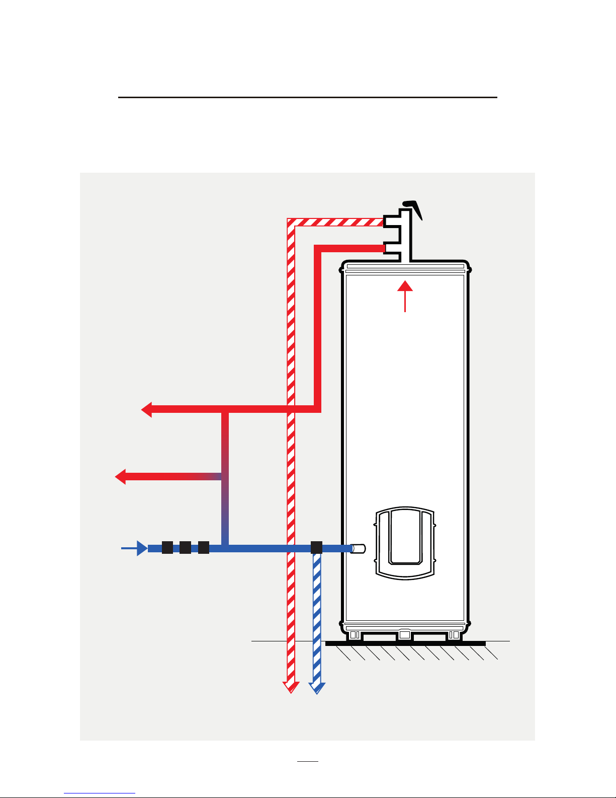
Hydraulic Connection
Cold water
PTR valve
(850 kPa)
Drain Lines
Untempered Hot water
(Kitchen, Laundry)
Tempered water 50°C
(Bathrooms)
1 2 3 4
1. Non-return and isolating valve
2. Line Strainer
3. Pressure Limiting valve
(350-500 kPa)
4. Expansion Control valve

5
Mandatory installation of a safety device in a frost free location (or
any other new device which limits the tank pressure) to 850 kPa
according to the nominal pressure, with a size of 3/4’’ on the input
of the water heater, respecting the local regulations .
Operate regularly the discharge of safety device to prevent scaling and
check that it is not blocked.
To drain the device switch o the power and the supply of cold water,
open the hot water faucets and manipulate the safety valve.
The pipes used must support 1 MPa (10 bar) and 100°C.
Cold Water Inlet
Cold water piping should be provided with a 350 – 500 kPa Pressure
Limiting Valve at the point of cold water connection to the
water heater. In addition to the Pressure Limiting Valve, it is a
requirement of AS 3500.4 & NZBC G12 that both a Stop Valve and a
Non Return Valve are installed upstream of the Product.
No parts (stop valve, pressure reducer, etc.) must be placed between the
pressure limiting valve and the cold water inlet of the water heater,
apart from a copper pipe.
Note: Since limited water discharge from Pressure Limiting Valve is
normal in the heating operation, the discharge pipe needs be
connected to external drain.
Hot Water Outlet
Where a maximum hot water delivery temperature is specied by local,
state or federal regulations, a tempering valve shall be installed at
the hot water outlet, as required.
The included specied Pressure & Temperature Relief valve must
be installed as shown in the schematic. The PTR valve should
be connected to a drain point to accommodate discharge as a
 Loading...