

Page 1
INSTALLATION INSTRUCTIONS
412 137
Family 4
No. 4061
Index C
Date 01/2011
VMC
Certification reference guide
NF205
www.marque-nf.com
Page 2

2
CONTENTS
1. WARNINGS ........................................................ 3
2. DESCRIPTION ..................................................... 3
2.1 General information ..................................... 3
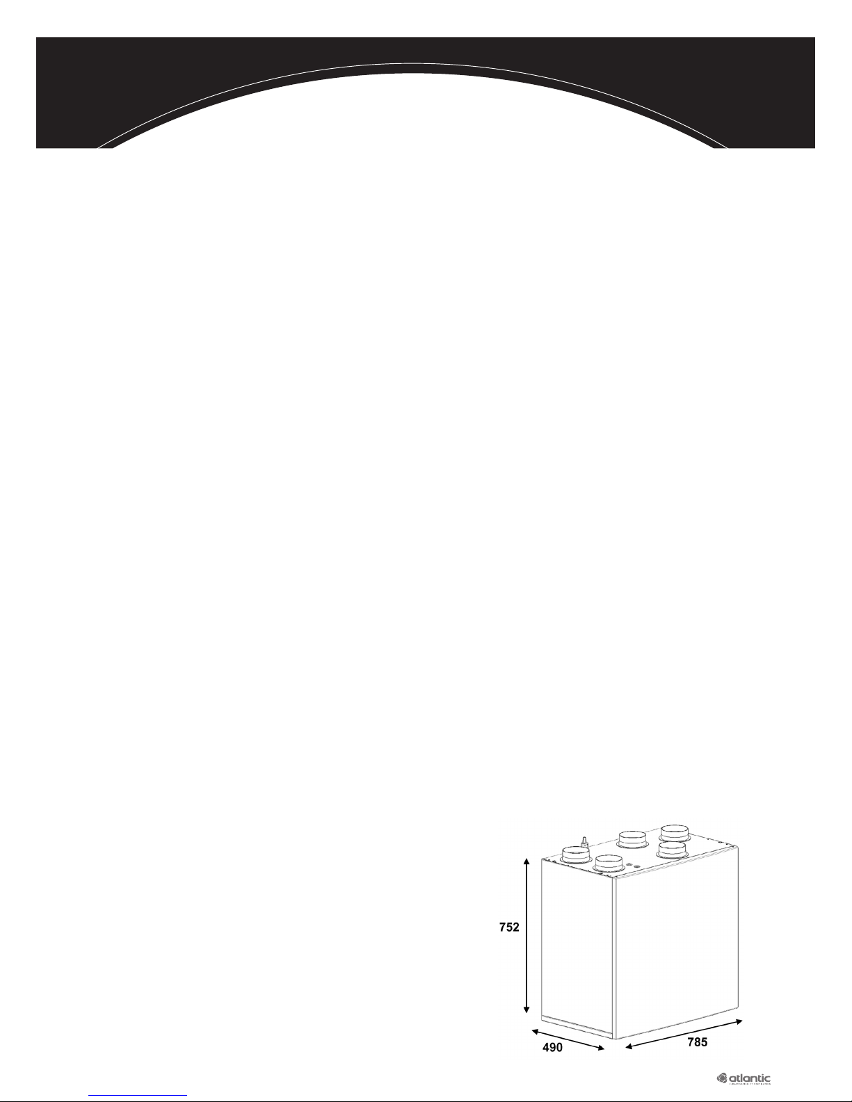
2.2. Dimensions/drawings .................................... 3
2.3. Construction/Dimensions .............................. 3
2.4. Technical specifications ................................. 4
3. PRODUCT INSTALLATION/ASSEMBLY .............. 4
3.1. Place of installation ....................................... 4
3.2. Assembly on concrete wall ............................ 4
3.3. Suspended assembly .................................... 4
3.4. Product fitted on the floor ............................ 4
3.5. Air pipe connections & associated terminals ... 4
3.6. Installation/accessory precautions .................. 5
3.7. Condensation connections ............................ 6
4. ELECTRICAL CONNECTION ............................... 6
4.1. Upstream connection .................................... 7
4.2. Electrical connection of the product .............. 7
5. PUTTING THE DUOLIX MAX INTO SERVICE ..... 7
5.1.
Inserting the batteries into the mobile contro
l ... 7
5.2. Linking procedure for your Duolix Max unit ... 8
5.3. Positioning the mobile control....................... 8
5.4. Configuring the product according
to the installation ....................................... 10
5.4.1. Choosing the language ..................... 10
5.4.2. Adjusting the flows .......................... 11
5.4.3. Adjusting the imbalance ................... 12
5.4.4. Adjusting the night cooling .............. 12
5.4.5. Choosing the night cooling
management mode .......................... 13
5.4.6. Adjusting the by-pass parameters ..... 13
5.4.7. Adjusting the filter’s service life ......... 14
5.4.8. Choosing the absence
management mode ......................... 15
5.4.9. Adjusting the absence flow ............... 15
5.4.10. Defining the connected accessories ... 16
5.4.11. Defining the thresholds for the
ground-coupled heat exchanger ..... 16
5.4.12. Finishing configuration ................... 17
6. APPENDIX ....................................................... 18
6.1. Managing an external night cooling device ... 18
6.1.1. Operational description ..................... 18
6.1.2.
Wiring an external night cooling device
... 18
6.2. Option to control night cooling using
a remote switch ......................................... 18
6.2.1. Remote control wiring for
night cooling .................................... 18
6.3. Managing a ground-connected
heat exchanger .......................................... 19
6.3.1. Operating description ...................... 19
6.3.2. Wiring an ground-connected
heat exchanger ............................... 20
6.4. Basic management of an auxiliary device .... 20
6.4.1. Operating description ....................... 20
6.4.2. Wiring an auxiliary device ................. 21
6.5. Managing the absence function
using a presence sensor ............................. 21
6.5.1. Operating description ...................... 21
6.5.2. Presence sensor wiring ...................... 21
6.6. Input-Output diagram for the circuit board .... 22
6.7. Maintenance of the Duolix MAX unit ......... 23
Page 3
3
1. WARNINGS
CAUTION:
This appliance is not designed for use by people (including children) of reduced physical, sensory
or metal capacity, or those inexperienced or ignorant unless they have received prior instruction or
supervision from someone responsible for their safety, about the use of the appliance
The central unit must be installed in the living area of the house and not in the roof spaces. The
networks of pipes must be installed, if possible, in the inhabitable space. If this is not the case, they
must be insulated with at least 50 mm of glass wool. Non-compliance with these conditions leads to
deterioration in the performance of the dual-flow central unit.
2. DESCRIPTION
2.1. General information
High-output dual-flow ventilation for houses.
Product controlled by a stylish and ergonomic radio remote control unit.
Thermal efficiency: 91.5% certified
Low-consumption motors.
Full by-pass for fresh air enabling optimum free cooling in summer.
Flow manifold on the waste air network resulting in reduced consumption all year round.
BOOST function: Increased flows for better night coolinge.
Option to manage a ground-coupled heat exchanger. Numerous possible configurations (see appendix).
Dual-flow ventilation enabling the fresh air to be blown into the «living» rooms (bedrooms, lounge,
living room) and waste air extracted from the damp rooms (kitchen, bathrooms, washrooms).
A network of ducts enables air to be distributed and blown into the house.
The external fresh air is filtered and pre-heated by passing through a highly-efficient heat exchanger.
This exchanger recovers the energy from the extracted air without mixing it with the renewed fresh air
2.3. Construction/Dimensions
RAL 7047 painted, galvanised steel sheet enclosure.
Internal parts made from grey PSE material.
RAL 9010 white, polymer fascia.
Product equipped with:
- a high-output plate heat exchanger (91.5% certified),
- two F7 filters on the fresh and waste air networks,
- a full by-pass for the fresh air
- a flow manifold between the kitchen and domestic
water network,
- two EC low-consumption motors
- a circuit board,
- a radio remote control unit
!
!
Page 4
4
2.4. Technical specifications
Max. flow 300 m3/h under 100 Pa.
Electrical specifications:
• Certified electrical power: 24.1 to 70.5 W-Th-C.
• Max. 200 W consumption for the two fans (maximum current = 1 A)
• In the case of optional output wiring: max. consumption of 100 W
(maximum additional current = 0.5 A)
3. INSTALLING/ASSEMBLING THE PRODUCT
3.1. Place of installation
Installation in a living area in a laundry room or cellar.
3.2. Assembly on concrete wall
Mount the strip on the wall ensuring it is horizontal.
Each mounting hole on the wall mount profile must have a wall plug so that the
permissible load can reach 120 kg.
Hook the product on to the strip.
3.3. Suspended assembly
Mount 4 vertical struts (threaded rod and M5 plug so
that that the permissible load may reach 120 kg) in the
designated places on the front of the product.
Hang the product on the ceiling using these 4 struts,
ensuring it is horizontal.
3.4. Product fitted to the ground
Use the 4 optional feet (feet part no.: 809 538) supplied
with the accessories.
Screw in the feet under the product using the 4 M8 screws supplied.
Place the product on the ground ensuring it is horizontal.
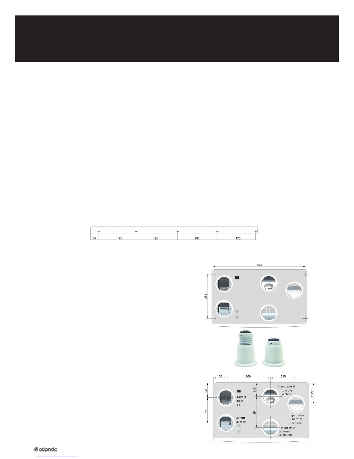
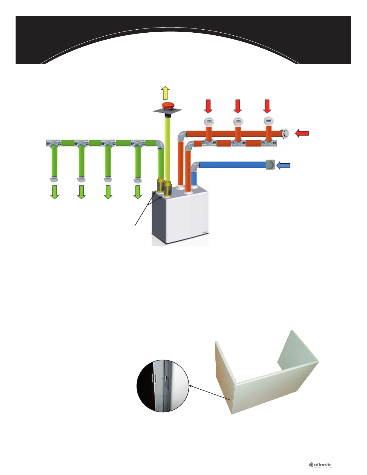
3.5. Air pipe connections & associated terminals
There are five tappings on the product - see the air pipe
connection diagram opposite.
It is preferable to install the network in the living spaces
Ensure that insulated pipes are used and comply with the
requirement for 50 mm rock wall
Page 5
5
Recommendations concerning putting into service:
Each main part should include an air vent so that the ventilation by sweeping principle can be
adhered to. Network balancing shall be taken care of by a sizing study
The coupling of the fan unit to a ground-connected heat exchanger requires a sizing study to
be performed beforehand.
3.6. Installation/accessory precautions
Mounting the duct cover:
• Allow 500 mm between the ceiling and the top of the device).
• The duct cover is in three sections.
• Attach each section to the other using the lugs designed for this purpose.
• Position the front panel on top of the Duolix MAX,
with the sides apart and then clip them onto
the designated hooks.
CAUTION:
Check that no rubble or other foreign bodies risk damaging the fans once they are switched on.
This product includes two fans.
Take the necessary precautions to ensure the correct installation of the product and its network in
order to avoid any noise disturbance
Option to install silencers at the product’s outlet (PAS 125 DF part no.: 422 535).
!
Roof cap CPR 125 part no.:
422 563 (red)
or 433 564 (slate)
Domestic water outlets
PB 80 A 30 PN part no. 422 492
or PB 80 A 15 PN part no.: 422 494
Blower outlets
PB 80 R part no. 422 248
Silencers
PAS 125 DF part no.: 422 535
Grid ME 125
part no.: 543 191
Kitchen outlet
GB 125 NP
part no. 422 152
Page 6
6
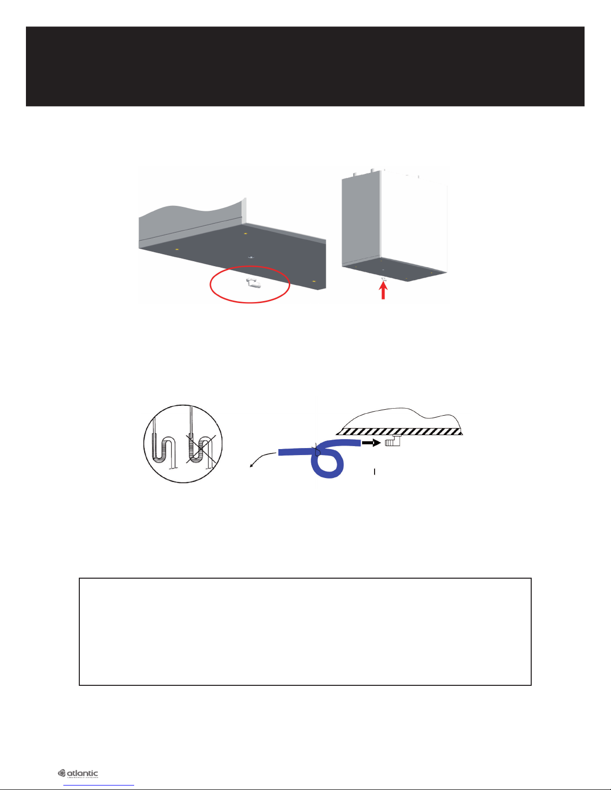
3.7. Condensation connections
Clip the condensation union under the product (supplied).
Connect the waste pipe (not supplied) to the drain.
Fill the siphon and immerse the waste pipe to prevent suction noises.
Use a transparent siphon, if possible, so that the water level can be checked.
The siphon should always be filled.
Example of drain connections:
4. ELECTRICAL CONNECTION
CAUTION:
BEFORE STARTING ANY OPERATION REQUIRING THE REMOVAL OF THE TERMINAL ACCESS PANEL,
DISCONNECT THE DEVICE FROM THE MAINS BY SWITCHING THE BI-POLAR CIRCUIT BREAKER AND
ENSURING THAT THE SUPPLY CANNOT BE RESTORED ACCIDENTALLY
THIS EQUIPMENT MUST BE INSTALLED BY PERSONS WITH THE APPROPRIATE QUALIFICATIONS.
THE INSTALLATION SHOULD COMPLY WITH STANDARD NF C15-100 AND GOOD PROFESSIONAL PRACTICE.
EACH PRODUCT OR COMPONENT INVOLVED IN INSTALLATION MUST ALSO BE COMPLIANT WITH THE
APPLICABLE STANDARDS.
If the supply cable or another conductor is damaged, it must be replaced by the manufacturer, its
after-sales service or persons with similar qualifications in order to avoid danger.
Drain pipe Ø 19 CO 16/20
part no.: 809 627
Condensation drainer to clip
under the product
To the drain
!
Page 7

7
4.1. Upstream connection
Protection of the device against upstream short-circuits with contacts opening a minimum of 3 mm,
2.5 A maximum rating bi-polar circuit breaker and circuit protected by 30 mA max. differential
circuit breaker.
4.2. Electrical connection of the product
To connect the product to the 230 VAC electrical supply, it does not need to be opened.
The Duolix MAX is a class I device and must be connected to earth.
Supply with a 1.5 mm² rigid, dual-insulation cable or 1.5 mm² wires under an annealed sleeve with a
maximum diameter of: 16 mm held in position by a tear protection compliant with standard NF C15100 and good practice.
The cable temperature resistance to be used for this connection should be at least 90°C.
Strip the conductors back 5 to 6 mm in order not to risk them coming into contact with other wires
The earth wire (green yellow) should be longer than the other conductors (approx. 5 to 10 mm).
The wires should not be tightened on the insulator.
The product is equipped with a 2P plug and earth.
- Open the plug
- Connect Phase, Earth and Neutral in the plug
- Close the plug
- Connect the plug to the product
5. SETTING UP THE MAX DUOLIX
CAUTION: To set up the unit, switch on the device
5.1. Inserting the batteries into the control
The unit should be electrically connected and supplied before switching on the control for the first time.
Insert three 1.5 V alkaline batteries (AAA LR03 type) in the direction indicated.
!
Single-phase supply
230 VAC + Earth
Neutral
Earth
Phase
Page 8
8
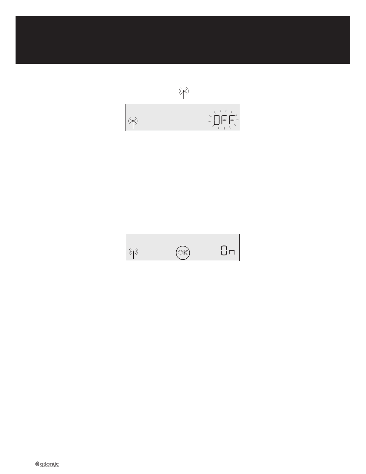
After inserting the batteries, press a key.
The flashing message «OFF» is displayed and the symbol appears on the screen.
The «OFF» message indicates that the control is not linked to the Duolix MAX unit. Linking them
enables the control and the Duolix MAX unit to recognise each other and to communicate with each
other (no interference possible with another unit in the vicinity).
CAUTION: There is a risk of explosion if the batteries are replaced with incorrect batteries. Dispose of
used batteries in accordance with the instructions.
5.2. Linking procedure with the Duolix Max unit
Move towards the dual-flow unit with the control.
• If a link between the control and unit is possible, the following message appears for seven to eight
seconds, then disappears.
The linking procedure has been successful.
• If this message does not appear, follow the linking procedure:
1. Switch off the electrical supply to the Duolix MAX unit directly from a switchboard via the
relevant circuit breaker.
2. Wait for at least 20 seconds
3. Re-establish the electrical supply to the Duolix MAX unit via the circuit breaker.
4. Go to within three metres of your Duolix MAX unit with the control.
• In certain exceptional cases (loss of link), carry out the first four stages stated above, then press the
«Mode» key for ten seconds to launch linking.
5.3. Positioning the control
The range of the control may vary depending on the obstacles (walls, floors, etc.). In most cases, the
range is sufficient to position the control at any location in the house.
Recommendations:
• The control must not be exposed to a source of dampness (shower, basin, etc.)
• The maximum recommended ambient temperature around the control should not exceed 40°C
continually.
• To guarantee correct operation, it is not advisable to place or mount the control on a metal support.
OK
!
!
Page 9

9
Reception quality
The reception quality of the control may be displayed by pressing the key for 5 seconds.
The reception level will appear for
a minute if no key is touched.
To solve this, move towards the Duolix MAX unit’s mobile control. If the problem persists, carry out the
linking procedure again. Refer to paragraph 5.2 «Linking procedure with the unit».
Fit on a flat surface
The control can be placed on any support surface.
For improved stability, fold out the rear support in
order to place the control in the «easel» position
Mounting on the wall
To place the control on a wall, the mounting
support on the rear needs to be detached first:
Then mount the support on the wall with the screw
(not supplied) and the plugs suitable for your wall.
1 - Separate the base from the support 2 - Pull to unclip it
3 - Use the mounting holes to
attach support to the wall.
4 - Place the control against
the support so that it can
be clipped in together.
If the following screen appears, this means
that the control is not receiving the signal.
Page 10

10
5.4. Configuring the product according to the installation
The Duolix MAX control has two navigation levels:
- a specific Duolix Max configuration menu
- a specific menu for the occupant of the house
To configure the Duolix Max it is necessary to go into the «installer» menu. To do this, press the «left
arrow» and «right arrow» at the same time for three seconds.
The following screen then appears:
Tip:
- Important: the first pages of the installer menu are the
most important as they requiring setting for the house
concerned. The next pages are optional and refer to
specific installations (presence of ground-connected
heat exchanger, etc.)
- During installation, the button enables you to go
back to the previous stage.
- During installation, the button enables you to
«skip» the next stages and go directly to the end of
the configuration menu.
5.4.1. Choosing the language
The relevant screen is the following:
Place the line under the desired language (FR for French
and UK for English) using the navigation keysand
then confirm with the central key
When the OK symbol appears, the choice of language
is confirmed.
FR UK
FR UK
Page 11

11
5.4.2. Adjusting the flows
Duolix has optimum flow management to limit energy consumption as much as possible while complying
with regulations in force. It adjusts the extraction flow and air flow with precision in accordance with the
order to activate the large kitchen flow or not.
To do this, it is necessary to provide the unit with two flow values. These two values are given in the table
below according to the configuration of the house:
Page 12

12
Provide the control with the «Val 1» value from the
previous table.
Use the navigation arrows and to increase or
reduce the desired flow value.
Then validate the desired value by pressing
When the symbol OK appears, the choice is confirmed.
Provide to the control with the value «Val 2» from the
previous table.
Use the navigation arrows and to increase or
reduce the desired flow value.
Then confirm the desired value by pressing
When the OK symbol appears, the choice is confirmed.
5.4.3. Adjusting the imbalance
Use the navigation arrows and to modify the imbalance:
• Pressing the left arrowreduces the air injection flow
(for an unchanged extracted air)
• Pressing the right arrowincreases the air injection
flow (for unchanged extracted air);
Then validate the desired value by pressing
When the Ok symbol appears, the choice is confirmed.
5.4.4. Adjusting the night cooling flow
Use the navigation keysandto increase or reduce
the desired flow value during night cooling activation.
Then validate the desired value by pressing
When the Ok symbol appears, the choice is confirmed.
m3/h
Val 1
Max
m3/h
BOOST
m3/h
Val 2
m3/h
Page 13

13
5.4.5. Choice of night cooling management mode
The Duolix MAX manages by default, automatically, night cooling in accordance with certain
temperature conditions. For example, during a summer’s night, the system will increase the ventilation
flow (to the value set in the previous chapter) when the temperature conditions are satisfactory to
benefit from efficient night cooling.
If, in some cases, the occupier does not want the device to control night cooling, the parameter needs
to be modified.
N.B.
In all cases, this choice does not deactivate the option of manual night cooling if required by
the occupant.
When the following page appears, choose:
• «Auto» so that the Duolix MAX manages night cooling automatically.
• «No», for no automatic night cooling.
Use the navigation keys to switch from «No» to «Auto» andvice-versa.
Then confirm the choice by pressing
When the OK symbol appears, the choice is confirmed.
5.4.6. Adjusting the by-pass parameters
The default values are those recommended by Atlantic.
It is possible to adjust the upper and lower temperature thresholds for activating the by-pass.
Operating principles:
BOOST BOOST
Page 14

14
Upper threshold value: (recommended as 24°C)
Use the navigation arrowsandto increase or
reduce the upper temperature threshold.
Then confirm the desired value by pressing
When the Ok symbol appears, the choice is confirmed.
Lower threshold value: (recommended as 12°C)
Use the navigation keysandto increase or reduce
the lower threshold value.
Then confirm the desired value by pressing
When the OK symbol appears, the choice is confirmed.
5.4.7. Adjusting the filter’s service life
Use the navigation keys and to increase or reduce
the filter’s service life before the alarm (can be adjusted
from 8 to 24 months with a factory setting of 12 months).
Then confirm the desired value by pressing
When the OK symbol appears the choice is confirmed.
Max
°C
Min
°C
Filtre
Mois
Page 15

15
5.4.8. Choosing the absence management mode
The Duolix MAX enables you to reduce the flows when the occupant is not at home.
There are two management modes:
• Default, with no additional options, the occupant may, before his departure, activate absence mode
and program the time he will be absent. The unit then reduces its flowrate in accordance with the
programmed value during the time set by the occupant, but if the occupant returns before the set
period of time, he can cancel the absence mode.
• If the presence sensor option (part no.: DIP code 323 020 exposed or 323 021 enclosed) was chosen
and installed, the occupant may choose to activate the «auto» absence mode before he leaves. The
unit then reduces its flowrate in accordance with the programmed value until it detects the return of
the occupant. (see wiring details in the appendix).
Use the navigation keysandto switch from «Man» to «Auto» and vice-versa.
If the sensor option has been chosen and installed: select «Auto»
If the option has not been chosen: choose «Man».
Then confirm the desired value by pressing
When the OK symbol appears, the choice is confirmed.
5.4.9. Adjusting the absence flow
The flowrate needs to be adjusted when the absence
function is activated.
Use the navigation arrowsandto increase or reduce
the desired flowrate when activating absence mode.
Then confirm the desired value by pressing
When the Ok symbol appears, the choice is confirmed.
Number of main parts
2 / 3 / 4 5 6 7
Maximum total flowrate (m3/h) 90 105 120 135
Minimum flowrate in kitchen (m3/h)
45 45 45 45
Absence
Absence
Absence
m3/h
Page 16

16
5.4.10. Defining the connected accessories
The Duolix MAX offers the option to be able to manage accessories like a ground-connected heat
exchanger or other systems.
In the case of a ground-connected heat exchanger, the Duolix MAX manages the valve choosing the
source of fresh air (ground-connected heat exchanger or not).
Refer to the appendix for information on the electrical connection of these auxiliaries.
Use the navigation keysandto select:
• That there are no connected accessories.
• The presence of a ground-connected heat exchanger
• The presence of an auxiliary
If ground-connected heat exchangers have been chosen, refer to the following paragraph.
If another choice was made, refer to paragraph 5.4.12 «End of configuration»
5.4.11. Defining the thresholds for the ground-connected heat exchangers
The Duolix MAX can control a ground-connected heat exchanger valve.
The principle is to supply the Duolix MAX central unit via the ground-connected heat exchanger air
inlet when the external air is below the minimum threshold (5°C for example) or above the max.
threshold (25°C for example) in order to heat the fresh air in winter and cool it in summer.
In the temperature range between these thresholds, the duct is negligible; it is therefore preferable to
pass through the fresh air inlet directly.
The Duolix MAX therefore controls this valve managing the fresh air source to be used in the house.
Lower threshold value: (recommended as 5°C)
Use the navigation keysandto increase or reduce
the value of the lower threshold.
Then confirm the desired value by pressing
When the Ok symbol appears, the choice is confirmed.
Aux
Aux
Aux
Min
°C
Page 17

17
Upper threshold value: (recommended as 25°C)
Use the navigation keys to increase or reduce the value
of the upper threshold.
Then confirm the desired value by pressing
When the Ok symbol appears, the choice is confirmed.
5.4.12. End of configuration
Use the navigation keysand to validate the end of configuration «End» or initialisation «Init»
enabling the factory settings to be returned to.
• If «End» is selected and confirmed by pressing : configuration is complete.
• If «Init» is selected and confirmed by pressing : the following screen is displayed.
Use the navigation keys and to switch from «yes» to «no».
• «Yes» reinitialises the parameters to their factory settings
• «No», finalises the configuration and saves the previously defined values.
Then confirm the desired value by pressing
When the OK symbol appears the choice is confirmed.
Max
°C
Reset
Reset
Page 18

18
6. APPENDICES
6.1. Managing an external night cooling device
6.1.1. Operating description
The Duolix MAX offers the option of controlling a device that assists with night cooling.
This consists of either:
• an external fan on a dedicated network
• and/or one or more valves on the existing ventilation network to assist with air injection and the
extraction at a particular location in the house.
(Refer to the diagram for the various examples -contact Atlantic)
6.1.2. External night cooling wiring kit
Connector kit part no: 412093
Example of adapted valve: RM 125
Example of fan: VCM EASY (part no.: 123 164)
VCM 160 AXP (part no.: 123 084)
VCM 200 AXR (part no.: 533 020).
Max. power of the external night cooling device: 100 W with a min. 0.9 phi cos
Connect the component (phase and neutral 230 VAC)
with the connection kit to the OUT4 terminals.
6.2. Option to control the night cooling via a remote switch
The Duolix MAX provides the option of controlling the night cooling (either internally or externally) by
the mobile control, of course, but also a wired remote switch (usually in the bathroom).
6.2.1. Night cooling remote control wiring
Connector kit part no: 412 093
Connect a switch to the connector kit on the
«IN1A» and «IN1B» terminals as the following
diagram illustrates:
The device’s wiring activates when
night cooling is activated.
100 W max.
Duolix MAX
circuit board
Remote switch actuating
the night cooling
Duolix MAX
circuit board
Page 19

19
6.3. Managing ground-connected heat exchanger
6.3.1. Operational description
The Duolix MAX can control a ground-connected heat exchanger valve.
The principle is to supply the Duolix MAX central unit via the ground-connected heat exchanger fresh
air inlet when the external air is below the minimum threshold (5°C for example) or above the max.
threshold (25°C for example) in order heat the fresh air in winter and cool it in summer.
Within the temperature range between these thresholds, the duct is negligible, it is therefore
preferable to pass through the fresh air inlet directly.
The Duolix MAX controls this valve by managing the source of fresh air used in the house.
N.B.:
These min. and max. thresholds can be adjusted in accordance with the installation. (See chapter 5.4.10)
6.3.2. Ground-connected heat exchanger wiring
Connector kit part no: 412,093
Ground-connected heat exchanger kit (All or Nothing valve RR125-M1 part no. 523 845; 1 kohm ext.
sensor part no.: 412 094)
The valve should be placed on the fascia air inlet and in the normally closed position (see diagram above).
If the external temperature is below 5°C or greater than 25°C (default) the air will pass through the
ground-connected heat exchanger and OUT5 will activate.
5
4
2%
A
ir neuf
Page 20

20
CAUTION: It is very important to position the selector in the valve motor’s direction of rotation in
the correct position so that the valve is open between 5 and 25°C (passage of the air mainly through
the fascia).
The cables used must be dual-insulation conductors (stripped back 5 to 8 mm), with a cross-section of
0.75 mm², at least H 05 W-F type and compliant with the current standards.
The external temperature sensor must be positioned in the shade (north-facing wall) and at a height of
at least 1 m 50 from the ground.
Adhere to the following connection diagram:
6.4. Basic management of an auxiliary
6.4.1. Description of the operation
The Duolix MAX enables an auxiliary to be controlled via its mobile control. This auxiliary may be an air
valve for example.
(See the diagram for the various examples - contact us)
Relevant example:
• Limit the use of the anti-frost function to improve the efficiency of the Duolix MAX in cold or very
cold regions: valve on the fresh air network enabling a source of temperate air to be mixed with
the fresh air, in a non-living area (garage, cellar, etc.)
• Recovers the energy from the crawl space for the summer: valve activating additional extraction at
VS level or not.
• …..
!
Duolix MAX
circuit board
Valve motor
External sensor
230 VAC
protected to 2 A
Page 21

21
6.4.2. Auxiliary wiring
Max. output of the auxiliary: 1500 W
CAUTION: The output is a «dry contact» type to supply an external component via an external
power supply. (see diagram below)
Provide a dedicated circuit breaker for this supply.
6.5. Managing the absence function using a presence sensor
6.5.1. Description of the operation
If the presence sensor option (part no.: DIP code 323 020 exposed or 323 021 enclosed was chosen
and installed, the occupant may choose to activate the «auto» absence mode before leaving. The unit
reduces its flowrate in accordance with the programmed value until the unit detects the return of the
occupant to their house.
6.5.2. Presence sensor wiring
Duolix MAX
circuit board
!
Separate power supply from
the Duolix Max unit protected
in accordance with the
specifications of the auxiliary
Duolix MAX
circuit board
Auxiliary
Page 22

22
6.6 Circuit board input-output diagram
Page 23

23
6.7. Maintenance of the Duolix MAX unit
6.7.1. Duolix MAX unit upkeep
Upkeep of your Duolix MAX starts with changing your filters regularly.
CAUTION: The upkeep of your Duolix MAX (changing the filters) never requires the large protective
cover with the flash sticker to be removed
Regularly (at least every 13 months), if you do not have a annual service contract, contact your installer
for more in-depth cleaning of your Duolix MAX (cleaning the exchanger, the condensation basin, etc.)
This type of maintenance should be performed by a qualified person.
6.7.2. Maintenance of the Duolix MAX unit by qualified personnel.
CAUTION: Switch off the electrical supply to the device without fail before opening the protective
metal cover.
Remove the white, polymer fascia.
Unscrew the seven metal fascia screws.
Remove the exchanger by pulling it towards yourself.
Place the exchanger in slightly soapy warm water.
Rinse well.
Leave it to drip dry for a few moments.
During this time, check and clean the condensation basin (check that the drain is not obstructed).
Check the cleanliness of the fan turbines;
Replace the exchanger ensuring that it is correctly positioned in its runners
Refit the metal fascia
Screw it on.
Refit the white polymer fascia.
Page 24

Atlantic Climatisation et Ventilation - S.A.S. au capital de 2 916 400 euros - RCS Lyon B 421 370 289
www.atlantic-pros.fr
Installer’s stamp:
Australia
4/13-25 Church Street
Hawthorn, Victoria
Free Call: 1800 677 857
Web: www.atlantics.com.au
Email: sales@atlantics.com.au
New Zealand
PH: 0800 422 000
Web: www.atlantics.co.nz
Email: sales@atlantics.co.nz
Head office:
Atlantic Climatisation et Ventilation
13, Bd Monge - ZI - BP 71 - 69882 Meyzieu Cedex
Tél. 04 72 45 11 00 - Fax 04 72 45 11 11
www.atlantic-pros.fr
 Loading...