

Atlantic ATL F10E2-1.28 CRVBB, ATL F10E2-1.28 PRVBB, ATL F10E2-1.33 PRVFFBB Installation Instructions Manual
Page 1
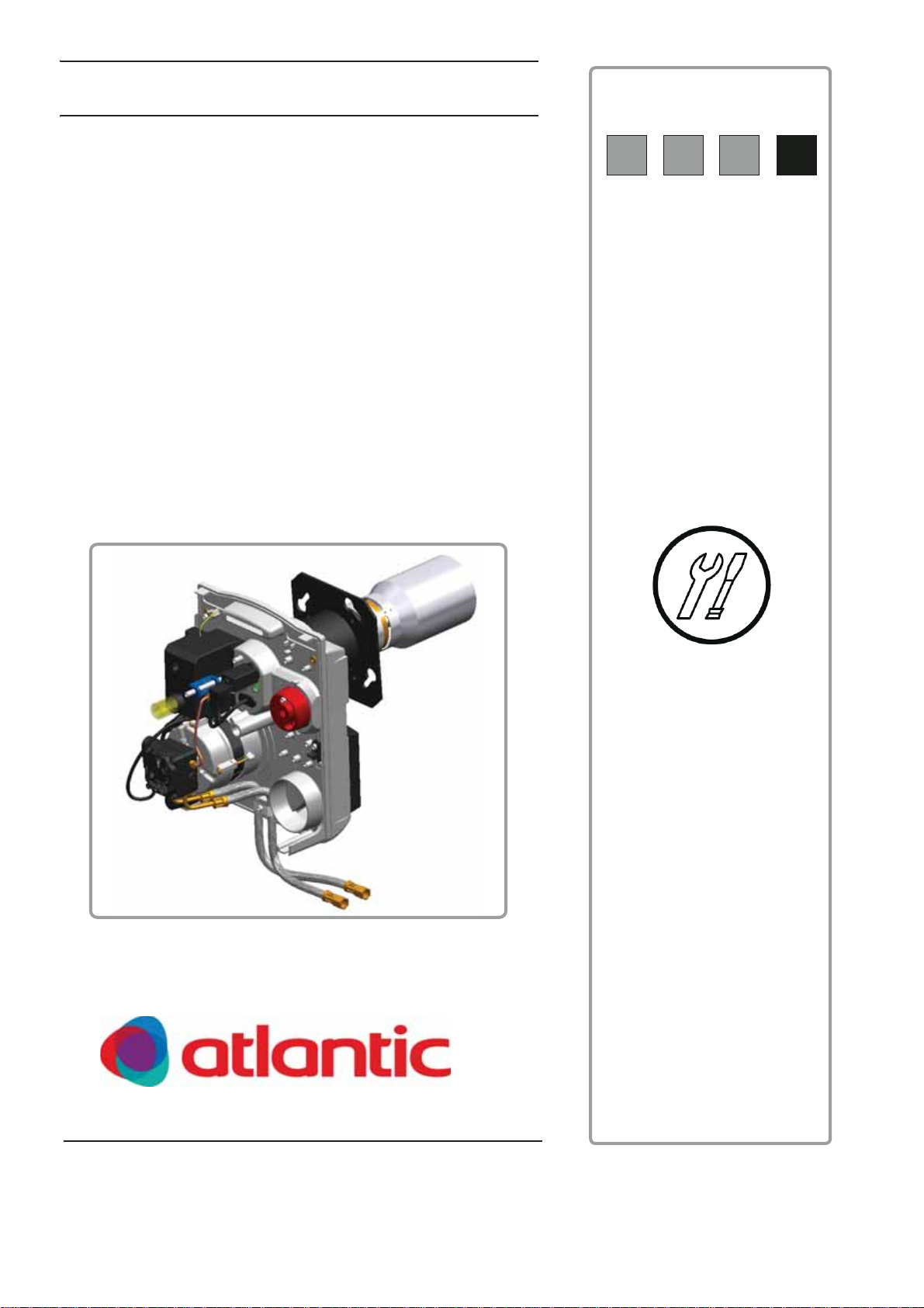
Fuel oil burner
FR
NL
EN
DE
ATL F10E2-1.28 CRVBB - Type 075509
ATL F10E2-1.28 PRVBB - Type 105579
ATL F10E2-1.33 PRVFFBB - Type 105581
(for alféa hybrid duo)
Document : 1552- 4- 02/2013
01081
Installation instructions
Intended for the qualified professional
To be kept by the user for consultation at a
later date
www.atlantic.fr
www.atlanticbelgium.be
400000612 - D
Page 2

Declaration of conformity CE
Declaration of compliance D.R. 17/07/2009 - BE
Manufacturer SPM SAS
2, avenue Josué Heilmann
Z.I. de Vieux-Thann
F - 68800 Vieux-Thann
+33 3 89 83 63 00
;
+33 3 89 83 63 07
Issued by See end of notice
We hereby certify that the range of equipment specified below is in accordance with the format stated in the
EC declaration of comformity, that it is manufactured and distributed in accordance with the regulations and
requirements in european directives and with the regulations and requirements defined in the Royal Decree
dated 17/07/2009.
Product type Fuel oil burner
Models ATL F10E2-1
Applied standards Royal Decree dated 17/07/2009
BImSchV 2010
Fire protection VKF
Air protection LRV 92
Standard EN 267
2004/108/EC Electromagnetic Compatibility Directive
Reference Standards: EN 55.014 - EN 61000
2006/95/EC Low Voltage Directive
Reference Standard: EN 60.335
Inspecting organisation GWI - 15705 - 12/02/2007
Measured values
NOx < 81 mg/kWh ; CO < 27 mg/kWh
Date : 02/2013 Signature
Chairman
M. Philippe Weitz
Installation instructions "1552 - EN"
Page 3

Contents
Security Measures..................................................................................................................................................4
Important information ............................................................................................................................................4
Burner description..................................................................................................................................................5
1 Brief description ..................................................................................................................................................................5
2 Dimensions .........................................................................................................................................................................5
3 Technical data.....................................................................................................................................................................6
4 Main parts ...........................................................................................................................................................................7
Command and safety box BB-LEV-P..................................................................................................................10
Installation.............................................................................................................................................................11
1 Maintenance...................................................................................................................................................................... 13
2 Checking the flame detection cell (IRD 1010)...................................................................................................................13
3 Nozzle selection................................................................................................................................................................14
4 Fuel oil nozzle assembly ................................................................................................................................................... 14
5 Check the position of the combustion head and the ignition electrodes ...........................................................................14
6 Positioning the mechanism ...............................................................................................................................................15
7 Fuel and electrical connections.........................................................................................................................................15
Adjustment............................................................................................................................................................16
1 Recommended Settings....................................................................................................................................................16
2 Setting the burner.............................................................................................................................................................. 17
Checking and maintenance.................................................................................................................................18
Electrical diagram.................................................................................................................................................19
Operating incidents..............................................................................................................................................20
Spare parts - ATL F10E2-1...................................................................................................................................21
Installation instructions "1552 - EN"
Page 4

Security Measures
• Installation must be carried out in accordance with current laws.
• Current safety and accident prevention regulations must be respected at all times.
• Burner assembly, start up, operation and maintenance (inspection, servicing, repair) must be carried out by qualified, properly
trained personnel.
• Only the manufacturer is authorised to undertake repair work on the electrotechnical parts, flame detection devices and other
safety equipment.
• Changes and modifications not specified in this document and which may cause serious malfunction to the burner are
prohibited..
• All work, except for adjusting the burner, shall only be carried out after the burner has stopped and after the power
supply has been disconnected.
• We shall not accept any responsibility for any damage and disturbance arising from not following these instructions !
The flame tube temperature is high. The baffle temperature is high. Handle with care.
Important information
Handing over the system to the user
• When the system is being handed over to the user, the installation engineer shall draw particular attention to the actions that
the user is authorised to carry out (when the burner is on safety for commissioning the system) and to the actions and
modifications that may only be undertaken by qualified personnel. Please refer to "User Instructions" supplied with this
document.
• The user must ensure that only a qualified professional has maintained the burner.
• This document is an integral part of the burner. Please keep it carefully in the furnace room near to the appliance.
Installation maintenance
To get the most out of your burner and to avoid operating difficulties, make a a qualified technician carries out the following :
• Cleaning the combustion head.
• Replacing the fuel oil nozzle.
• Replacing the electrodes (if required).
• Checking the burner's operation.
• Checking and cleaning the boiler.
• Checking and cleaning the chimney.
• Checking and cleaning the new air heater input.
For wearing parts, see the list of spare parts at the end of these instructions.
Used symbols
Caution danger !
Risk of injury and damage to equipment.
Attention must be paid to the warnings on safety of persons and equipment.
Specific information. Information must be kept in mind to maintain comfort.
, ,
1, 2, 3
Assembly stage.
Markers.
4
Installation instructions "1552 - EN"
Page 5
Burner description
1 Brief description
ATL F10E2-1 range burners are compact fuel burners which meet standards on burners with air flow adjustment:
• They are delivered with cables connected.
• They are fitted to the boiler using a welded flange
• All of the parts are assembled on an easily accessible plate.
• The plate containing the parts is located for optimal maintenance.
• Flame surveillance is carried out by an infra red cell.
• Ignition is by electronic transformer.
• The nozzle line is reheated.
Envisaged use
ATL F10E2-1 range burners are designed to specifically operate with "hot water furnaces" for heating premises and domestic hot
water.
• Fuel: standard fuel oil and low-sulphur fuel oil (max. viscosity: 6 mm²/s at 20°C).
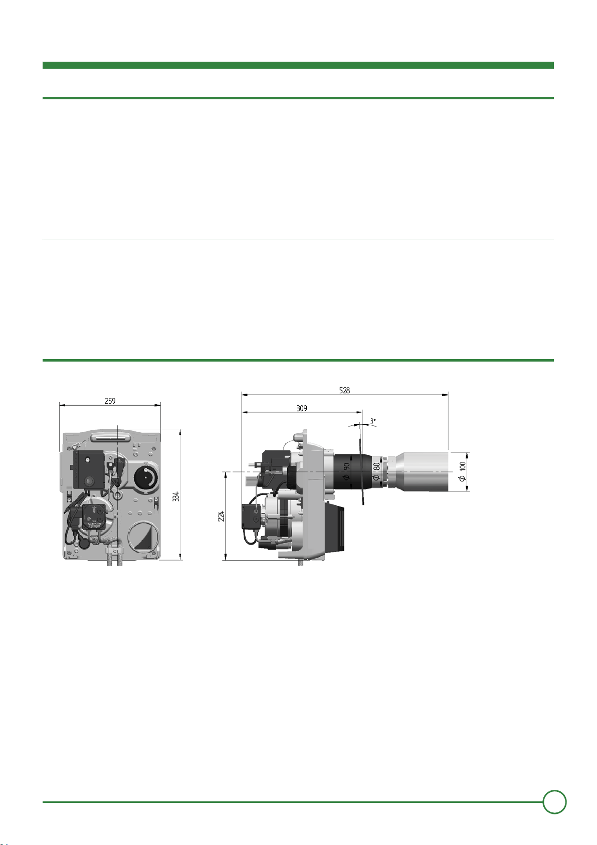
2 Dimensions
Dimensions (in mm)
01083
Possible drill holes in the fire box door
Leave a minimum space of 0.80 m behind the burner, free of any obstacles to allow for maintenance.
Installation instructions "1552 - EN"
5
Page 6
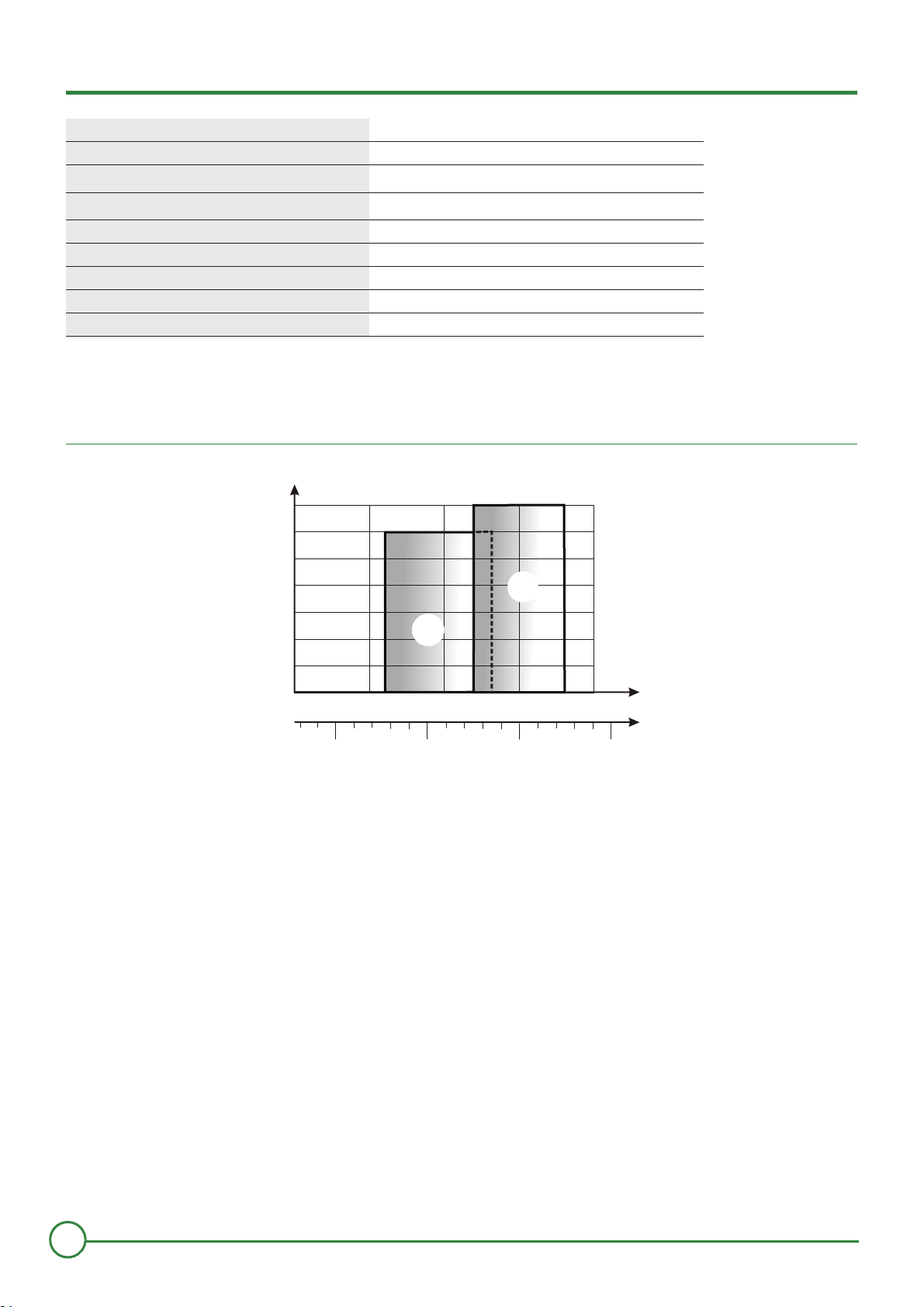
3 Technical data
1.5
01084
1.0
0.8
0.6
0.4
0.2
0
15
20
25
30
35
1.2
1.4
2.0
2.5
21
28
3.0
27
1
2
Burners ATL F10E2-1.28 ATL F10E2-1.33
Operation 1 stage 1 stage
Nominal output (kW)
Fuel flow (Kg/h)
Power consumption (W) 210 210
Nominal power of the motor (W) 90 90
Sound level at 1 m (dBA) 63 63
Net weight (kg) 12 12
Gross weight (kg) 14 14
(1)
Power at an altitude of 400 m and at a temperature of 20°C. Calorific power of fuel oil: LHV = 11.86 kWh/kg.
(2)
Fuel: domestic fuel (max viscosity 6 mm²/s to 20°C).
(1)
(2)
Power curves according to the EN 267 standard
(mbar) Fire box counter pressure
21 28 27 33
1.8 2.4 2.3 2.8
ATL F10E2-1.28 CRVBB
ATL F10E2-1.28 PRVBB
kW
Kg/h
ATL F10E2-1.33 PRVFFBB
6
Installation instructions "1552 - EN"
Page 7
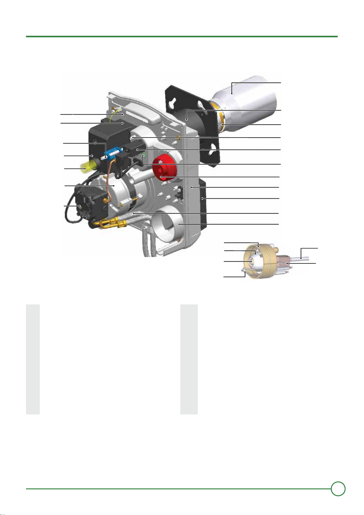
4 Main parts
01085
1
2
3
4
5
6
7
8
9
10
11
12
13
14
15
16
17
19
21
22
23
20
24
18
1 Fuel pump 13 Flame display record
2 Motor 14 Air valve adjustment button
3 Reset button 15 Housing
4 Wiring base frame and control and safety control box 16 Air enclosure
5 Recirculation slot adjustment screw 17 Fuel supply pipes
6 Ignition transformer 18 Air inlet
7 Part plate 19 Ignition electrode
8 Flame tube 20 Filler
9 Intermediate tube 21 air nozzle
10 Recirculation slot 22 Combustion head
11 Head air pressure measurement point 23 Filling line
12 Flame detection cell (Infrared cell) 24 Pre-heater
Installation instructions "1552 - EN"
7
Page 8
Fuel pump
It is a self aspirating geared pump which turns to the right(seen from above):
- Includes input filter and fuel pressure regulator.
- It is adjusted using a dual tube system but this may be changed to a single tube system.
The single tube system is illegal in some countries. Please check existing legislation.
Carefuly empty the fuel pump during start up.
1 Solenoid valve
2 Manometer measurement socket (Pressure)
3 Nozzle output
4 Fuel return (Dual tube/single tube conversion)
5 Fuel aspiration
6 Fuel filter
7 Vacuum gauge measurement socket (Depression)
8 Pressure pump setting screw : from 9 bars to 15 bars
Technical characteristics
Fuel pump SUNTEC AS 47
Ambient temperature (under the cover) 50°C
Manufacturer's pressure margin 7 - 15 bar
Max depression 0.35 bar
Max permitted pressure on entry 2 bar
Max permitted pressure on blocking 2 bar
Max pump air flow at 10 bar 45 l/h
Combustion head
Burner Combustion head
ATL F10E2-1.28 MB824
ATL F10E2-1.33 MB 827/22
8
Installation instructions "1552 - EN"
00992
Page 9

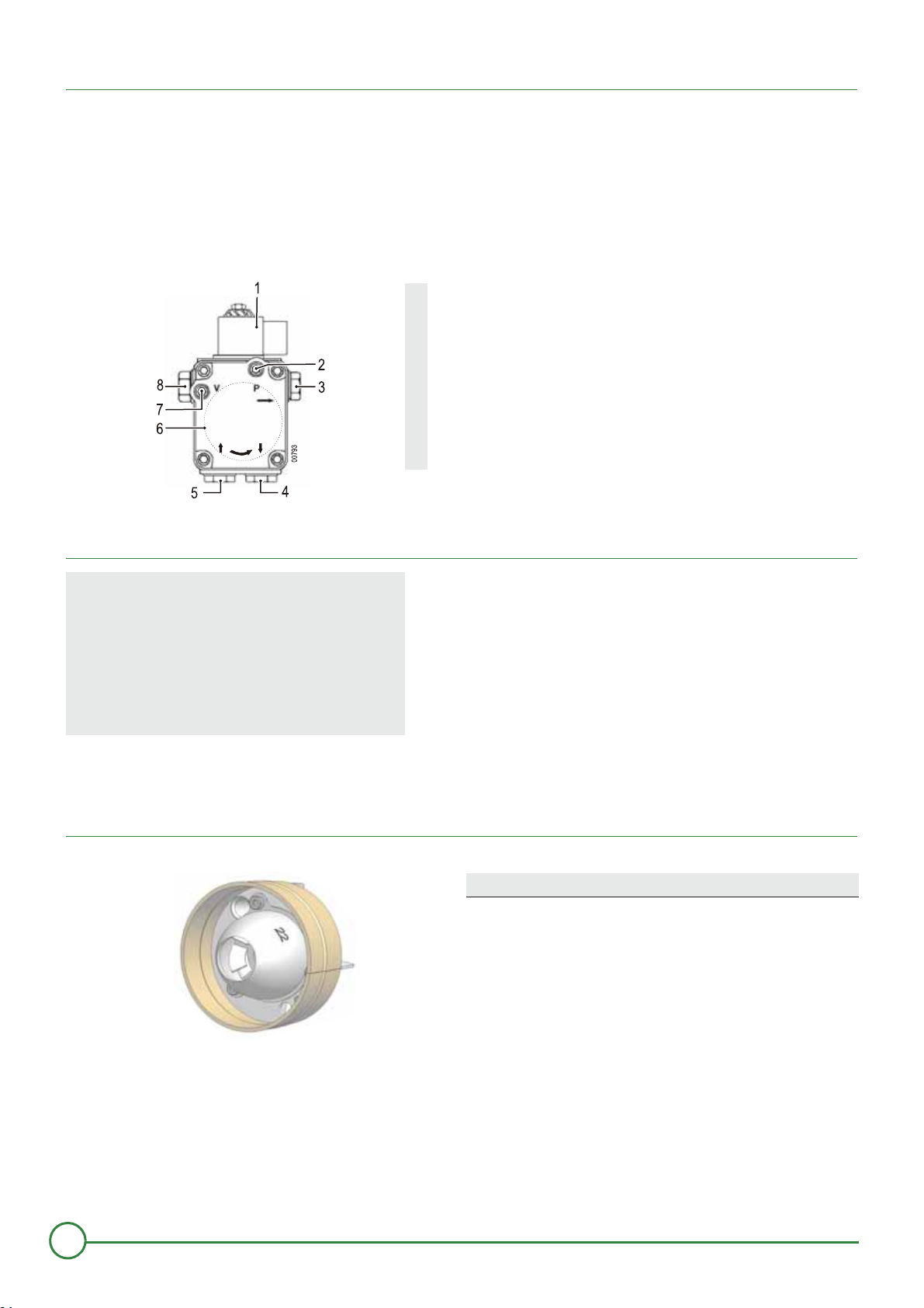
Base with cables for Command and safety box BB-LEV-P
00302
1
2
3
4
5
6
7
8
9
1 Fuel heater connection
2 Flame detection cell connection
3 Reset button
4 Motor connection
5 Electro-valve connection
7 pole connector
6
Burner to furnace connector
Green LED
7
Ignited Burner on
Off
Burner off
8 Transformer connection
9 Earth connection to the parts plate
9
Installation instructions "1552 - EN"
Page 10

Command and safety box BB-LEV-P
Operating cycle
F Flame detection
Z Ignition
M Burner motor
FT Unblocking the fuel heater
V Solenoid valve
OV Fuel pre-heater
SA External breakdown indicator
ta Fuel heater reheating time : 55 70 seconds (400 s max)
tv Pre-ignition and preventilation time: 15 seconds
tf Surveillance time for flare: 5 seconds
ts Safety time: 5 seconds
tn Post-ignition time: 7 seconds
tb Post-ventilation time = 30 s
If there is no voltage between L1 and T1 and the green LED on the command and safety box is off even though a thermostatic
request is pending, replace the command and safety box
The command and safety box is a safety device which must only be stacked on the base or removed when the
current has been switched off by the main heating installation switch.
The command and safety box is a safety device which must not be opened.
Information on the operation of the command and safety box (BB-LEV-P)
• If the burner is safe (Steady red light) : Press the reset button on the command and safety box for 1 second(s) to restart the
burner.
• Pressing the button for 3 s will shut down the burner.
10
Installation instructions "1552 - EN"
Page 11

Installation
00851
!!!
Recommendations for the recirculation slot
If the door is to be insulated, keep the recirculation slot free of all insulation material
Recommendations on electricity connection
A manually controlled sectioning device must be used to insulate the installation during main tenance, cleaning and
repair work. At the same time all non earthed conductors must be cut. This switch is not supplied.
The burner is manufactured to operate in a 230V - 50Hz single phase system.
Prior to any action on the burner, it has to be disconnected from the electricity supply.
Installation and electrical connections are to be made in accordance with existing regulations. Check that the earth
is properly connected !
The connection cables supplied are certified under DIN 4791.
Recommendations for fuel connection
The burner is supplied with dual tube fuel connection: an aspiration pipe and another for the return to the tank. A filter (mesh less
than 80 μm) must be located on the fuel oil aspiration to prevent the nozzle from becoming blocked.
For burners set for a power lower than 25 kW use a fuel filter with a mesh size of 40 μm
It is possible to connect a single tube from the filter: It is not advisable to use a single tube connection between the filter and the
burner's pump.
The fuel oil supply line will be constructed in compliance with prevailing standards in order to minimise drops in intake pressure
(elbows / dimensions...).
When commissioning the oil supply
- Check the entire oil installation for leaks,
- Disgas the oil supply (from the tank to the oil filter).
We strongly recommend the use of an air deaerator filter.
11
Installation instructions "1552 - EN"
Page 12

Single tube system with air separator for Low NOx burners
00189
u
v
w
x
z
y
Single tube system :
- 1 Pipe between the tank and the air separator
- 2 Pipes between the air separator and the burner.
1 Air separator
2 Single tube system
3 Fuel filter
4 Oil flow
5 Burner
6 Tank
Strong points :
- If there are slight leaks on the single tube pipe, the quantity of air in the oil is reduced.
- Eliminates the air contained in the fuel upstream of the pump. This optimises pump operation and reduces oil flow when the burner
is off.
- Optimises the oil pulverisation nozzle.
- Reduces oil filter fouling.
- The oil quality is more stable (No oil return to the tank).
- Enables the use of smaller pipe sections (Intake only of the quantity of oil required).
The use of the single tube system at low output is currently quite commonplace (See trade press regarding the single tube
system).
The use of a fibre-based filter must be avoided at all costs.
12
Installation instructions "1552 - EN"
Page 13

1 Maintenance
c
01143
1
!!
2
01144
b
a
c
4
3
Unplug the electricity connector.
Unscrew the 4 quick tightening screws.
Loosen the 2 bolts by a maximum of 2 turns.
Move the right hand bolt down and the left hand bolt up.
Extract the parts plate from the housing.
!
Position the parts plate on the housing screws.
"
Avoid any mechanical force on the turbine. Do not use the turbine as a support point in order to stop it from turning.
1
2
5
2
6
c
4
2 Checking the flame detection cell (IRD 1010)
Align the flame detection cell with the combustion head mirror .
Untighten screw .
Turn the combustion head to align the flame detection cell 1 and the mirror 2.
Tighten screw .
13
Installation instructions "1552 - EN"
Page 14

3 Nozzle selection
01145
3
4 mm
16 mm
29 mm
4
Check setting table on page 16 for nozzle selection.
4 Fuel oil nozzle assembly
A
a
01003
d
Disconnect the ignition electrode cables.
Untighten screw 1. Remove the turbulator.
Check the capacity of the nozzle in terms of the required furnace power and its performance. Replace it if necessary.
Tighten the nozzle.
5 Check the position of the combustion head and the ignition electrodes
Check the sides indicated below.
Adjusting the mark 3 using one or more 4 1 mm thick rings.
Be careful not to mask the flame detector to avoid any problems with flame checking.
Place the ignition cable around the nozzle line. Connect the ignition electrode cables.
Placing the electrodes in this position optimises burner start-up.
14
Installation instructions "1552 - EN"
Page 15

6 Positioning the mechanism
0
508
5
c
b
P
V
P
-
+
1
2
1
2
3
4
5
6
7
3
4
Carefully place the fuel oil line into the flame tube.
Attach the parts plate onto the housing.
Attach and fix the 2 bolts.
Tighten the 2 screws .
Tighten the 4 quick tightening screws.
!
7 Fuel and electrical connections
5
a
5
4
3
Attach the fuel oil flexible pipes onto their fixing flange.
Connect the burner pipes to the fuel installation.
Position and clip on the electric cable onto the parts plate (as shown in the diagram).
Plug in the electricity connection.
Fuel filter.
1
For safety reasons, do not connect the fuel until start up.
15
Installation instructions "1552 - EN"
Page 16

Adjustment
Recommendations for measuring combustion
Fine tune the burner so that it meets the existing local regulations.
It is important that the flow of combustion products between the chimney and the furnace nozzle is sealed in order to avoid
measurement errors.
In order to measure combustion: Keep to the burner's operating times:
• 10 min operation (Boiler at temperature).
• 20 min operation (Cold boiler).
After assembling and setting the burner:
• Check the soot index.
• Check the smoke gas emission values.
Keep to the advised settings to avoid having flame surveillance problems at low powers
Recommendations for adjusting the recirculation slot
The recirculation gas proportion is based on the recirculation slot. This gas proportion directly affects the NOx rate.
The larger the recirculation slot, the lower the NOx rate. However, flame stability decreases. The recirculation slot
must be set to obtain the lowest possible NOx rate with good flame stability.
1 Recommended Settings
Burner
Burner
ATL F10E2-1.28
ATL F10E2-1.33
(1)
Ring from 1 mm
In grey: factory setting
power
(kW)
23
25
28
28
30
0.55 - 80°S
0.55 - 80°S
0.55 - 80°S
0.55 - 80°S
0.65 - 60°SF
Filler
(USG)
Danfoss
Danfoss
Danfoss
Danfoss
Fluidics
Position
of the
Fuel oil
pressure
(bar)
10 6.5 15 2 8 2 2.5 12.5
12 7.8 45 2 8 2 2.5 12.5
14 8.6 110 2 8 2 2.5 12.5
14 6.7 90 2 5 4 2 13
12 7.5 120 2 5 4 2 13
Head
pressure
(mbar)
Air valve
setting
indication
Recirculatio
n slot (mm)
head -
Distributi
on bar
(Indicativ
e setting)
Number of
rings
4
Side
(1)
3
(mm)
CO
(%)
2
16
Installation instructions "1552 - EN"
Page 17

2 Setting the burner
80
10
0
120
1
4
0
90
11
0
1
3
0
7
0
6
0
5
0
40
0
20
1
0
P
1
H
1
B
4
S
3
T
2
T
1
N
L
1
N
1
N
P
E
F
2
(
S
T
B
)
B
r
e
n
n
e
r
a
n
s
c
h
l
u
s
s
Ra
c
c
o
r
d
em
e
n
t
d
u
b
r
û
l
e
u
r
Bu
r
n
e
r
c
o
n
n
e
c
t
i
o
n
F
2
(
6
A
)
L
1
S
1
(
1
.
S
t
u
f
e
)
0
0
0
P
V
P
-
+
b
a
h
f
a
7
b
A
9
C
B
01086
Setting the recirculation slot using the adjustment screw.
Check that the entire perimeter of the recirculation slot is regular.
Connect the manometer to the air pressure socket on head1.
Assemble the manometer in fuel pump 2.
Assemble the vacuometro in fuel pump 3.
Set the flame detection cell sensitivity on maximum (Position 7).
!
Start the burner.
"
Adjust the fuel oil pressure.
#
Measure the vacuum, do not exceed 0.35 bar.
$
Adjust the air pressure with the air shutter.
%
Check the pressure in the head.
&
Measure the combustion.
'
Reset the adjustments to set the required CO2.
(
Turn the flame detection cell potentiometer until the diode 1 lights up. Turn back 2 settings so that the 2 diodes are lit.
)
If the diode 1 doesn't light up, turn the potentiometer on position 3.
Check the burner start up.
*
Refer to the settings in the table "Check Table" in the user manual
Installation instructions "1552 - EN"
17
Page 18

Checking and maintenance
Checking the operation
When commissioning or after checking the burner, carry out the following checks:
Take out the flame detection cell, obscure it and then start it
The burner is operating : Take out the flame detection cell and
obscure it.
The burner ignites with the flame detector cell lit.
At the end of the safety period, the command and safety box must
be placed on safe. The burner will stop.
Start again, at the end of the safety period, the control board must
The control device must be on safety mode after approximately 15
be placed on safety mode.
secs preventilation. The burner will stop.
Final checks
Start the burner several times and watch the programme order change on the command and safety box.
Before leaving the installation , the installation engineer must:
• Ensure the proper working of the furnace and thermostat equipment.
• Ensure that the thermostats are properly set.
• Fill in the check sheet on the back of the user manual.
• Note down his name and telephone number on the user manual.
• Bring the user instructions attached to this document to the attention of the user, in particular the paragraph "Burner on
safety".
• Give the user manual to the user.
Maintenance procedure
The burner and the furnace must be checked, cleaned and set at least once a year.
These actions must be carried out by a qualified technician.
A significant increase in smoke temperature indicates that dirt is blocking the furnace and must be cleaned.
Turn off the main heating installation switch and disconnect the burner from the electrical installations.
1.
Check the condition of the combustion chamber and the smoke circuits. Clean the boiler tubes if necessary.
2.
Put the burner in the maintenance position.
3.
Check and clean the fuel filters. Replace if necessary. Check the nozzle condition. Check the electrode condition (Replace every year
4.
if necessary). Check and clean the new air inlet in the boiler room.
Disassemble and clean all burner parts (a cleaning product for the combustion head is available as a spare part option).
5.
Replace defective parts.
6.
Turn the burner to the operating position.
7.
Assemble the manometer and the vacuum gauge in the burner's pump.
8.
Check the burner's electrical connections. Activate the main switch in the installation.
9.
Start the burner. Adjust the burner.
10.
Measure the combustion (furnace operating).
11.
Note down the measurements made and the material that has been replaced on the check sheet on the back of the user manual.
12.
Make a final operating check and carry out all final checks.
13.
18
Installation instructions "1552 - EN"
Page 19

Earth according to local regulations.
Electrical diagram.
A1 Command and safety box B4 Hour run meter Stage1
B1 Flame detector L1 Electricity supply
E1 Reheat fuel oil T1 - T2 Boiler thermostat
S3 Burner fault T11 Ignition transformer
M1 Motor Y1 Fuel oil electrovalve
Installation instructions "1552 - EN"
19
Page 20

Operating incidents
Prior to any action, the technician must carry out the following checks:
• Are the furnace and the burner receiving voltage (indicator lit, safety thermostat switched on) ?
• Is the fuel-oil supply guaranteed ?
• Are the regulator or the furnace thermostat requesting heat ? (requesting).
• Is the smoke circuit in a good enough condition to allow combustion ? (Date of last cleaning).
Faults Probable causes Solution
No voltage between L1 and T1 Replace the command and safety box
There is no voltage. Reset the thermostat.
The burner will not start.
The motor does not start.
Mechanical noises.
Absence of ignition arch.
The command box is
placed on safety.
The pump does not
aspirate fuel.
Noises from the pump.
Poor combustion hygiene.
Oil heater defective. Replace the nozzle line.
Motor defective. Replace the motor.
Capacitor defective. Replace the condenser.
Damaged motor bearings. Replace the motor.
Turbine friction. Check its location.
Short circuit in the ignition electrodes. Set the gap between the ignition electrodes.
Ignition electrodes too far apart. Set the gap between the ignition electrodes.
Dirty, wet electrodes. Clean or replace the ignition electrodes.
Electrode cable connection fault. Check the connections.
Ignition electrodes insulation defective. Replace the electrodes.
Ignition electrode cables defective. Replace ignition cables.
Transformer defective. Replace the ignition transformer.
Dirty flame detection cell. Clean the cell.
Incorrectly set flame detection cell. Adjust the cell.
The flame is lost. Correct burner setting.
Flame detection cell defective or cables defective. Replace cell or cables.
Damaged motor/pump coupling. Replace coupling.
Inlet filter, tubes or pump cover not sealed. Replace inlet filter.
Fuel input - output inverted. Change the connection.
Retaining valves closed. Open valves.
Filter or inlet filter obstructed. Replace filter or inlet filter.
The pump is aspirating air. Check the seal on the ventilation tube.
The pump is operating on empty. Clean the filter, see aspiration tube.
Poor setting. Check the burner settings.
Lack of air. Correct air flow.
Dirty or worn nozzle. Replace nozzle.
Absence of spray. Connect the electro-valve.
Dirty combustion head. Clean combustion head.
Dirty air aspiration routes. Clean.
Furnace chamber insufficiently ventilated. Improve ventilation.
Check the fuses and switches.
Assemble the thermostat or adjustment deposit (set
higher than the furnace temperature).
Tighten joints or cover.
Check that the size of the supply tubes is correct, that
there they are not restricted or dirty and that the fuel is not
too cold.
Replace nozzle.
Replacing the pump.
20
Installation instructions "1552 - EN"
Page 21

Spare parts - ATL F10E2-1
To order a spare part, quote the reference number next to the part required.
01087
21
Installation instructions "1552 - EN"
Page 22

Mar
k
Description Reference Models
1 Motor coupling 142896
2 Condenser 197037
3 90 W motor 150383
4 Turbine 183333
Supply tube for Suntec pump 183261
6
Supply tube for Danfoss pump 183262
7 1.60 m flexible fuel pipe 183263
Tube + Suntec fuel pump set 195316
8
Tube + Danfoss fuel pump set 195317
Solenoid valve (Suntec) 106134
9
Solenoid valve (Danfoss) 106135
10 Fuel pump filter for Suntec pump 132140
Fuel pump filter for Danfoss pump 132148
11 High voltage cables 109741
13
Ignition electrode 124489
Heated nozzle line FPHB5 174680 ATL F10E2-1.33
14
Heated nozzle line FPHB3 174677 ATL F10E2-1.28
15
Nozzle Danfoss 0.55 - 80°S 199079
16 Intermediate tube + Tile clip 135250
Flame tube + Hole
20
Flame tube 135248 ATL F10E2-1.28
Combustion head MB827/22 178580 ATL F10E2-1.33
22
Combustion head MB824 178576 ATL F10E2-1.28
5 mm 135253 ATL F10E2-1.33
26 Transformer 198642
30 Spring 166063
31 Air shutter 110072
34 Flame detection cell 195415
39 Command and safety box Black Box 195911
51
Gasket 142491
Wearing parts : See reference : 10, 13, 15, 51
22
Installation instructions "1552 - EN"
Page 23

Installation instructions "1552 - EN"
23
Page 24

This appliance is identified by this symbol. It means that all electrical and electronic products must be disposed
of separately from other household waste. A specific processing circuit for this type of product is in place in the
countries of the European Union (*), Norway, Iceland and Liechtenstein.Do not attempt to dismantle this
product yourself; this may have harmful effects on your health and on the environment. The reprocessing of
refrigerant fluid, oil and other parts must be done by a qualified installation engineer pursuant to prevailing local
and national regulations.The recycling of this appliance must be handled by a specialist service and the
appliance must under no circumstances be disposed of with ordinary household waste, bulky waste or in a
waste disposal facility. Please contact your installer or local representative for more information.
* Depending on the national regulations of each Member State
¤Copyright
All technical and technological information contained in these technical instructions, as well as any drawings
and technical descriptions supplied, remain our property and shall not be multiplied without our prior consent
in writing.
Subject to alterations.
The FSC logo identifies wood which comes from forests managed in an exemplary manner, satisfying rigorous
environmental, social and economic standards
Start-up (Date) :
Contact details for your heating specialist/installer or after sales service
www.atlantic.fr
Société Industrielle de Chauffage
SATC - BP 64 - 59660 MERVILLE - FRANCE
www.atlanticbelgium.be
Atlantic Belgium
Avenue Château Jaco 1 - 1410 Waterloo
RC Dunkerque - Siren 440 555 886
 Loading...