

Atlantic alfea S S5, alfea S S8, alfea S S10, alfea S S13, alfea S S16 Installation And Operating Manual
...Page 1
Installation and
operating manual
intended for professionals
To be saved for
future consultation
Heat pump air/water
split single service
Document n° 1303-16 ~ 18/03/2011
alféa S
www.atlantic.fr
Subject to modications without notice.
Non contractual document.
model S5
model S6
model S8
model S10
model S13
model S16
FR EN IT NL DE
ES PT
Page 2

Contents
Description of the unit . . . . . . . . . . . . . . . . . . . . . . . . . . . . . . . . . . . . . . . . . . . . 4
Package. . . . . . . . . . . . . . . . . . . . . . . . . . . . . . . . . . . .4
Denitions . . . . . . . . . . . . . . . . . . . . . . . . . . . . . . . . . .4
Specications . . . . . . . . . . . . . . . . . . . . . . . . . . . . . . .5
Heating power curve . . . . . . . . . . . . . . . . . . . . . . . . . .6
Description. . . . . . . . . . . . . . . . . . . . . . . . . . . . . . . . . 11
Operating principle . . . . . . . . . . . . . . . . . . . . . . . . . .12
Installation . . . . . . . . . . . . . . . . . . . . . . . . . . . . . . . . . . . . . . . . . . . . . . . . . . . . . 14
Regulation installation and maintenance conditions . . . 14
Unpacking and reservations . . . . . . . . . . . . . . . . . . .14
Receipt . . . . . . . . . . . . . . . . . . . . . . . . . . . . . .14
Handling . . . . . . . . . . . . . . . . . . . . . . . . . . . . .14
Accessories provided . . . . . . . . . . . . . . . . . . .14
Installation position . . . . . . . . . . . . . . . . . . . . . . . . . .14
Installation of the outside unit . . . . . . . . . . . . . . . . . .14
Installation precautions . . . . . . . . . . . . . . . . . .14
Outside unit positioning . . . . . . . . . . . . . . . . . .16
Condensate drain hose . . . . . . . . . . . . . . . . . .16
Installing the hydraulic module . . . . . . . . . . . . . . . . .17
Installation precautions . . . . . . . . . . . . . . . . . .17
Positioning the hydraulic module. . . . . . . . . . .17
Refrigeration connections . . . . . . . . . . . . . . . . . . . . .18
Rules and precautions. . . . . . . . . . . . . . . . . . .18
Refrigeration connections . . . . . . . . . . . . . . . .18
Creating the arings . . . . . . . . . . . . . . . . . . . .18
Shaping the refrigeration pipes . . . . . . . . . . . .19
Connecting the ared connections . . . . . . . . .19
Filling the installation with gas . . . . . . . . . . . . . . . . . .21
Creating a vacuum and lling the refrigeration
connections with gas . . . . . . . . . . . . . . . . . . .21
Sealing test . . . . . . . . . . . . . . . . . . . . . . . . . . .21
Additional charge. . . . . . . . . . . . . . . . . . . . . . .22
Connecting the heating circuit hydraulically . . . . . . .23
General . . . . . . . . . . . . . . . . . . . . . . . . . . . . . .23
Rinsing out the installation . . . . . . . . . . . . . . .23
Filling and purging the installation . . . . . . . . . .23
Electrical connections . . . . . . . . . . . . . . . . . . . . . . . .24
Characteristic of the electrical supply . . . . . . .24
General remarks on electrical connections . . .24
Overview of all the electrical connections . . . .25
Cable section and protection rating . . . . . . . . .25
Electrical connections on outside unit side . . .26
Electrical connections on the hydraulic module side .. . .27
Outdoor sensor . . . . . . . . . . . . . . . . . . . . . . . . . . . . .29
Room thermostat and/or remote control . . . . . . . . . .29
Start-up . . . . . . . . . . . . . . . . . . . . . . . . . . . . . . . . . . .30
Conguring the room thermostat . . . . . . . . . . . . . . . .30
Conguring remote control . . . . . . . . . . . . . . . . . . . .30
Installation and operating manual "1303 - EN"
Heat pump Alfea S
- 2 -
" This device requires for its installation, the intervention of qualied personnel with a certicate of
capacity for handling refrigerants.
Page 3

Regulation system. . . . . . . . . . . . . . . . . . . . . . . . . . . . . . . . . . . . . . . . . . . . . . . 31
User interface and remote control (Option) . . . . . . . .31
Room thermostat (option) . . . . . . . . . . . . . . . . . . . . .31
Temperature control. . . . . . . . . . . . . . . . . . . . . . . . . .32
Manual adjustment . . . . . . . . . . . . . . . . . . . . . . . . . .32
Self-adaptation . . . . . . . . . . . . . . . . . . . . . . . . . . . . .32
Parametering the setting . . . . . . . . . . . . . . . . . . . . . .34
General . . . . . . . . . . . . . . . . . . . . . . . . . . . . . .34
Setting parameters . . . . . . . . . . . . . . . . . . . . .34
List of function lines (settings, diagnosis, status) . . . . 34
Conguring the installation . . . . . . . . . . . . . . . . . . . . . . . . . . . . . . . . . . . . . . . 46
Conguration 1, 2, 3 or 4:
heat pumps with electric back-ups . . . . . . . . . . . . . .47
Hydraulic connections . . . . . . . . . . . . . . . . . . .47
Electrical connections . . . . . . . . . . . . . . . . . . .47
Parametering the setting . . . . . . . . . . . . . . . . .47
Special cases . . . . . . . . . . . . . . . . . . . . . . . . .47
Electrical wiring diagrams . . . . . . . . . . . . . . . . . . . . . . . . . . . . . . . . . . . . . . . . 52
Troubleshooting . . . . . . . . . . . . . . . . . . . . . . . . . . . . . . . . . . . . . . . . . . . . . . . . 57
Faults displayed on hydraulic module . . . . . . . . . . . .57
Faults displayed on the outside unit . . . . . . . . . . . . .58
Information display . . . . . . . . . . . . . . . . . . . . . . . . . .59
Instructions for the user . . . . . . . . . . . . . . . . . . . . . . . . . . . . . . . . . . . . . . . . . . 60
Installation and operating manual "1303 - EN" - 3 -
Heat pump Alfea S
Page 4
1 Description of the unit
1.1 Package
• 1 package : Outside unit.
• 1 package : hydraulic module and outdoor sensor.
1.2 Denitions
Split: The heat pump consists of two elements (an
outside unit for outside and a hydraulic module for
inside the dwelling).
Air/water: The surrounding air is the energy source. This
energy is transmitted to the water in the heating circuit
by the heat pump.
Inverter: the fan and compressor speeds are modulated
according to the heating requirements.
This technology enables you to save on energy and
operate on a single-phase power supply, whatever the
heat pump’s output, by avoiding heavy intensities on
start-up.
COP (coefcient of performance): this is the relationship
between the energy transmitted to the heating circuit
and electrical energy consumed.
Scope of application
This heat pump provides :
Heating in winter,
- Control of two heating circuits*,
- Production of domestic hot water*
(provided that combined with a DHW tank).
- Cooling* in summer (for oor heating-cooling system
or fan-convectors).
- Installation with boiler connection* as a supplementary
heating for the coldest days.
- Heating the swimming pool*.
* :
These options require the use of additional kits
(see § "Optional equipment").
Installation and operating manual "1303 - EN"
Heat pump Alfea S
- 4 -
Optional equipment
• 2nd circuit kit (code 073952)
- for connecting 2 heating circuits.
• DHW kit (code 073950)
- for connecting a DHW tank
(with built-in electrical backups).
• Boiler connection kit (code 073948)
- for connecting a boiler to the heat pump.
• Room thermostat T55 (code 073951)
- For correcting the ambient temperature.
• Room control unit T75 (code 073954),
Room control unit T78 (code 074061)
- For correcting the ambient temperature and
programming the heat pump.
• Anti-vibration blocks (code 523574).
• White PVC oor support (code 809532).
• Cooling kit MS 5-6-8-10 (code 073949).
• Swimming pool kit (code 073958).
• High ow rate circulating pump kit (code 073959)
- For the installation of 1 circuit oor heating with
model S13 and S16.
• Cooling kit MS 13-16 (code 073956) compatible with
high ow rate circulating pump 073959.
Packing list
Heat pump Outside unit Hydraulic module
Designation Réf. Model Code Model Code
Model S5 522604 AOYA18LALL 700718 MH-S5 023108
Model S6 522605 AOYA18LALL 700718 MH-S6 023109
Model S8 522606 AOYA24LALL 700724 MH-S8 023107
Model S10 522607 AOYA30LBTL 700730 MH-S10 023106
Model S13 522608 AOYA45LBTL 700845 MH-S13 023105
Model S16 522609 AOY54LJBYL 700054 MH-S16 023104
Page 5

1.3 Specications
Designation, model ..........S5 ................S6 ................S8 ............... S10 ............. S13 ................ S16
Nominal heating performances (outside temperature/ initial temperature)
Heat output
+7 °C / +35 °C - Floor heating system kW........ 4,60 ..............6,50 .............8,00 ............10,30 ...........13,70 .............16,20
-7 °C / +35 °C - Floor heating system kW........ 4,80 ..............5,60 .............6,65 .............8,10 ............11,55 ............. 12,40
+7 °C / +45 °C - Low temperature radiator kW........ 4,17 ..............5,40 .............6,20 .............8,30 .............9,70 ..............13,30
-7 °C / +45 °C - Low temperature radiator kW........ 4,05 ..............5,10 .............5,78 .............7,00 .............9,20 ..............11,00
Power absorbed
+7 °C / +35 °C - Floor heating system kW........ 1,07 ..............1,63 ............. 2,11 .............2,58 .............3,42 ................4,15
-7 °C / +35 °C - Floor heating system kW........ 1,77 ..............2,24 .............2,89 .............3,52 .............4,37 ................ 4,77
+7 °C / +45 °C - Low temperature radiator kW........ 1,23 ..............1,61 .............2,07 .............2,51 .............2,98 ................4,20
-7 °C / +45 °C - Low temperature radiator kW........ 1,78 ..............2,32 .............2,97 .............3,33 .............4,30 ................5,37
Nominal coefcient of performance (COP)
(+7 °C / + 35 °C) -........ 4,30 ..............4,00 .............3,80 .............4,00 .............4,00 ................3,90
Electrical characteristics
Supply voltage (50 HZ) V.........230 ..............230 .............. 230 .............. 230 ...............230 ..................230
Maximum current of the appliance A..........15 ................15 ................ 15 ................ 17 .................20 .....................26
Nominal intensity A......... 8,3 ................8,3 ..............10,6 ............. 11,7 .............16,7 ................20,6
Maximum current of the electrical back-ups A..........13 ................13 ................13 ...............26,1 .............26,1 ................26,1
Power of the electrical back-ups kW........... 3 ..................3 ..................3 .................. 6 ...................6 ........................ 6
Real power absorbed
- By the fan W..........54 ................54 ................ 65 ............... 103 .............2x103 ............ 2x10³
- By the circulation pump W......... 113 .............. 113 .............. 113 ...............113 ...............151 ..................151
Maximum power absorption
- By the outside unit W........3450 ............3450 ............ 3450 ............ 3910 .............4600 ...............5980
Hydraulic circuit
Maximum operating pressure bar...........3 ..................3 .................. 3 .................. 3 ...................3 ........................3
Hydraulic system ow rate
4°C<Δt<8°C (nominal conditions)
- minimum l/h.........540 ..............600 .............. 860 ............. 1000 .............1380 ...............1670
- maximum l/h........ 1100 ............1400 ............ 1700 ............ 2100 .............2700 ...............3300
Various
Weight of outside unit kg..........40 ................40 ................ 44 ................ 64 .................98 ...................105
Noise level at 5 meters (outside unit) dB..........39 ................ 39 ................ 40 ................ 41 .................40 .....................40
Weight of hydraulic module (empty/full of water) kg.... 52,5/77,5 ......52,5/77,5 .....52,5/77,5 .....52,5/77,5 .....52,5/77,5 ....52,5/77,5
Water capacity of the hydraulic module l..........25 ................ 25 ................ 25 ................ 25 .................25 .....................25
Heating system operating limits
Outdoor temperature mini/maxi °C......-15/+24 ........-15/+24 ........ -15/+24 ........ -15/+24 ........ -15/+24 ........-15/+24
Initial max. heating water temperature
- Floor heating system °C..........45 ................45 ................ 45 ................ 45 .................45 .....................45
- Low temperature radiator °C..........52 ................52 ................ 52 ................ 52 .................52 .....................52
Flow min. heating water temperature °C...........8 .................. 8 .................. 8 .................. 8 ...................8 ........................8
Refrigeration circuit
Diameter of gas pipes inches......... 1/2 ................1/2
...............5/8 ...............5/8 ...............5/8 ................... 5/8
Diameter of uid pipes inches......... 1/4 ................1/4 ...............1/4 ...............3/8 ...............3/8 ...................3/8
Factory charge of refrigerant R410A* g........1250 ............ 1250 ............ 1700 ............ 2100 .............3350 ...............3400
Maximum operating pressure bar..........45 ................45 ................ 45 ................ 45 .................45 .....................45
Minimum length of pipes m...........5 ..................5 .................. 5 .................. 5 ...................5 ........................5
Maximum length of pipes** m..........15 ................15 ................ 15 ................ 20 .................20 .....................20
Maximum length of pipes*** m..........20 ................20 ................ 30 ................ 40 .................40 .....................40
Maximum level difference*** m..........15 ................15 ................ 20 ................ 30 .................30 .....................30
* Refrigerant R410A (as per the standard EN 378.1)
** Factory charge of refrigerant R410A.
*** Taking into account the possible additional load of refrigeration
uid R410A (see page 22).
Installation and operating manual "1303 - EN" - 5 -
Heat pump Alfea S
Page 6
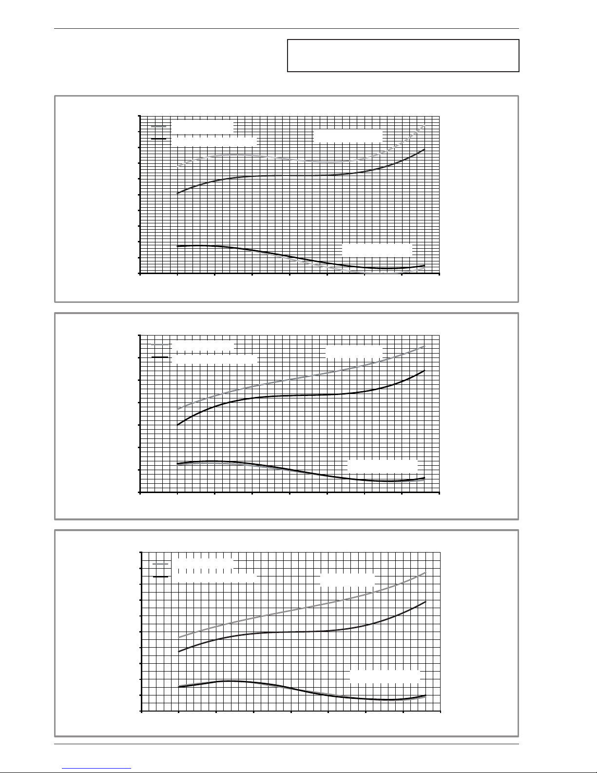
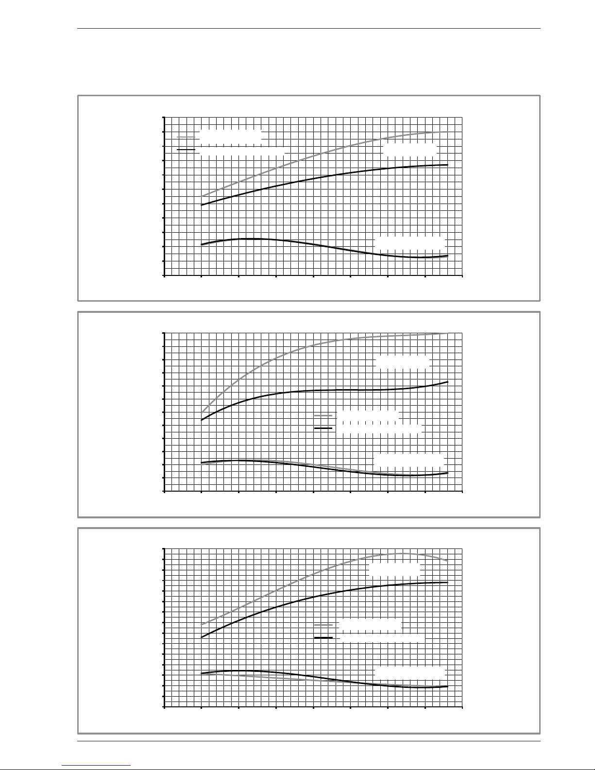
1.4 Heating power curve
1,00
1,50
2,00
2,50
3,00
3,50
4,00
4,50
5,00
5,50
6,00
-20 -15 -10 -5 0 5 10 15 20
1,00
2,00
3,00
4,00
5,00
6,00
7,00
8,00
-20 -15 -10 -5 0 5 10 15 20
1,00
2,00
3,00
4,00
5,00
6,00
7,00
8,00
9,00
10,00
11,00
-20 -15 -10 -5 0 5 10 15 20
Values according to standard EN 14511, for which it is necessary
to add the power absorbed by the heating circulation pump.
S5
S6
S8
Floor heating system
Very low temperature radiator
Heat output
Power absorbed
Outside temperature (°C)
Power (kW)
Floor heating system
Very low temperature radiator
Heat output
Power absorbed
Outside temperature (°C)
Power (kW)
Floor heating system
Very low temperature radiator
Heat output
Power absorbed
Outside temperature (°C)
Power (kW)
Installation and operating manual "1303 - EN"
Heat pump Alfea S
- 6 -
Page 7
1,00
2,00
3,00
4,00
5,00
6,00
7,00
8,00
9,00
10,00
11,00
12,00
-20 -15 -10 -5 0 5 10 15 20
2,00
3,00
4,00
5,00
6,00
7,00
8,00
9,00
10,00
11,00
12,00
13,00
14,00
-20 -15 -10 -5 0 5 10 15 20
2,00
3,00
4,00
5,00
6,00
7,00
8,00
9,00
10,00
11,00
12,00
13,00
14,00
15,00
16,00
17,00
-20 -15 -10 -5 0 5 10 15 20
S10
S13
S16
Floor heating system
Very low temperature radiator
Heat output
Power absorbed
Outside temperature (°C)
Power (kW)
Floor heating system
Very low temperature radiator
Heat output
Power absorbed
Outside temperature (°C)
Power (kW)
Floor heating system
Very low temperature radiator
Heat output
Power absorbed
Outside temperature (°C)
Power (kW)
Installation and operating manual "1303 - EN" - 7 -
Heat pump Alfea S
Page 8
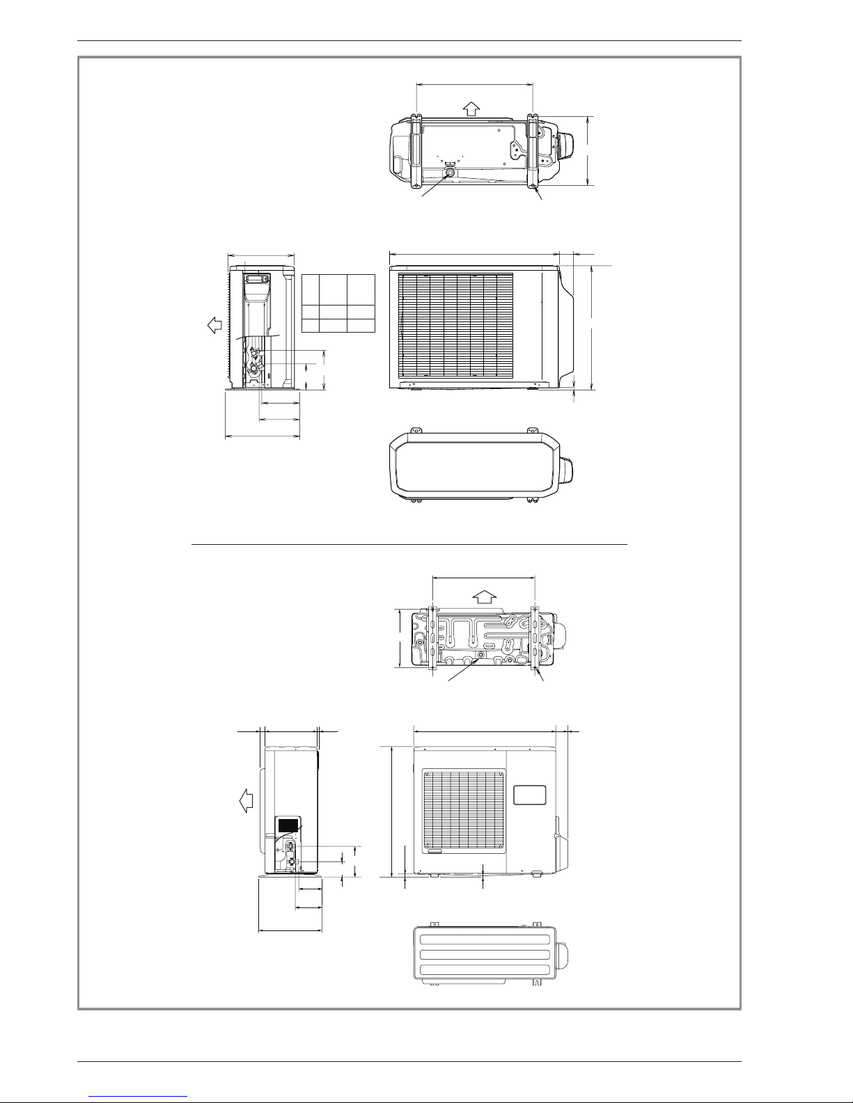
77900
830
21
9
400
33031 12
196
147
170
99
3/8”
5/8”
370
650
AIR
Front view
Side view
Top view
AIR
Overflow hole (Ø 20) 4 Ø 10)Holes
Sight of lower part
540
66790
10
347
300
189
177
578
320
121
184
A
B
A
B
S8
S5
S6
1/4” 1/4”
1/2” 5/8”
Top view
Front view
Sight of lower part
Overflow hole (Ø 20)
4 Holes Ø 10)
AIR
Side view
AIR
Figure 1 - Dimensions in mm
" Outside unit,
Model S5, S6, S8
" Outside unit,
Model S10
Installation and operating manual "1303 - EN"
Heat pump Alfea S
- 8 -
Page 9
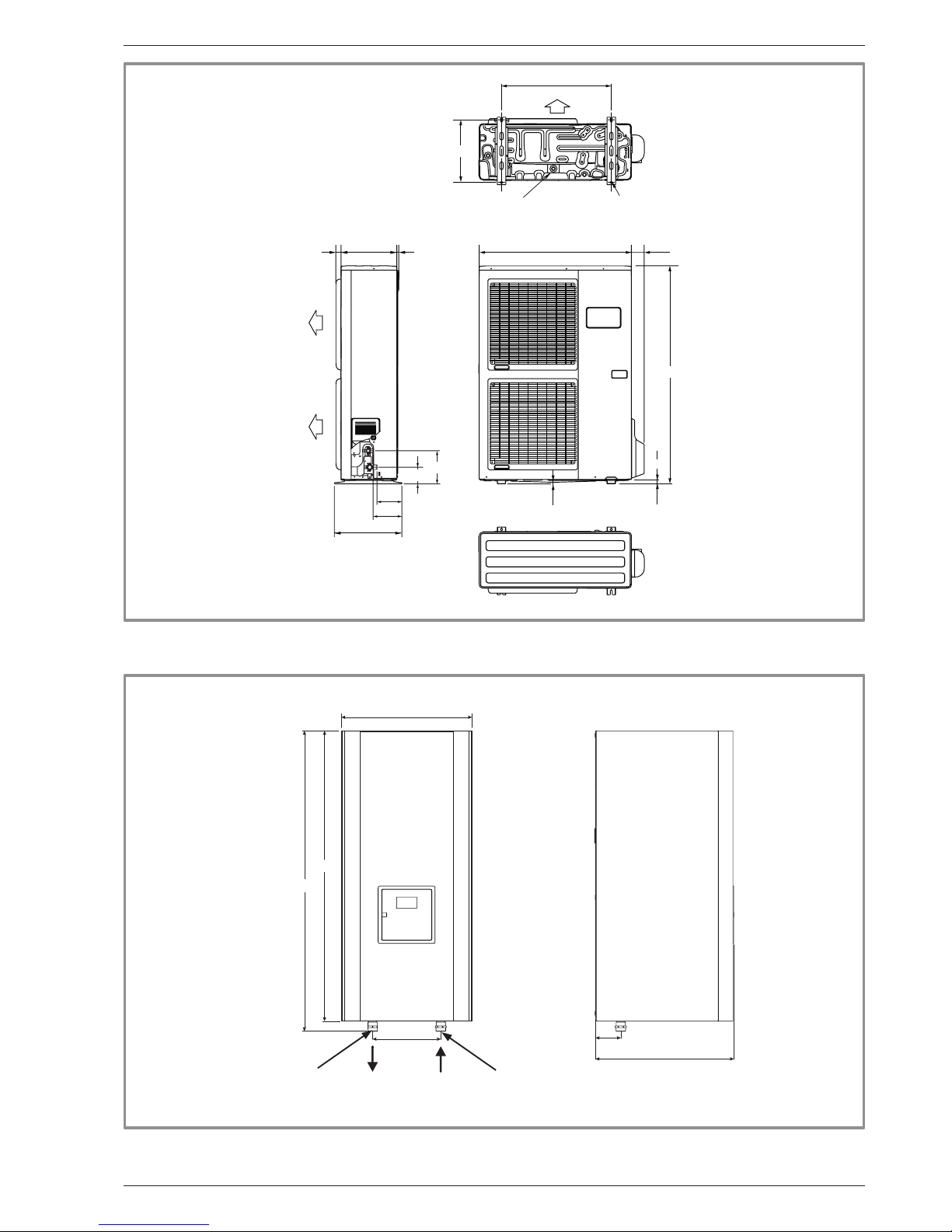
480
88
235
450
1034
1000
31 77900330 12
9
400
650
21
1290
147
170
196
370
99
3/8”
5/8”
Air
Overflow hole (Ø 20) 4 Ø 10)Holes
Top view
Front view
Sight of lower part
Side view
Air
Air
" Outside unit,
Model S13, S16
Figure 2 - Dimensions in mm
Figure 3 - Dimensions in mm
" Hydraulic module
Outside unit
ø M 26x34
Heating return
ø M 26x34
Front view
Side view
Installation and operating manual "1303 - EN" - 9 -
Heat pump Alfea S
Page 10
mbar
600
500
400
300
200
100
0
0,4 0,6 0,8 1 1,2 1,4 1,6 1,8
m
3
/h
3
2
1
Figure 4 - Hydraulic pressures and ow rates available
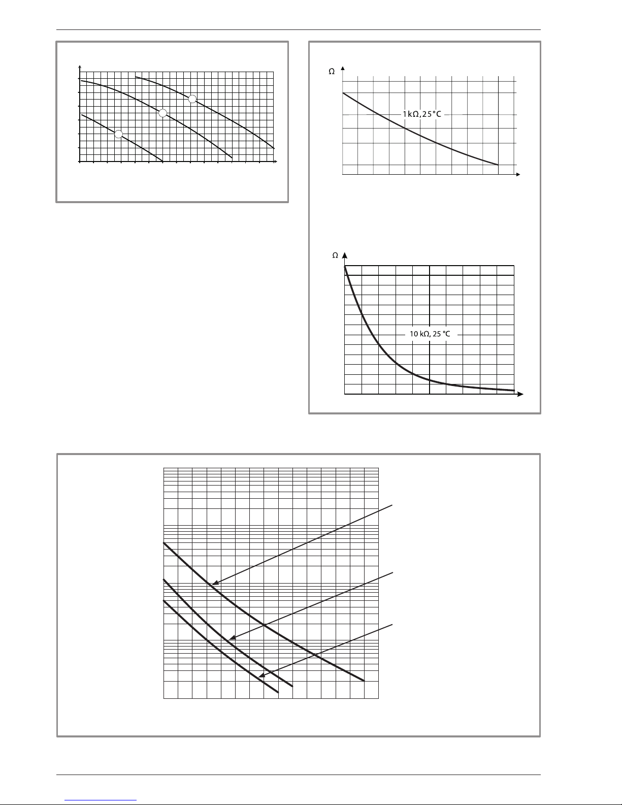
-50
1000
10000
43907
2490
338
-25 0 25 50 75
° C
0
2500
5000
7500
10000
12500
15000
17500
20000
22500
25000
27500
30000
32500
0 10 20 30 40 50 60 70 80 90 100
°C
Outdoor sensor QAC34
Heat pump return sensor
Heat pump ow sensor
Figure 5 - Ohmic values of the sensors
(Hydraulic module)
Figure 6 - Ohmic values of the sensors (outside unit)
-20 -10 0 10 20 30 40 50 60 70 80 90 100 110 120 130
10000
1000
100
10
1
- Compressor
- Discharge
- Condensation
- Evaporator outlet
- Evaporator center
- Compressor casing
- Outside
Temperature °C
Ohmic value (kΩ)
1mbar = 10 mmCE = 100 Pa
Installation and operating manual "1303 - EN"
Heat pump Alfea S
- 10 -
Page 11
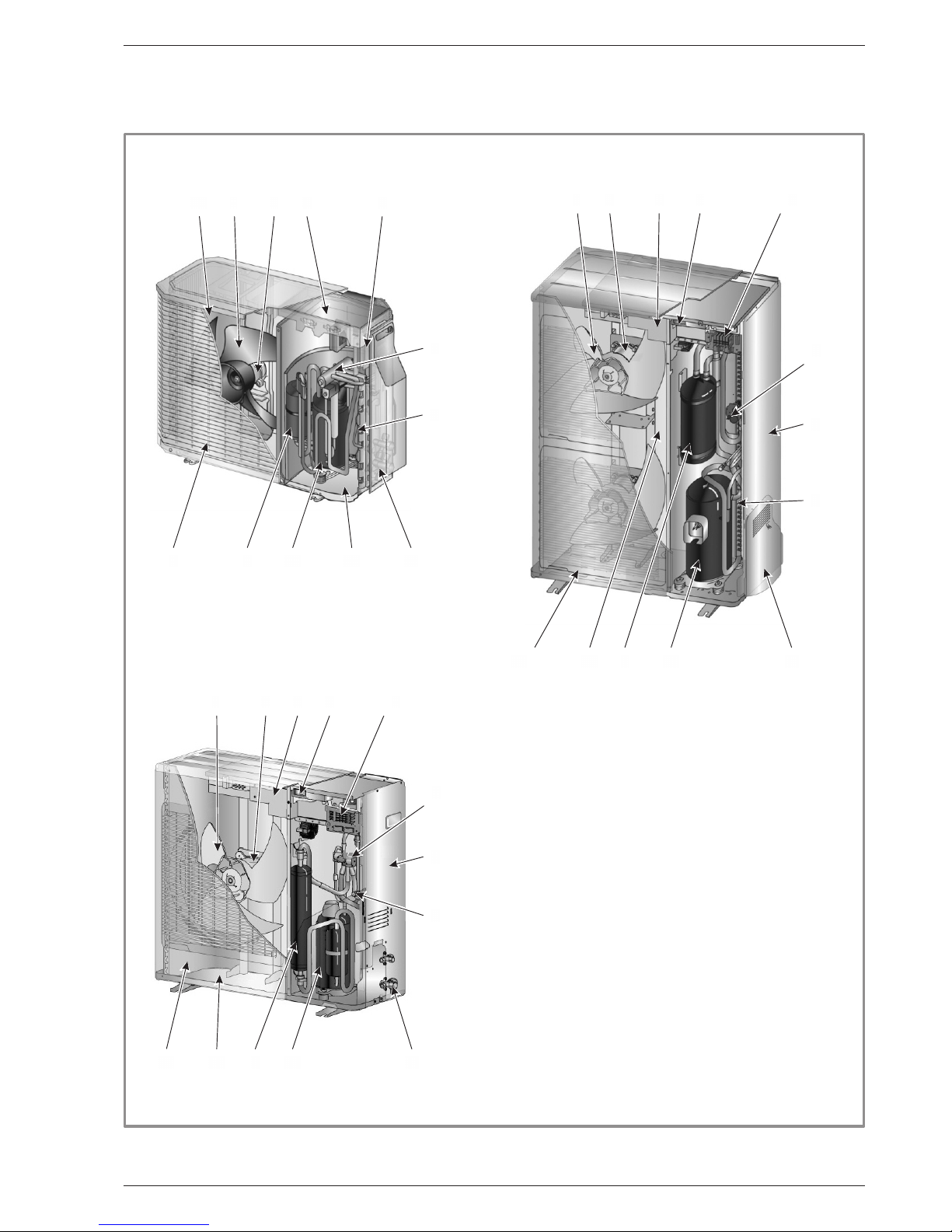
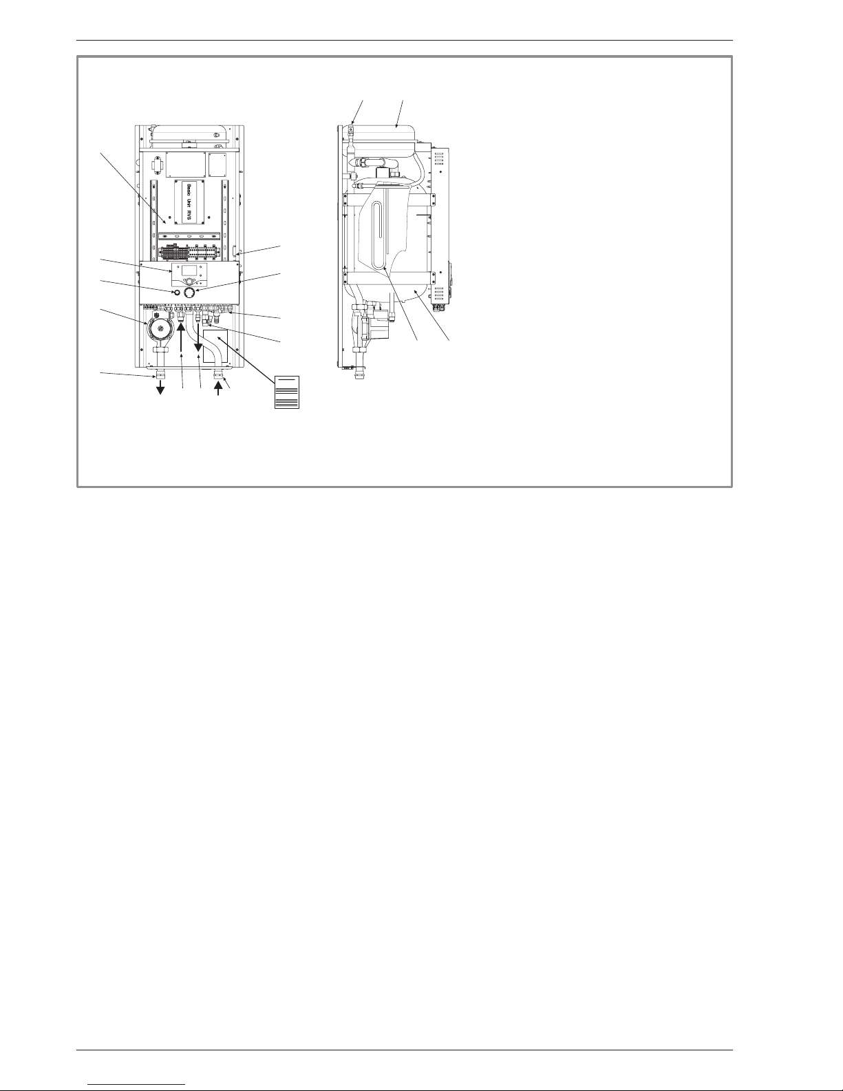
1.5 Description
13
1
2
12 1110
9
8
7
6
5
3
13
1
2
12 1110
9
8
7
6
5
4
3
13
1
2
12 1110
9
8
7
6
5
4
3
Legend :
1 - Low-noise, high-output coil.
2 - Electric variable speed "inverter" motor.
3 - "Inverter" control module.
4 - Vacuum start (pump down) and control light.
5 - Connection terminal blocks
(power and interconnection).
6 - Refrigerant accumulator bottle.
7 - Cycle reversing valve.
8 - Anti-corrosion treated bodywork.
9 - Electronic expansion valve.
10 - Noise and temperature insulated "inverter"
compressor.
11 - Refrigeration connection valves (ared connectors)
with protective caps.
12 - Holding tank with condensate drain hole.
13 - High-performance exchange surface evaporator ;
anti-corrosion treated hydrophilic aluminium ns and
grooved copper tubes.
" Model S5, S6, S8 " Model S13, S16
" Model S10
Figure 7 - Outside unit components
Installation and operating manual "1303 - EN" - 11 -
Heat pump Alfea S
Page 12
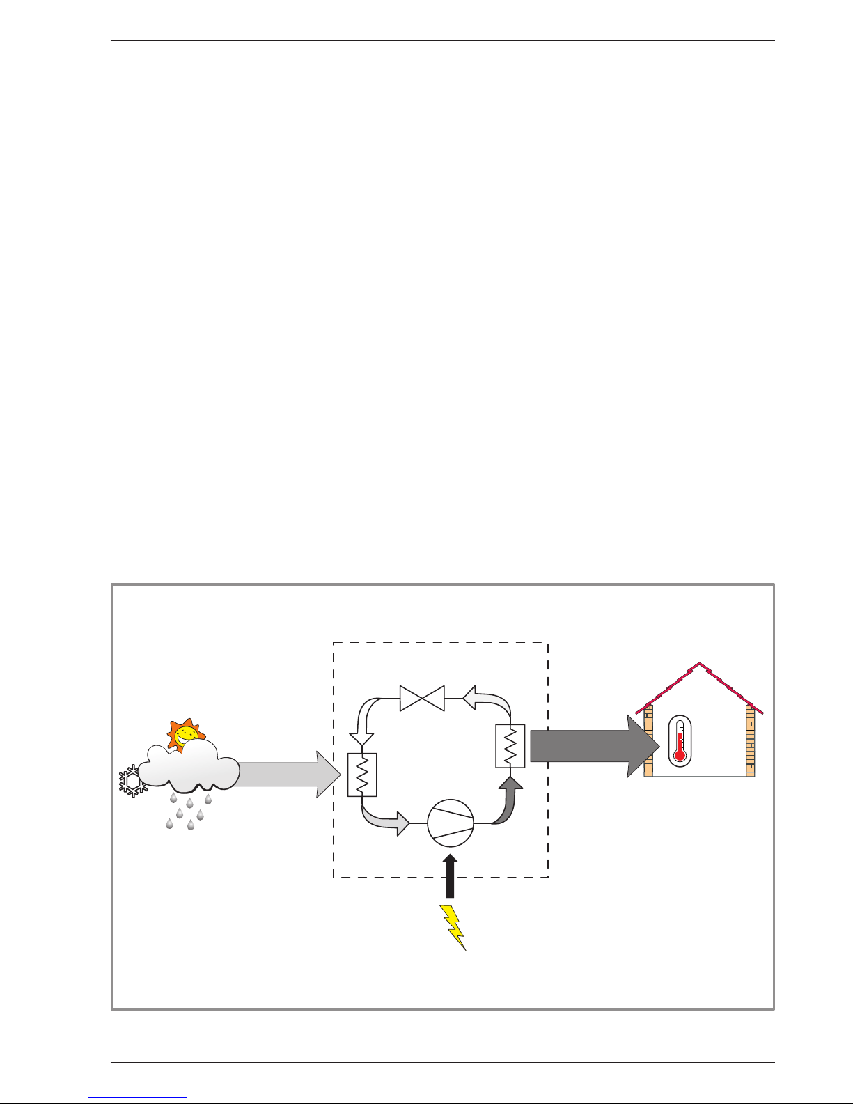
1.6 Operating principle
The heat pump transmits the energy contained in the
surrounding air into the dwelling to be heated.
The heat pump consists of four main elements, in which
a refrigerant uid (R410A) circulates.
- In the evaporator (rep. 13, gure 7, page 11) :
The energy is taken from the surrounding air and is
transmitted to the refrigerant. Because it has a low
boiling point, it changes from the liquid state to the
vapour state, even in cold weather (down to -15 °C
outside temperature).
- In the compressor (rep. 10, gure 7 , page 11) :
The vaporised refrigerant brought to high pressure
and takes on more calories.
- In the condenser (rep. 15, gure 8, page 12) :
The energy in the refrigerant is transmitted to the
heating circuit. The refrigerant returns to liquid state.
- In the expansion valve (rep. 9, gure 7, page 11) :
The liqueed refrigerant is brought back to low pressure
and returns to its initial temperature and pressure.
The heat pump is equipped with a controller, which
controls the internal temperature based on the outside
temperature measurement and governed by the
temperature control.
The room thermostat (optional) provides a corrective
action for the temperature control.
The hydraulic module is equipped with an electric backups system, which is triggered to provide additional heat
during the coldest periods.
1
2
3
4
5
6
7
8
9
10
11
12
13 14
15
16
Front view
Side view
Identification plate
Legend :
1 - Electric box.
2 - Regulator / User interface.
3 - Start/stop switch.
4 - Heating circulation pump.
5 - Initial heating.
6 - Gas refrigeration connection.
7 - Fluid refrigeration connection.
8 - Heating return.
9 - Drain valve.
10 - Safety valve.
11 - Safety thermostat.
12 - Manometer.
13 - Manual drainer.
14 - Expansion vessel.
15 - Condenser.
16 - Electric back-ups.
Regulation functions
- The heating circuit’s initial temperature is controlled by
the temperature control.
- The power of the outside unit is modulated according
to initial heating temperature via the “inverter”
compressor.
- Control of the electric back-up heating.
- The daily timer program enables you to dene
the periods for comfortable or reduced ambient
temperature.
- Summer/winter mode switchover is automatic.
- Control of the supplementary boiler* (the electric backups are deactivated).
- The room thermostat* (optional) provides a corrective
action for the temperature control.
- Control of a second heating circuit*.
- Domestic hot water: Heating time programme, control
of the operation of the DHW circulation pump.
- Control of swimming pool heating*.
- Managing the cooling.
Protection functions
- Anti-legionella cycle for domestic hot water.
*
If the heat pump is equipped with optional equipment and
the associated kits.
Figure 8 - Hydraulic module components
Installation and operating manual "1303 - EN"
Heat pump Alfea S
- 12 -
Page 13
Domestic hot water (DHW) operating principle
Two domestic hot water (DHW) temperatures can be
parametered: comfort temperature (line 1610 to 50 °C)
and reduced temperature (line 1612 to 25 °C).
Setting for reduced temperature can be useful to prevent
the DHW from switching on too often and for too long
during the day.
The production of domestic hot water (DHW) is triggered
when the temperature in the tank falls 7°C (setting from
line 5024) below the set temperature.
The heat pump produces the domestic hot water, which
is then supplemented, if required, by electrical backup
heating from the tank.
To ensure a DHW setting over 45°C, the electrical
backup heating or the boiler must be left on.
Depending on how the parameter (1620) is set, comfort
temperature can be reached 24h/day or only at night or
depending on the heat pump programme.
If the contract concluded with the energy provider
includes a subscription to day/night tariff, the electrical
backup is subordinate to the supplier’s power tariff and
the comfort temperature may only be reached at night.
If no particular contract is concluded, the comfort
temperature can be reached at any time, including
during the day.
The production of DHW takes priority over heating;
nevertheless the production of DHW is controlled by
cycles that control the times assigned to the heating
and the production of DHW in the event of simultaneous
demand.
A function to switch from "reduced" to "comfort" is
provided on the front of the user interface (see ref. 1,
gure 39, page 31 ).
This DHW boost enables the DHW to be heated to the
comfort temperature at any time during the day. The
boost function is cancelled automatically when the
demand for hot water has been met.
If the heating installation is equipped with a DHW
circulation pump, the pump’s operation during DHW
cycles can be parametered.
Anti-legionella cycles can be programmed.
• Fan convectors with integrated control system
Do not use a room sensor in the area.
Figure 9 - Heat pump operating principle
Ev
Dt
Cn
Cp
1 kW
COP 4
4 kW
20 °C
PAC
PAC - Heat pump
Ev - Evaporator
Cp - Compressor
Cn - Condenser
Dt - Expansion valve
Energy from the air
Heat produced
Electrical
energy
consumed
Installation and operating manual "1303 - EN" - 13 -
Heat pump Alfea S
Page 14
2 Installation
2.1 Regulation installation
and maintenance conditions
The appliance must be installed and the maintained by an
approved professional in accordance with the prevailing
regulations and code of practice, in particular :
The legislation on the handling of refrigerants.
2.2 Unpacking and reservations
2.2.1 Receipt
Carefully check, in the carrier’s presence, the general
appearance of the appliances and check that the outside
unit is not laid on its side or back.
In the case of any dispute, state any appropriate
reservations to the carrier in writing within 48 hours and
send a copy of this letter to the After-Sales service.
2.2.2 Handling
The outside unit should not be laid on its side or back
during transport.
Laying the unit down during transport is likely to damage
the internal tubes and the compressor suspensions.
Any damage caused by transportation of the unit lying
down is not covered by the warranty.
If necessary the outside unit may be tilted only during
manual handling (to go through a door or use a
staircase).
This operation must be conducted very carefully and
the appliance must be immediately restored to upright
position.
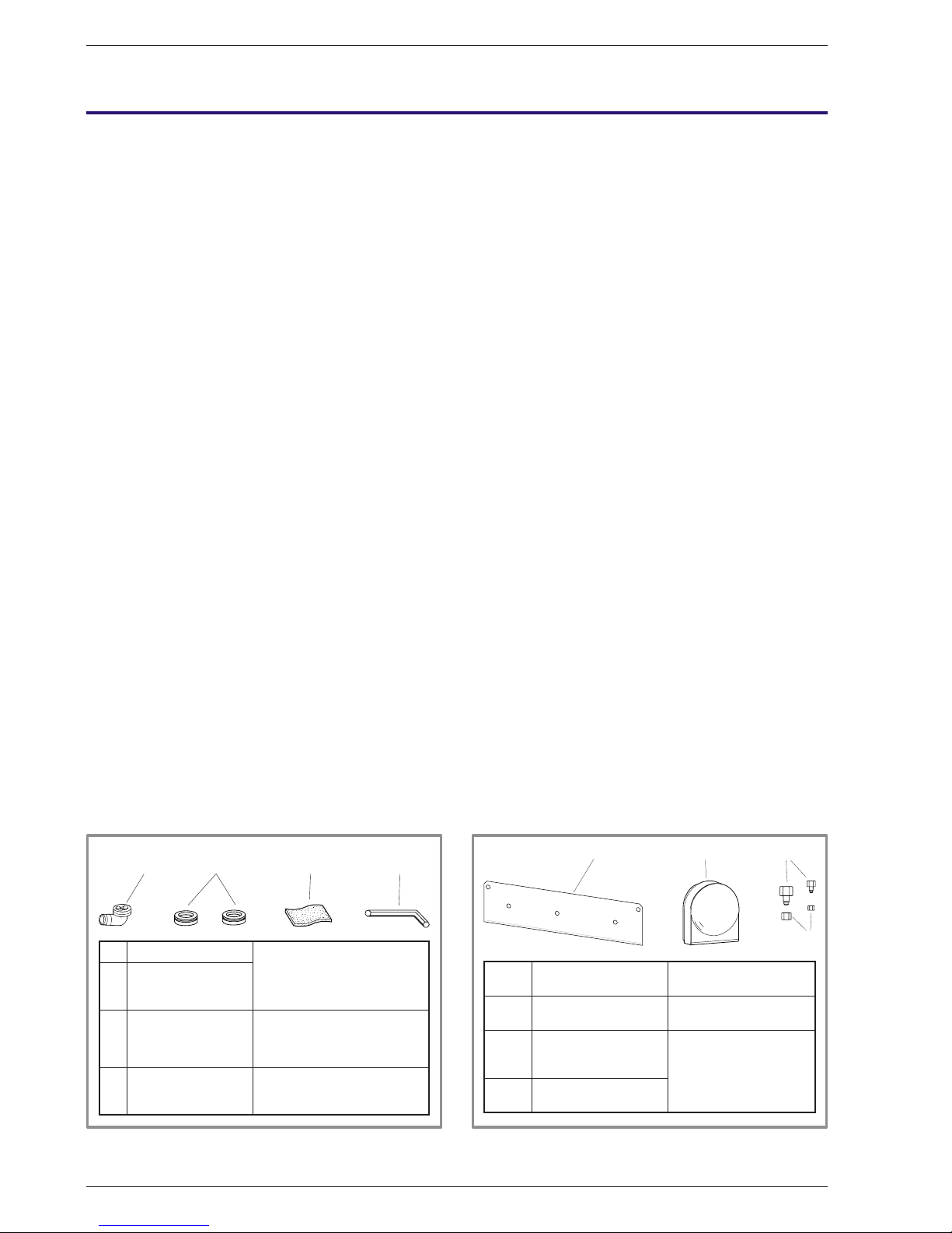
2.2.3 Accessories provided
Accessories provided with the outside unit (gure 10).
Accessories provided with the hydraulic module
(gure 11).
2.3 Installation position
The choice of the position for installation is particularly
important insofar as any later movement is a delicate
operation requiring the intervention of a qualied
person.
Choose the site of the outside unit and the hydraulic
module after discussion with the customer.
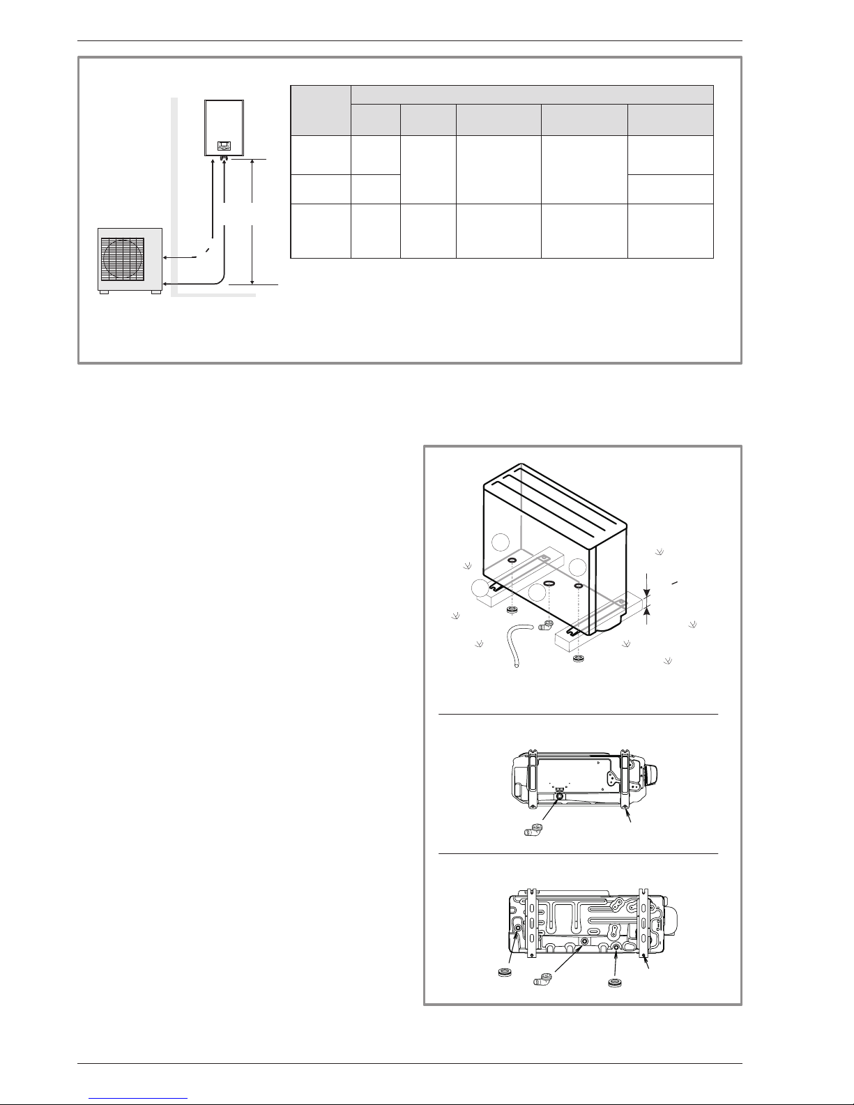
Observe the maximum and minimum distances between
the hydraulic module and the outside unit (gure 13);
the guarantee of the performances and the system’s
service life depend on this.
2.4 Installation of the outside unit
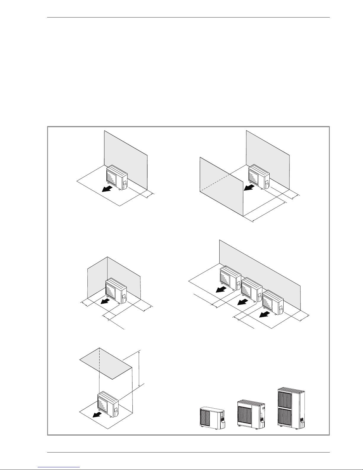
2.4.1 Installation precautions
" The outside unit must only be installed outside
(outdoors). If a shelter is required, it must have
broad openings on the 4 walls and observe the
installation clearances (gure 12).
• Choose a site that is preferably sunny and sheltered
from strong cold predominant winds (mistral,
tramontana, etc…).
• The unit must be easily accessible for future installation
and maintenance work (gure 12).
• Ensure that it is possible to make the connections to
the hydraulic module easily.
• The outside unit is able to withstand bad weather but
avoid installing in a position where it is likely to be
exposed to signicant dirt or owing water (under a
defective gutter for example).
1
3
2
4
1 Elbow
For draining away the
condensates
2
Plug (x 2)
(Depending on the
model)
3
Flexible insulation
plate
For lling the empty space
at the input to the
interconnection cable
4 Hex / Allen key To open the valves
Figure 10 - Accessories provided
with the outside unit
8
5 6 7
5 Bracket
To secure the hydraulic
model
6 Outdoor sensor
To monitor the outside
temp
7
Adaptater
1/2" - 5/8" and/or
1/4" - 3/8"
To connect the ared
connection and the
hydraulic model
8
Nut 1/2"
and/or 1/4"
Figure 11 - Accessories provided
with the hydraulic module
Installation and operating manual "1303 - EN"
Heat pump Alfea S
- 14 -
Page 15
• Water may drain away from the outside unit when it
is operating. Do not install the appliance on a paved
terrace; choose a well-drained place (e.g. gravel
or sand). If the installation is in an area where the
temperature can be lower than 0°C for a long period,
check that the presence of ice does not present any
danger. A drainage pipe can also be connected to
outside unit (see para 2.4.3, page 16).
• Nothing should obstruct the air circulation through the
evaporator and from the fan (gure 12).
• Keep the outside unit away from heat sources and
inammable products.
• Make sure the appliance not disturb the surrounding
area or users (noise level, draught generated, low
temperature of the air being blown out, with the risk of
freezing plants in its path).
• The surface supporting the outside unit should :
- be permeable (soil, gravel, etc),
- support its weight easily,
- provide a solid xing and
- not transmit any vibration to the dwelling.
Anti-vibratory blocks are available, please consult your
retailer.
• The wall brackets is strongly discouraged due to
vibration.
AIR
100 mm
100 mm
600 mm
100 to 300 mm
300 mm
300 mm
250 mm
For access
250 mm
For access
250 mm
For access
AIR
AIR
AIR
minimum
600 mm
AIR
Figure 12 - Minimum installation clearances around outside unit (all models)
Installation and operating manual "1303 - EN" - 15 -
Heat pump Alfea S
Page 16
DL
mini
5 m
DL
mini
5 m
2.4.2 Outside unit positioning
The outside unit must be raised at least 50 mm above
ground level. In areas prone to snow, this height should
be increased but should not exceed 1,5 m (gure 14).
- Fasten the outside unit by means of screws and
rubber tightening or toothed lock washers to avoid
their coming loose.
2.4.3 Condensate drain hose
(see gure 14).
If the use of a discharge pipe is imperative :
- Use the elbow provided (C) to connect a 16mm
diameter hose for draining away the condensate.
- Use the stopper or stoppers provided (B) to block the
opening of the condensate tank.
Allow for the condensate to ow away under the force of
gravity (waste water, rain water, gravel bed).
" If the installation is made in an area where
the temperature can be lower than 0°C for
a long period, provide the drain pipe with a
trace resistance to avoid it icing up. The trace
resistance must heat not only the pipe but
also the bottom of the appliance’s condensate
collection tank.
Figure 13 - Pipe diameters (in inches) and permissible lengths (in metres)
Heat
pump
Model
Gas and uid conduits
Gas Fluid
Minimum
length (L)
*Maximum
length (L)
**Maxi level
difference (D)
S5
S6
1/2"
1/4" 5 15
15
S8 5/8" 20
S10
S13
S16
5/8" 3/8" 5 20 30
* : Without additional charge of R410A.
** : Taking into account the possible additional load of refrigeration uid R410A
(see § 2.7.3, page 22).
S
B
C
B
H > 50 mm
*
(Ø 12 mm)
(Ø 10 mm)
Depending on the model
Depending on the model
* In regions subject to frequent snow,
(H) must be greater than the average snow layer
.
4 holes
4 holes
Figure 14 - Positioning of the outside unit, draining
away the condensate
Heat
pump
PAC
Outside unit
Installation and operating manual "1303 - EN"
Heat pump Alfea S
- 16 -
Page 17
B
B
(S)
5
5
4
90 mm
(S)
505 mm
240 mm
150 mm
200 mm
305 mm
2.5 Installing the hydraulic module
2.5.1 Installation precautions
• The room in which the appliance operates must comply
with the prevailing regulations.
• To facilitate maintenance and to allow access to the
various components, we recommend that you provide
sufcient space all around the hydraulic module
(gure 15).
• Be careful not to bring inammable gas near to the
heat pump during its installation, in particular when it
requires brazing.
The appliances are not reproof and should not therefore
be installed in a potentially explosive atmosphere.
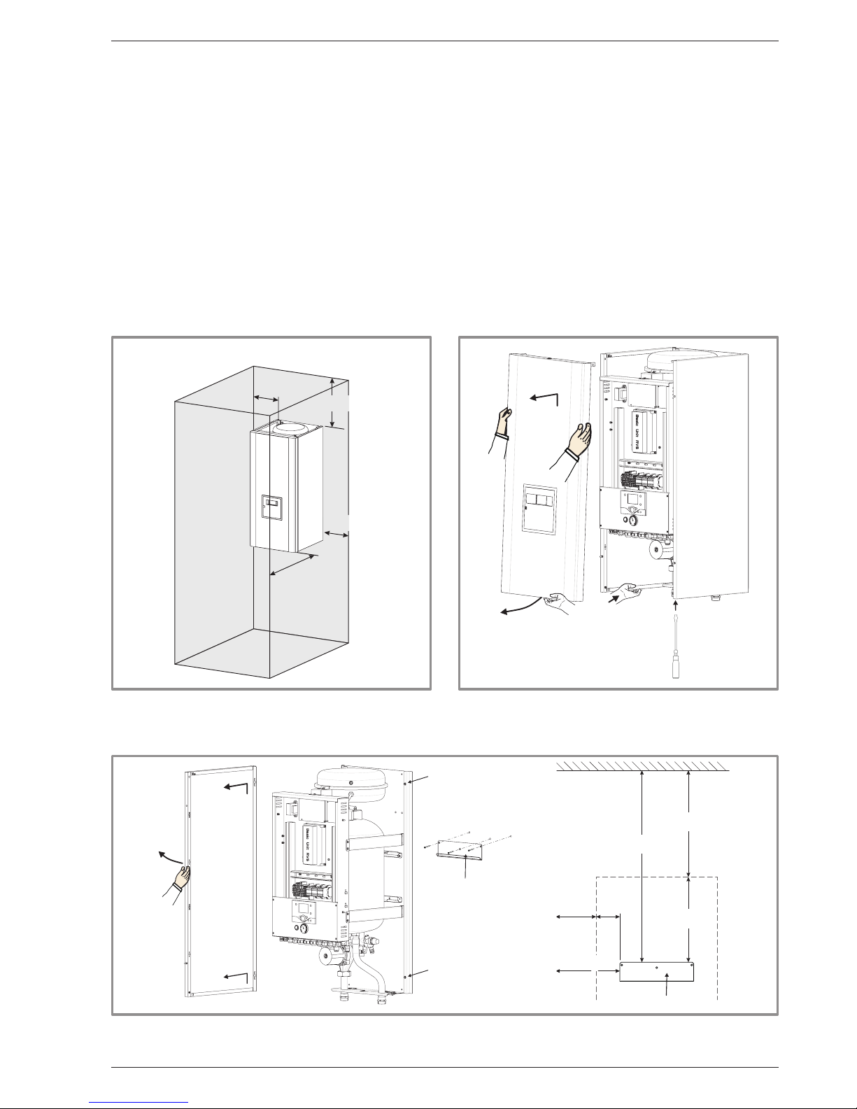
2.5.2 Positioning the hydraulic module
- 1, 2, 3 : Remove the front panel
(2 screws A, gure 16).
- 4, 5 : Remove the sides
(4 screws B, gure 17).
- Fix the support solidly (3 screws and plugs) to a at,
hard-wearing wall (not a light partition) ensuring that it
is correctly levelled.
- Hook the appliance onto its support.
- Ret the sides.
- Ret the front facing.
200 mm
1000 mm
150 mm
150 mm
1
3
2
A
Figure 15 - Minimum installation clearances
around the hydraulic module
and distances to the combustible partitions
Figure 16 - Removing the front facing
Figure 17 - Removing the sides and xing the support (S)
Installation and operating manual "1303 - EN" - 17 -
Heat pump Alfea S
Page 18
2.6 Refrigeration connections
" This appliance uses refrigerant R410A.
Comply with the legislation for handling refrigeration
uids.
2.6.1 Rules and precautions
• After every intervention on the refrigeration circuit and
before nal connection, take care to replace the plugs
in order to avoid any pollution from the refrigeration
circuit.
• Tools
- Set of manometers with hoses exclusively reserved
for HFCs (Hydrouorocarbons).
- Vacuum pump specially for HFCs.
- Provision on using tools that have been in contact with
HCFCs (R22 for example) or CFCs.
- Use of a traditional vacuum pump is authorized if, and
only if, it is tted with a non-return valve on the suction
side.
The manufacturer declines any liability with regard to the
guarantee if the above instructions are not observed.
• Flared connections
" Lubrication with mineral oil (for R12, R22) is
forbidden.
- Only lubricate with polyolester refrigeration oil (POE).
If POE is not available, t without lubrication.
• Brazing on the refrigeration circuit (if necessary)
- Silver brazing (40% minimum recommended).
- Brazing only under dry nitrogen internal ux.
• To eliminate any lings in the pipes, use dry nitrogen
to avoid introducing any humidity that may adversely
affect the appliances operation. In general, take every
precaution to avoid humidity penetrating into the
appliance.
• Use pipe insulators resistant to temperatures over
120°C. In addition if the humidity level in areas where
the refrigeration pipes are installed is expected to
exceed 70%, protect the pipes with pipe insulators.
Use an insulating material thicker than 15mm if the
humidity level is 70~80%, and an insulating material
thicker than 20mm if the humidity exceeds 80%. If the
recommended thicknesses are not observed under the
conditions described above, condensation will form on
the surface of the insulation material. Lastly, take care
to use pipe insulators whose thermal conductivity is
0.045 W/mK or less when the temperature is 20°C. The
insulation must be impermeable to resist the passage
of steam during the defrosting cycles (breglass wool
is prohibited).
2.6.2 Refrigeration connections
The outside unit must be connected to the hydraulic
module with copper pipes and connections (refrigeration
quality), insulated separately.
Comply with the pipe diameters and the permitted pipe
lengths (gure 13).
The minimum length of the refrigeration connections
is 5m for correct operation (except model S5 and S6,
see gure 13).
The appliance will be excluded from guarantee if it is
used with refrigeration connections less than 5m long
(models S8, S10, S13, S16).
Manipulate the pipes and take them through walls with
protective plugs in place.
If the distance between the outside unit and the hydraulic
module exceeds the length of the maximum conduits
indicated in the table, an additional charge of R410A
must be loaded.
The quantity of R410A added must be adapted to the
length of the refrigeration circuit in order to the heat
pump’s performance without damaging the compressor
(gure 23).
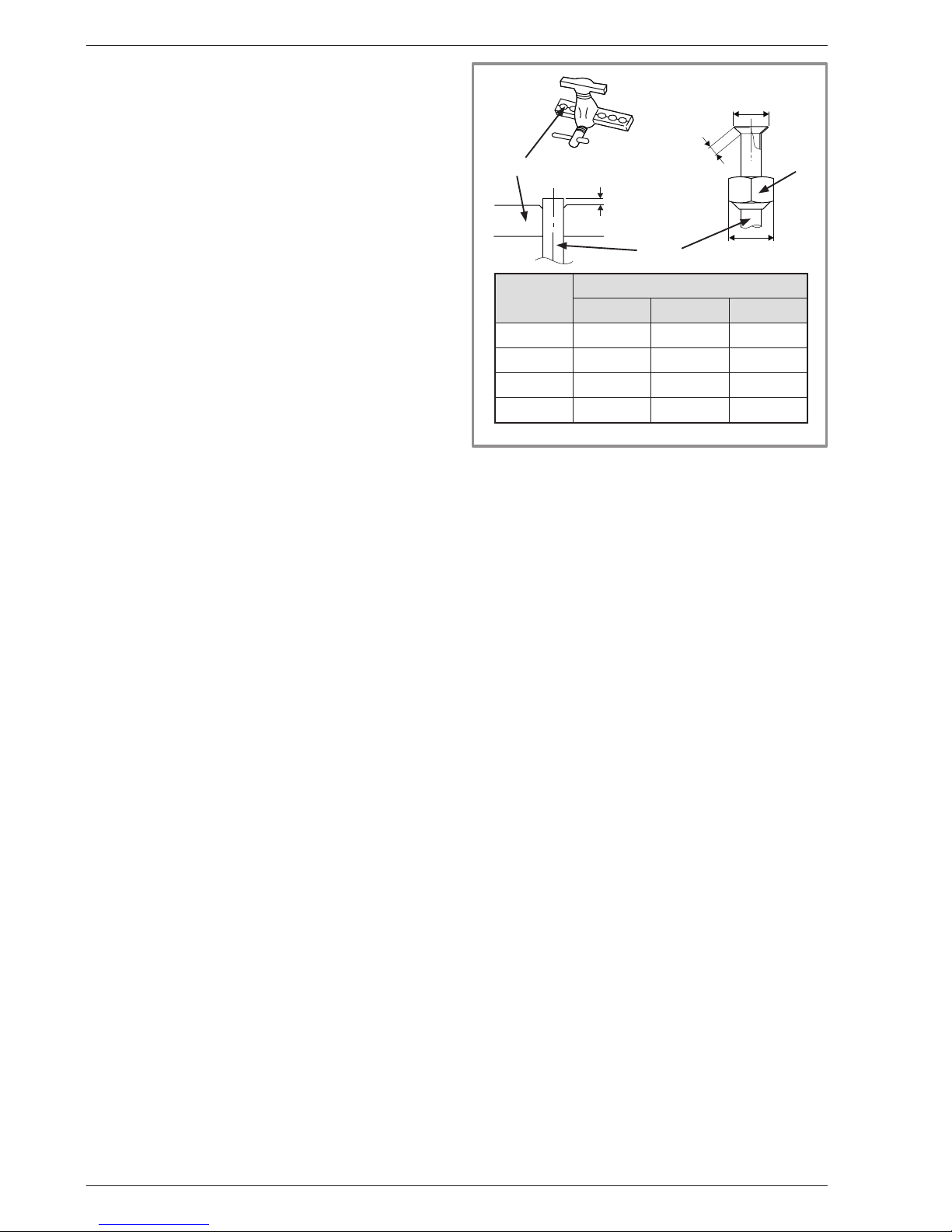
2.6.3 Creating the arings
- Cut the pipe to an appropriate length with a pipe-cutter
without deforming it.
- Carefully deburr it, holding the pipe towards the bottom
to avoid introducing lings into the pipe.
- Remove the ared connection nut situated on the valve
to be connected and slip the pipe into the nut.
- Proceed to are, letting the pipe overow the aring
tool.
- After aring, check the condition of the working radius
(L). This must not show any scratch or trace of any
fracturing. Also check the dimension (B).
Figure 18 - Flaring for are connections
Flaring tool
Hose
Flare
nut
B
L
C
ø Hose dimensions in mm
L B
0
/
-0,4
C
6,35 (1/4") 1,8 à 2 9,1 17
9,52 (3/8") 2,5 à 2,7 13,2 22
12,7 (1/2") 2,6 à 2,9 16,6 26
15,88 (5/8") 2,9 à 3,1 19,7 29
Installation and operating manual "1303 - EN"
Heat pump Alfea S
- 18 -
Page 19

2.6.4 Shaping the refrigeration pipes
The refrigeration pipes must be shaped only on a
bending machine or with a bending spring in order to
avoid any risk of crushing or breaking them.
" Warning
• Remove the insulation material locally to bend the
pipes.
• Do not bend the copper to any angle over 90°.
• Never bend pipes more than 3 times in the same
position otherwise traces of fracturing may appear
(from strain-hardening the metal).
2.6.5 Connecting the ared connections
" The small pipe must always be connected before
the large one.
" Take particular care positioning the tube opposite
its connector so as not to risk damaging the
threads. A carefully aligned connector can be
tted easily by hand without much force being
required.
" The refrigeration circuit is very sensitive to dust
and humidity: check that the area around the
connection is clean and dry before removing the
plugs protecting the refrigeration connectors.
Liquid valve
Flare nut
Liquid refrigeration connexion
Diameter D2
“Gas” refrigeration connexion
D1 Diameter
Gas valve
Flare nut
Flare nut
Flare nut
Adapter R2,
depending
on the model
Adapter R1,
depending
on the model
Outside
unit
Hydraulic
module
Outside unit
connections
Diameter of
refrigeration
connections
Male-female adapter
(reduction)
Hydraulic module
connections
Model S5
Model S6
Gas 1/2" (D1) 1/2" (R1) 1/2" - 5/8" 5/8"
Fluid 1/4" (D2) 1/4" (R2) 1/4" - 3/8" 3/8"
Model S8
Gas 5/8" (D1) 5/8" none 5/8"
Fluid 1/4" (D2) 1/4" (R2) 1/4" - 3/8" 3/8"
Model S10
Model S13
Model S16
Gas 5/8" (D1) 5/8" none 5/8"
Fluid 3/8" (D2) 3/8" none 3/8"
Figure 19 - Connecting the ared connections
Installation and operating manual "1303 - EN" - 19 -
Heat pump Alfea S
Page 20

- Depending on the case, connect an adapter (reducer)
1/4’’- 3/8’’ or 1/2’’- 5/8’’ (see gure 19).
- Remove the plugs from the pipes and the refrigeration
connections.
- Present the pipe to the ared connector and screw the
nut by hand while holding the connector with a wrench
until contact.
- Comply with the recommended tightening torques
(see gure 21).
Figure 20 - Prevention of gas leaks
Figure 21 - Tightening torque
Coat the ared surface
with POE refrigeration oil.
Do not use mineral oil.
Designation Tightening torque
Flare nut 6,35 mm (1/4") 14 to 18 Nm
Flare nut 9,52 mm (3/8") 33 to 42 Nm
Flare nut 12,7 mm (1/2") 50 to 62 Nm
Flare nut 15,88 mm (5/8") 63 to 77 Nm
Plug (A) 3/8", 1/4" 20 to 25 Nm
Plug (A) 1/2" 25 to 30 Nm
Plug (A) 5/8" 30 to 35 Nm
Plug (B) 3/8", 5/8" 10 to 12 Nm
Plug (B) 1/2", 1/4" 12,5 to 16 Nm
Holding wrench
Torque wrench
Installation and operating manual "1303 - EN"
Heat pump Alfea S
- 20 -
Page 21

2.7 Filling the installation with gas
" This operation is reserved for installers familiar
with the legislation for handling refrigeration
uids.
" Creating a vacuum with a vacuum pump is
essential.
" Never use equipment used beforehand with any
refrigerant other than a HFC.
2.7.1 Creating a vacuum and lling
the refrigeration connections with gas
(see gure 22).
- Remove the protective plugs (B) from the charging
hole (Schrader) in the gas valve (large diameter).
- Connect the blue hose (on the side with a valve
pusher in good condition) from the set of manometers
(manifold).
- Connect the yellow hose to a vacuum pump and open
the blue valve on the set of manometers.
- Create a vacuum until the residual pressure in the
circuit falls below 0.01 bar.
- Let the pump continue to operate for another 15
minutes after reaching the vacuum.
- Close the blue valve on the set of manometers and
then stop the vacuum pump without disconnecting
any of the hoses in place.
- Wait 10 minutes. If the pressure rises during this
10-minute period, there is a leak in the circuit. Trace it
and repair it: then start again.
When the pressure has remained stable for 10
minutes after the vacuum pump stops, the circuit
is considered to be gas-tight.
- Remove the access plugs (A) from the valve controls.
" If an additional charge is requires, add the
additional charge before lling the hydraulic
module with gas. Please refer to the section
(“Additional charge”, page 22).
- First of all fully open the small valve and then the
large one using a hex key (counterclockwise direction)
without forcing excessively against the stop.
- Remove the blue hose rapidly.
- Ret the 2 plugs and tighten them to the recommended
tightening torque (see gure 21).
The outside unit does not contain any additional
refrigerant, enabling the installation to be purged.
Flushing is strictly forbidden.
2.7.2 Sealing test
Once the refrigeration circuit has been gassed as
described above, check that all the refrigeration
connectors are gas-tight:
6 connectors for models S5 and S6, 5 connectors for
model S8 and 4 connectors for models S10, S13 and
S16.
The sealing test must be performed with an approved
gas detector.
If the arings have been made correctly, there should
be no leaks.
" If there is a leak, make the connection again.
Lo
Hi
Manometer kit
(manifold)
Vacuum pump
Service hose
Low
pressure
High
pressure
Gas valve
Vacuum meter
Refrigeration connexion
Plug (A)
Hex / Allen key of 4 mm
3-way valve
Load orifice
Plug (B)
Service hose (blue)
fitted with valve push-button
Figure 22 - Extraction under vacuum and gassing
Installation and operating manual "1303 - EN" - 21 -
Heat pump Alfea S
Page 22

2.7.3 Additional charge
The charge in the outside units corresponds to the
maximum distances between the outside unit and the
hydraulic module dened in gure 13. If the distances
are greater, an additional charge of R410A is required.
The additional charge depends on the distance between
the outside unit and the hydraulic module for each type
of appliance (gure 23). The additional charge of R410A
must necessarily be made by an approved refrigeration
engineer.
• Example for a heat pump model S16
An outside unit 32m away from the hydraulic module
will require an additional charge of :
Additional charge = (32 - 20) x 40 = 480 g.
The charge must be introduced after creating the
vacuum and before the hydraulic module is lled with
gas, as follows :
- Disconnect the vacuum pump (yellow hose) and
connect a bottle of R410A instead in the uid
extraction position.
- Open the bottle’s valve.
- Bleed the yellow hose by loosening it slightly on the
manifold side.
- Place the bottle on scales with a minimum accuracy of
10g. Note the weight.
- Carefully open the blue valve slightly and check the
value shown on the scales.
- As soon as the value displayed has dropped by the
value for the calculated additional charge, close the
bottle and disconnect it.
- Then rapidly disconnect the hose connected to the
appliance.
- Proceed to ll the hydraulic module with gas.
" Warning
• Only use R410A !
• Only use tools suitable for R410A
(set of manometers).
• Always charge in the uid phase.
• Never exceed the length or the maximum difference
in level.
Model S5 - Model S6 20 g of R410A per additional meter
Length of the connections 15 m 20 m
Additional charge none 100 g
Model S8 20 g of R410A per additional meter
Length of the connections 15 m 20 m 25 m 30 m
Additional charge none 100 g 200 g 300 g
Model S10 40 g of R410A per additional meter
Length of the connections 15 m 20 m 30 m 40 m
Additional charge none 200 g 600 g 1000 g
Model S13 50 g of R410A per additional meter
Length of the connections 20 m 30 m 40 m
Additional charge none 500 g 1000 g
Model S16 40 g of R410A per additional meter
Length of the connections 20 m 30 m 40 m
Additional charge none 400 g 800 g
Figure 23 - Additional charge
R410A
Gas
Fluid
Figure 24 - Gas bottle R410A
Installation and operating manual "1303 - EN"
Heat pump Alfea S
- 22 -
Page 23

2.8 Connecting
the heating circuit hydraulically
2.8.1 General
The connection must comply with good trade practice
according to local building regulations.
The heating circulating pump is built into the hydraulic
module.
Connect the central heating pipes to the hydraulic
module, complying with the direction of circulation.
The diameter of the pipes between the hydraulic
module and the heating collector must be at least 1 inch
(26x34mm).
Calculate the diameter of the pipes according to the ow
rates and the lengths of the hydraulic systems.
Tightening torque : 15 to 35 N.m.
Use union connectors to facilitate removing the hydraulic
module.
Preferentially use connection hoses to avoid transmitting
noise and vibrations to the building.
Connect the drains from the drain valve and the safety
valve to the main sewer system.
Reminder: Seal everything when tting in accordance
with prevailing trade practice for plumbing work :
- Use suitable seals (bre seals, o-rings).
- Use Teon tape or hemp.
- Use sealing paste (synthetic depending on the case).
The use of glycol is not necessary. If you are using a
glycol/water mix, provide for an annual check on the
quantity of glycol.
In certain installations, the presence of different metals
can cause corrosion problems; the formation of metal
particles and sludge in the hydraulic circuit is then
seen.
In this case, it is advisable to use a corrosion inhibitor in
the proportions indicated by its manufacturer.
It is also necessary to ensure that the treated water
does not become aggressive.
2.8.2 Rinsing out the installation
Before connecting the hydraulic module to the
installation, rinse out the heating system correctly to
eliminate any particles that may affect the appliance’s
correct operation.
Do not use solvents or aromatic hydrocarbons (petrol,
parafn, etc.).
In the case of an old installation, provide a sufciently
large decanting pot with a drain on the return from the
boiler and at the lowest point in the system in order to
collect and remove the impurities.
Add an alkaline product to the water and a dispersant.
Rinse the installation several times before lling it
denitively.
2.8.3 Filling and purging the installation
Check the pipe xings, the tightness of the connectors
and the stability of the hydraulic module.
Check the direction in which the water is circulating and
that all the valves open.
Proceed to ll the installation.
Do not operate the circulating pump while lling. Open
all the drain valves in the installation and the bleed valve
for the hydraulic module to remove the air contained in
the conduits.
Close the drain and bleed valves and add water until the
pressure in the hydraulic circuit reaches 1.5 bar.
Check that the hydraulic circuit has been purged
correctly.
Check that there are no leaks and that the circulating
pumps are not seized (if need be, release them).
After the “Start-up” stage (see page 30), once the
machine has started, purge the hydraulic module again
(2 liters of water).
Figure 25 - Release of the
circulation pump
Figure 26 - Recommended
circulation speed (for radiator)
(P)
Figure 27 - Hydraulic
module bleeder valve
II
S5
S6
S8
S10
III
S13
S16
Installation and operating manual "1303 - EN" - 23 -
Heat pump Alfea S
Page 24

2.9 Electrical connections
Ensure that the general electrical power supply has
been cut off before starting any repair work.
2.9.1 Characteristic of the electrical supply
The electrical installation must be conducted in
accordance with the prevailing regulations.
The electrical connections must only be made when all
the other tting operations have been completed (xing,
assembly, etc.).
" Warning
The contract concluded with the energy provider must
be sufcient not only to cover the heat pump’s power
but also the combined sum of all the appliances likely to
be operating at the same time.
When the power is too low, check with your energy
provider the value subscribed to in your contract.
Never use a socket for the power supply.
The heat pump must be supplied with power by special
protected leads from the electric panel via 2-pole circuit
breakers specially dedicated to the heat pump :
Curve D for the outside unit, curve C for the electric
heating and domestic water back-ups (see tables on
page 25).
The electrical installation must necessarily be equipped
with a 30mA differential protection.
This appliance is intended to operate under a nominal
voltage of 230V +/- 10%, 50 Hz.
2.9.2 General remarks on electrical connections
It is essential to maintain the live-neutral polarity when
making the electrical connections.
Tighten the screws on the terminal blocks perfectly.
Unsufcient tightening can cause overheating, leading
to breakdown or even a re.
Use cable clamps to prevent the conductors from being
disconnected accidentally.
Connection to Earth and Earth bonding continuity are
essential.
• Connecting to screw terminals
Rigid wires (A, gure 28).
Rigid wires are always preferable for xed installations,
particularly in a building.
- Always select a wire that complies with the prevailing
standards.
- Strip away around 25 mm from the end of the wire.
- With round end pliers, form a loop with a diameter
corresponding to the tightening screws on the
terminal.
- Tighten the terminal screw rmly onto the loop
created.
Flexible wires (B, gure 28)
H07RNF type (or superoir quality) exible wire can be
used with certain precautions :
- Strip away around 10mm from the end of the wire.
- With tightening pliers, t a round tag with a diameter
corresponding to the terminal screw’s diameter on the
end of the wire.
- Tighten the tag rmly onto the terminal with a
screwdriver.
- We strongly advise against using exible wires without
round tags.
- Always protect the cables when passing them through
cable clamps with PVC protective conduit 0.5 to 1mm
thick.
• Connecting to regulation cards
- Remove the corresponding connector and make the
connection.
• Connecting to spring terminals (gure 30)
Rigid wires
- Strip away around 10mm from the end of the wire.
- Slide the wire into the opening provided for this
purpose.
- Push the spring with a screwdriver so that the wire
enters the cage.
- Remove the screwdriver and then check that the wire
is jammed in the cage by pulling on it.
Flexible wires
- Use the ends and proceed as before.
Figure 28 - Outside unit terminal block
Figure 29 - Regulation connector
Figure 30 - Hydraulic module terminal block
A : Rigid wires
Loop
25 mm
10 mm
Round terminal
tightened
Special screw and
washer
Terminal
block
B : Flexible wires
Installation and operating manual "1303 - EN"
Heat pump Alfea S
- 24 -
Page 25

2.9.3 Overview of all the electrical connections
The wiring diagram for the hydraulic module is shown in detail on page 56.
2.9.4 Cable section and protection rating
The cable sections are given for information purposes only and do not exempt the installer from checking that these
sections correspond to the requirements and comply with the prevailing standards.
• Power supply to outside unit
Heat pump Electricity supply 230 V - 50 Hz
Model
Maximum power
absorption
Cable connection
(Phase, Neutral, Earth)
Curve D circuit
breaker size
S5, S6 3450 W 3 x 1,5 mm² 16 A
S8 3450 W 3 x 2,5 mm² 16 A
S10 3910 W 3 x 2,5 mm² 20 A
S13 4600 W 3 x 4 mm² 25 A
S16 5980 W 3 x 6 mm² 32 A
• Interconnection between the outside unit and the hydraulic module. The hydraulic module is powered by the
outside unit by means of a 4 x 1.5 mm² cable (Phase, Neutral, Earth, Communication bus).
• Power supply to the electrical back-ups
The hydraulic module contains two stages of electrical back-ups installed in a heat exchange cylinder.
Heat pump Electric back-ups Power supply to the electrical back-ups
Model Power Nominal intensity
Cable connection
(Phase, Neutral, Earth)
Curve C circuit
breaker size
S5, S6, S8 2 x 1,5 kW 13 A 3 x 2,5 mm² 16 A
S10, S13, S16 2 x 3 kW 26,1 A 3 x 6 mm² 32 A
• Outdoor sensor, room thermostat and room control unit
For the outdoor sensor, use a 2 x 0.75 mm² cable.
For the room thermostat, use a 2 x 0.5 mm² telephone type cable.
For the room control unit, use a 3 x 0.5 mm² telephone type cable.
Figure 31 - Overall layout of the electrical connections for a simple installation (1 heating circuit)
Installation and operating manual "1303 - EN" - 25 -
Heat pump Alfea S
Interconnection between
the outdoor unit and the hydraulic unit :
Phase, Neutral, Earth, Communication bus
Cable 4 x 1,5 mm²
Outdoor sensor
Cable 2 x 0,75 mm²
Room thermostat (Option)
Cable 2 x 0,5 mm²
Electric panel
General electrical supply
Phase, Neutral, Earth
Cable 3 x 1,5 to 6 mm² (depending on heat pump power)
Room control unit T75 (Option)
Cable 3 x 0,5 mm²
Room control unit T78 (Option)
Power supply to the electrical back-ups
Phase, Neutral, Earth
Cable 2 x 2,5 to 6 mm² (depending on heat pump power)
Page 26

2.9.5 Electrical connections
on outside unit side
Access to the connection terminals.
• Model S5, S6, S8.
- Remove the cap (gure 32).
• Model S10, S13, S16.
- Remove the front panel.
- Remove the cap (gure 34).
Make the connections in accordance with the diagram(s)
(gure 33).
Use cable clamps to prevent the conductors from being
disconnected accidentally.
Fill in the space where the cables enter the outside unit
with the insulating plate (gure 35).
Remove the cap
(1 screw)
Figure 32 - Access to outside unit’s terminal block
(model S5, S6, S8)
General electrical
supply
Terminal
block
Interconnection
between the external unit
and the hydraulic module
Figure 33 - Connections to outside unit’s terminal block
Remove the front panel
(2 screws)
Remove the front panel
(2 screws)
Remove
the cap (1 screw)
Figure 34 - Access to outside unit’s terminal block
(model S10, S13, S16)
Installation and operating manual "1303 - EN"
Heat pump Alfea S
- 26 -
Page 27

2.9.6 Electrical connections
on the hydraulic module side
Access to the connection terminals.
- Remove the front panel (2 screws)
(gure 19, page 17).
- Remove the cover of the electric box.
- Make the connections in accordance with the
diagram(s) gure 37.
Do not place the sensor lines and the sector supply
lines in parallel in order to avoid causing inadvertent
interference due to voltage points in the sector supply.
Ensure that all the electrical cables are housed in
the spaces provided for this purpose inside the lifting
handles.
Release
Cable clamp
Cable clamp
Flexible
insulation plate
Cables
(supply and
interconnection)
Cables
Gas valve
Figure 35 - Finalisation of connection
to outside unit
Figure 36 - Access to hydraulic model electric box and description
Power card
Transformer
Heat pump regulator
Cable grommet (sensors)
Terminal blocks
Interface card
Cable grommet (Power)
Power relay
Safety thermostat
Installation and operating manual "1303 - EN" - 27 -
Heat pump Alfea S
Page 28

• Interconnection between the outside unit and the
hydraulic module
Comply with the correspondence between the markings
on the hydraulic module’s terminals and those on the
outside unit when connecting the interconnection
cables.
A connection error could cause the destruction of one or
other of the units.
• Electric back-ups
If the heat pump is not installed with a boiler connection :
- Connect the electrical supply for the back-ups
(terminals 9, 10 and 11) to the electrical panel.
• Boiler connection
- Please refer to the instructions supplied with the boiler
connection kit.
- Please refer to the instructions supplied with the
boiler.
• Domectic hot water tank
If the installation is tted with a DHW tank with electrical
back-up heating :
- Please refer to the instructions supplied with the DHW
kit.
- Please refer to the instructions supplied with the DHW
tank.
• Second heating circuit
- Please refer to the instructions supplied with the
second circuit kit.
• Contract with the power provider
The heat pump’s operation can be controlled to suit
special contracts (e.g. off-peak, day/night).
In particular, domestic hot water (DHW) at Comfort
temperature will be produced during the off-peak hours
when electricity is cheaper.
- Connect the "Power Provider” contact to input EX5.
- Set the parameter (1620) to “Off-peak hours”.
• 230V on input EX5 = “Peak hours” information
activated
• Power limitation or EJP (peak day removal)
Power limitation is intended to reduce electrical
consumption when this is too high compared to the
contract with the power provider.
- Connect the power limiting device to input EX4, the
back-ups for the heat pump and the DHW stop in the
event of over-consumption by the dwelling.
• 230 V on input EX4 = power limitation in progress.
Rp ECS
1 2
3
4
5
6 7 8 9 10
11 121314
15161718
Rp 1 Rp 2
L N
19
L
N
L N L N
N
L
Figure 37 - Connection to terminal block and power relays
Outside unit
Hydraulic module
Resistance of the back-up unit 2
Resistance of the back-up unit 1
HP and
electric back-ups
HP and
boiler connection
DHW
Power supply to
the electrical back-ups
Boiler room
thermostat terminals
3 way distribution valve
(deviation boiler)
Power supply to
the electrical back-ups
Connexion to the
DHW tank resistance
Electricity supply
230 V
red
blue
brown
green/yellow
Interconnection between the outside unit
and the hydraulic module
(Basic setting / Modi cation possible line
5989, menu Con guration).
(Basic setting / Modi cation possible line 5987, menu
Con guration) (Operating line 2920).
Installation and operating manual "1303 - EN"
Heat pump Alfea S
- 28 -
Page 29

• External faults the heat pump
Any component of carryforward of information
(thermostat, pressure switch, etc.) may signal an
external problem and stop the heat pump.
- Connect the external component to input EX6.
• 230 V on input EX6 = stoppage of heat pump (the
system displays Error 369).
- In the case of a heated oor, Connect the oor heating
safety device into the connector of the oor heating
pump (QX3 - circuit 1, QX23 - circuits 2).
2.10 Outdoor sensor
The outdoor sensor is required for the heat pump to
operate correctly.
Consult the tting instructions on the sensor’s packaging.
Place the sensor on the coldest part, generally the
northern or north-eastern side.
In any case, it must not be exposed to the morning sun.
It must be installed so as to be easily accessible but at
least 2.5m from the oor.
It is essential that it avoid any sources of heat such as
ues, the upper parts of doors and windows, proximity
to extraction vents, the underneath of balconies and
under-eave areas which would isolate the sensor from
variations in the outside air temperature.
- Connect the outdoor sensor to the M and B9 terminals
on the heat pump control board (gure 38, page 29).
2.11 Room thermostat
and/or room control unit
The room thermostat (room control unit) is optional.
Consult the tting instructions on the sensor’s
packaging.
The sensor must be installed in the living room area on
a very uncluttered wall, 1.5m above the oor.
Avoid direct sources of heat (chimney/ue, television,
cooking hobs), draughty areas (ventilation, door, etc.).
Air leaks in the seals in the constructions are often
translated into cold air blowing through the electrical
conduits. Lag the electrical conduits if there is a cold
draught on the back of the IR sensor.
Figure 38 - Connections to the heat pump regulator (accessories and options)
Outdoor sensor
Room thermostat
circuit 1
Room thermostat
circuit 2
Remote control
External fault
Tariffs, day / night,
peak times/off-peak times
Power shedding
or EJP (peak day removal)
External component contact*
(faults, load shedder, power meter)
* If the control component does not provide a spare potential contact, the contact must be relayed to create equivalent wiring.
In all cases, please refer to the instruction manuals for the external components (load limiting device, power meters) to create the wiring.
or
Installation and operating manual "1303 - EN" - 29 -
Heat pump Alfea S
2
1
M
B9
CLCL+
3
2
CLCL+
EX6
EX5
EX4
5
6
2
1
1
CL-
CL+
G+
X60
Remote control
or
Page 30

• Installation equipped with two room thermostats.
- Connect each of the sensors to one of the CL+ or CLterminals on the heat pump control board (gure 38,
page 29) using the connector supplied.
• Installation equipped with a room thermostat and a
room control unit.
- Connect the sensor to one of the CL+ or CL- terminals
on the heat pump control board (gure 38, page 29).
- Connect the room control unit to the other CL+, CLterminals and to G+.
2.12 Start-up
- Close the installation’s main circuit breaker.
On rst commissioning (or in winter), in order to allow
the compressor to pre-heat, engage the installation’s
main circuit breaker (power supply to the outside unit)
some hours before starting up the tests.
- Engage the heat pump’s ON/OFF button.
To ensure that inputs EX4, EX5 and EX6 operate
correctly : Check that the live-neutral polarity of
the electrical supply is correct.
When the power is switched on and every time that the
ON/OFF button is switched off and then switched on
again, the outside unit will take approximately 4 minutes
to start up, even if the setting is requesting heating.
The display can show error 370 when the
appliance (re)starts. Do not be concerned,
the communication between the outdoor and
hydraulic units will re-establish itself in a few
moments.
- Make all the specic adjustments to the setting
(conguring the installation).
- Press the key
OK
- Hold down the key for 3s and select the level of
access used with the aid of the knob .
- Conrm with the key
OK
.
- Parameter the heat pump’s setting.
- Consult the settings’ list (page 34).
On commissioning (or the case of error 10), the electrical
backup heaters are liable to start up even if the outside
temperature at the time is above the heaters’ trigger
temperature.
The regulating system uses an average initial outside
temperature of 0°C and requires some time to update
this temperature.
To mitigate this situation, the sensor must be connected
correctly. Re-initialise parameter 8703 (implementation
level, consumer diagnostic menu).
2.13 Conguring the room thermostat
To congure the room thermostat and connect it to the
appropriate heating zone :
- Hold down the presence key for more than 3 seconds.
The room thermostat displays RU and a number
ashes.
- Turn the wheel to choose the zone (1, 2).
" If the installation is tted with 2 room
thermostats,
- First connect one room thermostat and
congure it in zone 2.
- Then connect the other room thermostat and
congure it as default in zone 1.
- Hold down the presence key ; the room
thermostat displays P1 and a ashing number.
1 : Automatic recording : a correction of the setting
with the button is adopted without any particular
conrmation (timeout) or by pressing the regime key.
2 : Recording with conrmation : a correction of the
setting with the button is not adopted until the regime
key is pressed.
- Press the presence key again; the room
thermostat displays P2 and a ashing number.
0 : OFF : all the operating elements are engaged.
1 : ON : the following operating elements are locked:
Switching over the heating circuit’s operating mode.
Adjusting the comfort setting.
Changing the operating level.
The room thermostat displays OFF for 3 seconds when
a locked button is pressed.
2.14 Conguring room control unit
During commissioning, after an initialisation period of
approx. 3 minutes, the user’s language must be set :
- Press the key
OK
.
- Choose menu "Interface utilisateur".
- Choose language (langue).
- Select the language (english, français, nederlands,
español, etc).
Installation and operating manual "1303 - EN"
Heat pump Alfea S
- 30 -
Page 31

3 Regulation system
3.1 User interface and room control unit (Option)
Figure 39 -
Ref. Functions - Denitions
1 Selecting of the DHW operating mode
(Domestic hot water)
Marche
Arrêt
- If the installation is tted with a DHW tank.
- On : Production of DHW according to the time program.
- Off : Preparing the domestic hot water for stopping with the anti-frost function
active.
- Manual start button : Hold down the DHW key for 3 seconds. Switch from
"reduced" to "comfort" until the next time the ECS timer switches over.
2 Digital display - Operating control. Readout of the current temperature, of the heating mode
and of any faults
.
- View the settings.
3 Exit "ESC" - Quit the menu.
4 Navigation and setting - Selecting the menu.
- Setting parameters.
- Adjusting the ambient temperature setpoint.
5 Selecting the heating mode
-
Auto
Heating operating according to the heating programme (Summer/winter
mode switchover is automatic).
-
Constant comfort temperature.
-
Constant reduced temperature.
-
Stand-by mode with anti-frost protection
(Provided that the heat pump's electrical power supply is not interrupted).
6 Information display - Various data (please see page 59).
-
Reading error codes (please see page 57).
-
Information concerning maintenance, special mode.
7 Conrm "OK" - Input into the selected menu.
- Conrmation of the parameter settings.
- Conrmation of the adjustment to the comfort temp. setting.
8 Selecting cooling mode - If the installation is tted with the cooling kit :
-
Cooling operating according to the heating programme
(Summer/winter mode switchover is automatic).
9 RESET button
(Hold down the "RESET" key for 3 sec).
- Reinitialising the parameters and cancelling error messages.
Do not use during normal operation.
On
Off
Auto
ESC
OK
RESET
0 4 8 12 16 20 24
Auto
ESC
OK
0 4 8 12 16 20 24
1
2
3
4
5 1
2
3
4
6
5
7
13
8
6
7
8
9
Installation and operating manual "1303 - EN" - 31 -
Heat pump Alfea S
Page 32

3.2 Room thermostat (option)
Ref. Functions - Denitions
10 Selecting the heating mode
-
Auto
Heating operating according to the heating programme
(Summer/winter mode switchover is automatic).
-
Constant comfort temperature.
-
Constant reduced temperature.
-
Stand-by regime with anti-frost protection (Provided that the heat
pump's electrical power supply is not interrupted).
11 Digital display - Operating control. Readout of the current temperature, of the heating
regime and of any faults
.
12 Control knob - Adjusting the ambient temperature setpoint.
13 Presence key - Comfort / Reduced switchover.
3.3 Temperature control
The heat pump’s operation is subject to the temperature
control.
The set temperature for the water in the heating circuit
is adjusted according to the outside temperature.
The temperature control may be chosen automatically
by the machine (self-adaptation) or set manually by the
installer (Parameters 720, 721 and 726).
If there are thermostatic valves on the installation, these
must be fully open or adjusted for higher than the normal
set temperature.
3.3.1 Manual adjustment
During installation, the temperature control must be
parametered according to the heat emitters and the
dwelling’s insulation.
The temperature control’ curves (gure 41) refer to an
ambient setting of 20°C.
The slope of the temperature control (parameter
720) determines the impact of the variations in the
outside temperature on the initial heating temperature
variations.
The higher the slope, the more a slight reduction in the
outside temperature causes a signicant increase in the
initial water temperature in the heating circuit.
The off-set in the temperature control (parameter 721)
alters the initial temperature of all the curves, without
altering the slope (gure 42).
The corrective actions in the case of any inconvenience
are detailed in the table (gure 43).
3.3.2 Self-adaptation
When this function is active (parameter 726), the
temperature control are automatically adjusted; it is
therefore futile to alter the slope or the off-set in the
temperature control (parameters 720 and 721).
When this function is rst activated, the end user
may experience some inconvenience for a few days.
This period of no more than a week is required by
the regulator to determine the slope and off-set in the
temperature control.
We advise against changing the temperature settings
during this period.
The following instructions must be observed for the selfadaptation system to operate correctly :
- A room thermostat must be connected.
- The inuence of the ambient temperature" (parameter
750) must be set between 1 and 100%.
- Depending on the installation, the room thermostat may
have a greater or lesser inuence on the temperature
control.
- The room in which the room thermostat is installed
must not contain any thermostatic valves. If this is the
case, the valves must be open fully.
Figure 40 - Room thermostat (option)
°C
Auto
10
11
12
13
Installation and operating manual "1303 - EN"
Heat pump Alfea S
- 32 -
Page 33

&
&
&
&
&
&
&
&
&
Sensations...
...in mild weather
...in cold weather
Curve slope
(line 720)
Curve off-set
(line 721)
No correction
No correction
No correction
No correction
No correction
OK OK
OK
OK
OK
OK
Cold
Cold
Cold Cold
Cold
Hot
Hot
Hot
Hot
Hot
Hot
Cold
No correction
Corrective actions on the temperature control:
Figure 43 - Corrective actions in the case of discomfort
Figure 41 - Heating curve slope (line 720)
20 15 10 5 0 -5 -10 -15 -20
70
60
50
40
30
20
Heating ow temperature °C
External temperature °C
Boiler connexion application
Heat pump application only
Heating curve slope
1,25
|
|
|
|
|
|
|
Low
temperature
radiator
1
0,75
0,5
|
|
|
|
Floor
heating
system
025
Figure 42 - Off-set of the heating curve (line 721)
40
50
60
70
-20-15-10
-55
10
-4,5
+4,5
20
0
10
30
0
30
Heating ow
temperature °C
External temperature °C
Curve off-set
Heating curve slope
0,5
Installation and operating manual "1303 - EN" - 33 -
Heat pump Alfea S
Page 34

3.4 Parametering the setting
3.4.1 General
Only the parameters accessible to levels :
U - End user.
I - Commissioning level.
S - Engineer.
Are described in this document.
The access levels are specied in the second column of
the table by means of the letters U, I and S.
The OEM parameters are not described and require a
manufacturer’s access code.
3.4.2 Setting parameters
- Choose the desired level.
- Scroll the menu list.
- Choose the desired menu.
- Scroll the function lines.
- Choose the desired line.
- Adjust the parameter.
- Check the setting by pressing OK.
- To return the menu, press ESC.
If no setting is made for 8 minutes, the screen returns
automatically to the basic display.
Basic
display
OK
Brief press
End user
OK OK OK
Time and date Hours / minutes 1 Hours 1...24 h
User interface Day / month 2 Minutes 0...60 min
CC1 time program Year 3
Press for
3 seconds
End user Start-up
Specialist
OEM
Time and date
Hours / minutes 1
User interface
Day / Month 2
CC1 time program Year 3
Start of summer time 4
01.01...31.12
End of summer time 5
3.4.3 List of function lines (settings, diagnosis, status)
Line Function Setting range
or display
Setting
increment
Base
setting
Date and time
1 U Hours / Minutes 00:00... 23:59 1
2 U Day / Month 01.01... 31.12 1
3 U Year 1900... 2099 1
5 S Start of Summer time (Day / Month) 01.01... 31.12 1 25.03
6 S End of Winter time (Day / Month) 01.01... 31.12 1 25.10
The change of hour will appear at 3:00 rst Sunday after the regulated date.
User interface
20 U Language English, Français, Italiano,
Nederlands...
English
22 S Info Temporary | Permanent Temporary
26 S Operation locking On | Off Off
27 S Programming locking Off | On Off
28 S Direct setting Saving... ...automatic | ...with conrmation ...with
conrmation
44 I Operation HC2 (command HC2) Jointly with HC1, Independent Jointly with HC1
Jointly with HC1 or Independent : This function enables you to choose whether you wish the room thermostat
(as an option) to act on both zones or just a single zone.
Installation and operating manual "1303 - EN"
Heat pump Alfea S
- 34 -
Page 35

Line Function Setting range
or display
Setting
increment
Base
setting
46 I Operation HCP (domestic hot water pump command, output QX2) Jointly with HC1
Jointly with HC1 or Independent (if independent, see timer program 3 / HCP)
70 S Display software version
Heating time programme, circuit 1
500 U Pre-selection (Day / Week) Mon-Sun Mon-Fri Sat-Sun
Monday Tuesday…
Mon-Sun
501 U 1st phase On (start) 00:00... --:-- 10 min 6:00
502 U 1st phase Off (end) 00:00... --:-- 10 min 22:00
503 U 2nd phase On (start) 00:00... --:-- 10 min --:--
504 U 2nd phase Off (end) 00:00... --:-- 10 min --:--
505 U 3rd phase On (start) 00:00... --:-- 10 min --:--
506 U 3rd phase Off (end) 00:00... --:-- 10 min --:--
516 U Standard values, Circuit 1 No, Yes No
Yes + OK: The standard values memorised in the regulator replace and cancel the customised heating programmes.
Your customised settings are therefore lost.
Heating time programme, circuit 2
Only with the 2nd circuit kit option
520 U Pre-selection (Day / Week) Mon-Sun Mon-Fri Sat-Sun
Monday Tuesday…
Mon-Sun
521 U 1st phase On (start) 00:00... --:-- 10 min 6:00
522 U 1st phase Off (end) 00:00... --:-- 10 min 22:00
523 U 2nd phase On (start) 00:00... --:-- 10 min --:--
524 U 2nd phase Off (end) 00:00... --:-- 10 min --:--
525 U 3rd phase On (start) 00:00... --:-- 10 min --:--
526 U 3rd phase Off (end) 00:00... --:-- 10 min --:--
536 U Standard values, Circuit 2 No, Yes No
Yes + OK: The standard values memorised in the regulator replace and cancel the customised heating programmes.
Your customised settings are therefore lost.
Programme 3/ HCP
Domestic hot water pump program, lines 540 to 556.
Time programme 4 / DHW
If the installation is tted with a DHW tank. (Only with the DHW kit option).
560 U Pre-selection (Day / Week) Mon-Sun Mon-Fri Sat-Sun
Monday Tuesday…
Mon-Sun
561 U 1st phase On (start) 00:00... --:-- 10 min 00:00
562 U 1st phase Off (end) 00:00... --:-- 10 min 05:00
563 U 2nd phase On (start) 00:00... --:-- 10 min --:--
564 U 2nd phase Off (end) 00:00... --:-- 10 min --:--
565 U 3rd phase On (start) 00:00... --:-- 10 min --:--
566 U 3rd phase Off (end) 00:00... --:-- 10 min --:--
576 U Standard values No, Yes No
Yes + OK: The standard values memorised in the regulator replace and cancel the customised heating programmes.
Your customised settings are therefore lost.
Installation and operating manual "1303 - EN" - 35 -
Heat pump Alfea S
Page 36

Line Function Setting range
or display
Setting
increment
Base
setting
Time programme 5 / Cooling
If the installation is tted with the cooling kit (Only with the cooling kit option).
600 U Pre-selection (Day / Week) Mon-Sun Mon-Fri Sat-Sun
Monday Tuesday…
Mon-Sun
601 U 1st phase On (start) 00:00... --:-- 10 min 8:00
602 U 1st phase Off (end) 00:00... --:-- 10 min 20:00
603 U 2nd phase On (start) 00:00... --:-- 10 min --:--
604 U 2nd phase Off (end) 00:00... --:-- 10 min --:--
605 U 3rd phase On (start) 00:00... --:-- 10 min --:--
606 U 3rd phase Off (end) 00:00... --:-- 10 min --:--
616 U Standard values No, Yes No
Yes + OK: The standard values memorised in the regulator replace and cancel the customised heating programmes.
Your customised settings are therefore lost.
Holidays, heating circuit 1
641 U Preselection Period 1 to 8 Period 1
642 U Date holidays start (Day / Month) 01.01... 31.12 1
643 U Date holidays end (Day / Month) 01.01... 31.12 1
648 U Heating schedule during the holidays Frost protection, Reduced Frost
protection
Holidays, heating circuit 2
If the installation consists of 2 heating circuits (Only with the 2nd circuit kit option)
651 U Preselection Period 1 to 8 Period 1
652 U Date holidays start (Day / Month) 01.01... 31.12 1
653 U Date holidays end (Day / Month) 01.01... 31.12 1
658 U Heating schedule during the holidays Frost protection, Reduced Frost
protection
Heating adjustment, circuit 1
710 U Comfort ambient temperature setpoint from reduced temperature to 35°C 0,5 °C 20 °C
712 U Reduced ambient temperature setpoint from frost-free temp…
to comfort temperature
0,5 °C 18 °C
714 U Frost-free ambient temperature setpoint from 4°C…
to reduced temperature
0,5 °C 8 °C
716 S Maximum comfort setpoint 20 °C... 35 °C 1 °C 28 °C
720 I Heating curve slope (See gure 41). 0,1... 4 0,02 0,5
721 I Off-set of the heating curve -4,5 °C... 4,5 °C 0,5 °C 0
726 S Auto-adaptation of the heating curve (voir § 3.3.2) off, on Off
730 I Summer / Winter heating limits 8 °C... 30 °C 0,5 °C 18 °C
When the average of the outside temperatures over the past 24 hours reaches 18°C, the regulator switches off the
heating (as an economy measure).
During summer mode, the display shows "Eco". This function is only active in automatic mode.
732 S Limit of daily heating -10 °C... 10 °C 1 °C -3 °C
This function enables you partially to offset the automatic summer / winter switchover during the intermediate seasons.
Increasing the value delays the switchover to summer regime.
Decreasing the value advances the switchover to summer regime.
This function is only active in automatic mode.
740 S Flow temp setpoint min 8... 95 °C 1 °C 8 °C
Installation and operating manual "1303 - EN"
Heat pump Alfea S
- 36 -
Page 37

50
45
40
35
30
20
50
25
55
1 15 7
X
10
18
25
15
1
Figure 44 - Diagram of the concrete slab drying programmes
" Please comply with the
standards and instructions
of the manufacturer of the
building ! A good performance
of this function is only possible
with an installation correctly
implemented (hydraulic,
electricity and adjustments) !
This function can be stopped
by anticipation when setting
the adjustment on “Stop”.
Heating ow temperature °C
Operational heating + Heating ready for occupation
Heating ready for occupation
Day
Operational
heating
Line Function Setting range
or display
Setting
increment
Base
setting
741 S Flow temp setpoint max 8... 95 °C 1 °C 55 °C
Floor heating system = 50 °C
750 S Inuence of the ambient temperature 1%... 100% 1% 20%
If the installation is tted with a room thermostat:
This function enables you to choose the ambient temperature's inuence on the setting.
If no value is entered, the setting is made based on the temperature control.
If the parameter is set at 100%, the setting is only based on the ambient temperature.
790 S Maximum optimisation on switch-on
(Early start to switch to the comfort setting.).
0... 360 min 10 min 0
791 S Maximum optimisation on switch-off
(Early stop to switch from the comfort setting to the
reduced setting.)
0... 360 min 10 min 0
800 S Start of increase in reduced functioning mode -30... 10 °C 1 °C --
801 S End of increase in reduced functioning mode -30... 10 °C 1 °C -5 °C
830 S Mixer valve boost 0... 50 °C 1 °C 0
834 S Servomotor travel time 30... 873 s 1 s 240 s
850 I Floor controlled drying (gure 44) Off
- Off: Early interruption of the current programme, programme inactive
- Operational heating
- Heating ready for occupation
- Operational heating + ready heating
- Ready heating + operational heating
- Manual
Manual mode enables you to programme your own concrete slab drying time.The function ends automatically after
25 days.
851 I Manual oor drying setpoint
(if line 850 = manual)
0... 95 °C 1 °C 25 °C
This function enables you to set the custom concrete slab drying temperature. This temperature remains xed.
The concrete slab-drying programme stops automatically after running for 25 days.
856 I Current drying day 0... 32
857 I Terminated drying days 0... 32
900 S Change of regime None, Protection mode,
Reduced, Comfort, Automatic
1 Protection
mode
Operating mode at end of concrete slab drying period
Installation and operating manual "1303 - EN" - 37 -
Heat pump Alfea S
Page 38

Line Function Setting range
or display
Setting
increment
Base
setting
Cooling circuit 1
901 U Regime Off, Automatic Off
902 U Comfort ambient temperature setpoint 17... 40 °C 0,5 °C 24 °C
907 U Release 24h / day, Time program HC,
Time program 5 / Refresh
Time
program 5
908 I Flow temp setp at OT 25°C 6... 35 °C 0,5 °C 20 °C
909 I Flow temp setp at OT 35°C 6... 35 °C 0,5 °C 16 °C
912 I Cooling limit at OT 8... 35 °C 0,5 °C 24 °C
913 S Lock time at end of heating 8... 100 1 h 24 h
918 S Summer comp start at OT 20... 50 °C 1 °C 26 °C
919 S Summer comp end at OT 20... 50 °C 1 °C 40 °C
920 S Summer comp setp increase 1... 10 °C 1 °C 4 °C
923 S Flow temp setp min OT 25°C 6... 35 °C 0,5 °C 18 °C
924 S Flow temp setp min OT 35°C 6... 35 °C 0,5 °C 18 °C
928 S Inuence of the ambient temperature 1... 100 % 1 % 80 %
If the installation is tted with an room sensor:
This function enables you to choose the ambient temperature's inuence on the setting.
If no value is entered, the setting is made based on the temperature control.
If the parameter is set at 100%, the setting is only based on the ambient temperature.
932 S Room temp limitation 0,5... 4 °C 0,5 °C 0,5 °C
938 S Mixing valve decrease 0... 20 °C 1 °C 0 °C
941 S Servomotor travel time 30... 873 s 1 s 240 s
945 S Mixing valve in heating mode Control, Open Control
946 S Lock time dewpoint limiter 10... 600 min 10 min 60 min
963 S With prim contr / system pump No, Yes No*
*Basic setting : 1 circuit = No ; 2 circuits = Yes
969 S Change of regime None, Off, Automatic Off
Heating adjustment, Circuit 2 (Only with the 2nd circuit kit option)
If the installation consists of 2 heating circuits
1010 U Comfort ambient temperature setpoint Reduced temp... 35°C 0,5 °C 20 °C
1012 U Reduced ambient temperature setpoint Frost-free temp…
Comfort temperature
0,5 °C 18 °C
1014 U Frost-free ambient temperature setpoint 4°C… Reduced temperature 0,5 °C 8 °C
1016 S Maximum comfort setpoint 20... 35 °C 1 °C 28 °C
1020 I Heating curve slope (gure 41) 0,1... 4 0,02 0,5
1021 I Off-set of the heating curve -4,5... 4,5 °C 0,5 °C 0
1026 S Adaptation of the heating curve (see § 3.3.2) Off, On Off
Installation and operating manual "1303 - EN"
Heat pump Alfea S
- 38 -
Page 39

Line Function Setting range
or display
Setting
increment
Base
setting
1030 I Summer / Winter heating limits 8... 30 °C 0,5 °C 18 °C
When the average of the outside temperatures over the past 24 hours reaches 18°C, the regulator switches off the
heating (as an economy measure).
During summer mode, the display shows "Eco". This function is only active in automatic mode.
1032 S Limit of daily heating -10... 10 °C 1 °C -3 °C
This function enables you partially to offset the automatic summer/winter switchover during the intermediate seasons.
Increasing the value delays the switchover to summer regime.
Decreasing the value advances the switchover to summer regime.
This function is only active in automatic mode.
1040 S Flow temp setpoint min 8... 95 °C 1 °C 8 °C
1041 S Flow temp setpoint max 8... 95 °C 1 °C 55 °C
Floor heating system = 50 °C
1050 S Inuence of the ambient temperature 1 %... 100 % 1 % 20 %
If the installation is tted with a room thermostat:
This function enables you to choose the ambient temperature's inuence on the setting.
If no value is entered, the setting is made based on the temperature control.
If the parameter is set at 100%, the setting is only based on the ambient temperature.
1090 S Maximum optimisation on switch-on 0... 360 min 10 min 0
1091 S Maximum optimisation on switch-off 0... 360 min 10 min 0
1100 S Start of increase in reduced functioning mode -30... 10 °C, --°C 1 °C --
1101 S End of increase in reduced functioning mode -30... 10 °C, --°C 1 °C -5 °C
1130 S Mixer valve increase 0... 50 °C 1 °C 0
1134 S Servomotor travel time 30... 873 s 1 s 240 s
1150 I Floor controlled drying (gure 44) Off
- Off: Early interruption of the current programme, programme inactive
- Operational heating
- Heating ready for occupation
- Operational heating + ready heating
- Ready heating + operational heating
- Manual
Manual mode enables you to programme your own concrete slab drying time.The function ends automatically after 25 days.
1151 I Manual oor drying setpoint
(if line 1150 = manual)
0... 95 °C 1 °C 25 °C
This function enables you to set the custom concrete slab drying temperature. This temperature remains xed.
The concrete slab-drying programme stops automatically after running for 25 days.
1156 I Current drying day 0... 32
1157 I Terminated drying days 0... 32
1200 S Change of regime None, Protection mode,
Reduced, Comfort, Automatic
Protection
mode
Operating mode at end of concrete slab drying period
DHW setting (domestic hot water) (Only with the DHW kit option)
1610 U Comfort setting Reduced setting (line 1612)…
65 °C
1 50 °C
The backup electrical system is required to reach this level.
1612 U Reduced setting 8 °C...
Comfort setting (line 1610)
1 25 °C
Installation and operating manual "1303 - EN" - 39 -
Heat pump Alfea S
Page 40

Line Function Setting range
or display
Setting
increment
Base
setting
1620 I Release of DHW load 24h / day
Heating circuit time programme
Programme 4 / DHW
Off-peak tariff (Off-peak)
Programme 4 / DHW
and Off-peak
Programme
4 / DHW
24h / day : The temperature of the DHW is constantly maintained at the DHW comfort setting.
Heating circuit time programme : The DHW is produced according to the programming for the ambient temperature
(with 1 hour in advance when switched on).
Programme 4 / DHW : The DHW programme is separate form the heating circuit programme.
Off-peak tariff* : The electrical backup heating is only authorised to operate during the off-peak period.
T'prog 4/DHW or low-tariff * : The electrical backup heating is authorised to operate during the comfort period or off peak.
* - Connect the "Power Provider" contact to input EX5 or EX4 (see gure 38 page 29). In the case of a day /night
contract, the electric back-ups for the DHW tank are subject to the power supplier's tariffs. Switching on the electric
back-up for the DHW tank is only authorised during off-peak hours
1640 I Anti-legionella function Off,
Periodic (depending line setting 1641)
Set day of the week (depending
line setting 1642)
Off
1641 I Intervals for the anti-legionella cycles 1 to 7 1 day 7
1642 I Weekday anti-legionella cycle run Monday, Tuesday,... Saturday
1644 I Hour of anti-legionella cycle run 00:00... 23:50 --:--
If no value is entered, no anti-legionella cycle has been run.
1645 I Anti-legionella setting 55 °C... 95 °C 65 °C
1646 I Duration of anti-legionella cycle 10 min... 360 min 30
1647 I Circulating pump anti-legionella cycle On... Off On
1660 I Release of circulating pump Programme 3 / HCP,
Release of DHW,
Programme 4 / DHW
Release of
DHW
Swimming pool (Only with swimming pool kit option)
2056 U Generator heating setting 8... 35 °C 35
Heat pump
2843 S Compressor off time min 0... 60 min 1 min 20 min
2844 S Switch-off temp max 8... 100 °C 1 °C 55 °C
2862 S Locking time stage 2 0... 40 min 1 min 5 min
2873 S Compressor mod run time 10... 240 s 1 s 240 s
2882 S Release integr electric ow 0... 500 °Cmin 1 °Cmin 100 °Cmin
2884 S Release el ow below OT
Electrical release - start-up with outside
temperature
-30... 30 °C 2 °C
2886 S Compensation heat decit Off, On,
Only with oor curing fct
Off
2910 S Release above outside temp -30... 30 °C --
2920 S With electrical utility lock (EX4) Locked (Blocked on standby),
Released
Released
Released : HP = ON _ Back-up DHW = off _ 1st back-up HP = off _ 2nd back-up HP = off _ Boiler = ON
Locked (Blocked on standby) : HP = off _ Back-up DHW = off _ 1st back-up HP = off _ 2nd back-up HP = off _
Boiler = ON
Installation and operating manual "1303 - EN"
Heat pump Alfea S
- 40 -
Page 41

Line Function Setting range
or display
Setting
increment
Base
setting
Additional generator (Boiler connection)
3700 S Release under outside temperature --, -50... 50 °C 0,5 °C 2 °C
3705 S Time delay on stopping 0... 120 min 1 min 20
3720 S Release integr boiler connection 0... 500 °Cmin 1 °Cmin 100 °Cmin
3723 S Locking time 1... 120 min 1 min 30 min
Domestic hot water (DHW) (Only with the DHW kit option)
5020 S Overheight initial setting 0... 30 °C 1 °C 5 °C
5024 S Differential 0... 20 °C 1 °C 7 °C
5030 S Limitation on load duration 10... 600 min 10 min 90 min
5060 S Electrical resistance regime Replacement, Summer, Always,
Cooling regime
Replacement
5061 S Release of electrical resistance 24h / day, Release of DHW,
Programme 4 / DHW
Release of
DHW
Installation conguration
5700 I Pre-setting 1,2,3,... 12 1 1
This control enables you to choose one of the 8 pre-selected installation congurations. The hydraulic layouts for the
various congurations are detailed in the section: "Installation Congurations".
- Pre-setting 1 : 1 heating circuit
- Pre-setting 2 : 1 heating circuit and DHW tank.
- Pre-setting 3 : 2 heating circuits.
- Pre-setting 4 : 2 heating circuits and DHW tank.
- Pre-setting 5 : Boiler connection and 1 heating circuit.
- Pre-setting 6 : Boiler connection and 2 heating circuits
- Pre-setting 7 : Boiler connection, 1 heating circuit and DHW tank.
- Pre-setting 8 : Boiler connection, 2 heating circuits and DHW tank.
- Pre-setting 9 to 12 : Do not use for heat pump single service. Reserved only for heat pump 2 services.
5711 S Cooling circuit 1 Off, System with 4 tubes,
System with 2 tubes
Off
5870 S Combined DHW tank No, Yes No
5987 S Cont type input EX4 Normally-closed contact (NC)
Normally-opened contact (NO)
NO
5989 Cont type input EX5 Normally-closed contact (NC)
Normally-opened contact (NO)
NC
6046 I Function input H2
1 - Operating mode change HCs + DHW
2 - Operating mode change HCs
3 - Operating mode change HC1
4 - Operating mode change HC2
6 - Error/alarm message
9 - Dew point monitoring
16 - Swimming pool release
1... 16 1 9
6047 I Contact type H2 NC - Normally-closed,
NO - Normally-opened
NO
6048 S Min ow temp setpoint H2 0... 130 °C 1 °C 45 °C
6100 S Outside temperature sensor correction -3... 3 °C 0,1 °C 0 °C
6120 S Installation frost-free mode On, Off On
6205 S Re-initialise parameters No, Yes No
6220 S Software version (RVS) 0... 99
Installation and operating manual "1303 - EN" - 41 -
Heat pump Alfea S
Page 42

Line Function Setting range
or display
Setting
increment
Base
setting
Error
6711 U Heat pump Reset No, Yes No
6740 S Temperature alarm initiation CC1 --, 10... 240 min 10 min --
6741 S Temperature alarm initiation CC2 --, 10... 240 min 10 min --
6745 S DHW load alarm --, 1... 48 h 1 h --
6746 S Temperature alarm initiation Cold 1 --, 10... 240 min 10 min --
6800 S History 1 Time, Date, Error code
6802 S History 2 Time, Date, Error code
6804 S History 3 Time, Date, Error code
6806 S History 4 Time, Date, Error code
6808 S History 5 Time, Date, Error code
6810 S History 6 Time, Date, Error code
6812 S History 7 Time, Date, Error code
6814 S History 8 Time, Date, Error code
6816 S History 9 Time, Date, Error code
6818 S History 10 Time, Date, Error code
Maintenance / special regime
7070 S Interval time for maintenance HP --, 1... 240 1 month --
7071 S Operating time HP since last maintenance.
Reset ? (no, yes)
0... 240 1 month 0
7072 S Maximum number of starting of the compressor 1,
authorized per hour of operation.
--, 0,1... 12 0,1 --
7073 S Average number of starts of the compressor per
hour of operation, since the 6 last weeks.
Reset ? (no, yes)
0... 12 0
7076 S Maximum discrepancy condens / week --, 1... 250 1 --
7077 S Current maximum discrepancy condens / week
Reset ? (no, yes)
0... 250 0
7078 S Minimum discrepancy condens / week --, 1... 250 1 ---
7079 S Current minimum discrepancy condens / week
Reset ? (no, yes)
0... 250 0
7090 S DHW tank period --, 1... 240 1 month ---
7091 S DHW tank since maintenance
Reset ? (no, yes)
0... 240 0
7141 U Emergency regime Off, On Off
Off: The heat pump does not use the backup electrical heating system or the boiler connection when a fault occurs (error 370)
On: The heat pump uses the backup electrical system or the boiler connection when a fault occurs (error 370).
In the "On" position, the energy costs can be onerous if the error is not eliminated.
7142 S Emergency service operating type Manual, Automatic Manual
Manual : Emergency mode is not active when a fault occurs. (Emergency mode = OFF)
Automatic : Emergency mode is active when a fault occurs. (Emergency mode = ON)
In "Automatic" position, the energy cost can be onerous if the error is not detected and eliminated.
7150 I Outside temperature simulation ---, -50... 50 °C 0,5 --
7181 I Contact's telephone 1 0... 255
7183 I Contact's telephone 2 0... 255
Installation and operating manual "1303 - EN"
Heat pump Alfea S
- 42 -
Page 43

Line Function Setting range
or display
Setting
increment
Base
setting
Inputs / outputs test
7700 I Relay test No test
This consists of instructing the regulator's relays one by one and checking their outputs. This enables you to check that
the relays are working and that the cabling is correct. Check that each appliance in the installation is operating correctly.
No test _ Everything is on STOP _ Relay output QX23, QX22, QX21 module 1 _ Relay output QX1 to QX6 _ Relay
output QX23, QX21, QX22 module 2 _ Relay output QX7
The display shows the “Key” symbol. Pressing the Info button displays “Error 368”
Warning: The component being tested is receiving electrical power throughout the test.
7710 I Output (Ux) test --, 0... 100% 1 --
7711 I Voltage (Ux) value 0... 10 Volt 0
7720 I Digital outputs test 0 = No test 1 = Everything is on STOP
2 = Digital output DO1 3 = Digital output DO2
No test
7721 I Digital output DO1 Cooling regime,
Heating regime
Heating
regime
7722 I Digital output DO2 Off, On Off
7730 I Outside temperature (B9) -50... 50 °C 0
7820 I Sensor temperature BX1 -28... 350 °C 0
7823 I Sensor temperature BX4 -28... 350 °C 0
7824 I Sensor temperature BX5 -28... 350 °C 0
7830 I Sensor temperature BX21 module 1 -28... 350 °C 0
7831 I Sensor temperature BX22 module 1 -28... 350 °C 0
7832 I Sensor temperature BX21 module 2 -28... 350 °C 0
7833 I Sensor temperature BX22 module 2 -28... 350 °C 0
7841 I Contact status H1 Open, Closed Open
7846 I Contact status H2 Open, Closed Open
7855 I Contact status H3 Open, Closed Open
7914 I Input EX4 0, 230 V 0
7915 I Input EX5 0, 230 V 0
7916 I Input EX6 0, 230 V 0
State
8000 I State heating circuit 1 0
8001 I State heating circuit 2 0
8003 I State DHW 0
8004 I State cooling circuit 1 0
8006 I State heat pump 0
8011 I State swimming pool 0
8022 I State supplementary source 0
8050 I History 1 Time, Date, State code
8052 I History 2 Time, Date, State code
8054 I History 3 Time, Date, State code
8056 I History 4 Time, Date, State code
8058 I History 5 Time, Date, State code
Installation and operating manual "1303 - EN" - 43 -
Heat pump Alfea S
Page 44

Line Function Setting range
or display
Setting
increment
Base
setting
8060 I History 6 Time, Date, State code
8062 I History 7 Time, Date, State code
8064 I History 8 Time, Date, State code
8066 I History 9 Time, Date, State code
8068 I History 10 Time, Date, State code
Generator diagnosis
8402 I Electrical resistance ow 1 Off, On Off
8403 I Electrical resistance ow 2 Off, On Off
8406 I Condenser pump Off, On Off
8410 U Heat pump return temperature 0... 140 °C
Setpoint (ow) HP 0... 140 °C
8412 U Heat pump ow temperature 0... 140 °C
Setpoint (ow) HP 0... 140 °C
8413 U Compressor modulation 0... 100%
8425 I Condenser temperature differenc -50... 140 °C
8454 S Locking time Heat Pump
Reset ? (no, yes)
0... 2730 h
8455 S Heat pump stops counter
Reset ? (no, yes)
0... 65535
8456 S Hours run electrical ow
Reset ? (no, yes)
0... 2730 h
8457 S Start counter electrical ow
Reset ? (no, yes)
0... 65535
Diagnostics consumers
8700 U Outside temperature -50... 50 °C
8701 U Minimum outside temperature
Reset ? (no, yes)
-50... 50 °C
8702 U Maximum outside temperature
Reset ? (no, yes)
-50... 50 °C
8703 I Attenuated outside temperature
Reset ? (no, yes)
-50... 50 °C
This is the average of the outside temperature over a 24-hour period. This value is used for automatic Summer / Winter
switchover (line 730)
8704 I Mixed outside temperature -50... 50 °C
The mixed outside temperature is a combination of the current outside temperature and the average outside temperature
calculated by the regulator. This value is used for calculating the initial temperature.
8730 I Circulation pump, circuit 1 Off, On Off
8731 I Mixer valve HC1 open Off, On Off
8732 I Mixer valve HC1 closed Off, On Off
8740 U Room temperature 1 0... 50 °C 20 °C
Ambient temperature setting 1 4... 35 °C 20 °C
8743 U Flow temperature 1 0... 140 °C 50 °C
Flow temperature setpoint 1 0... 140 °C 50 °C
8756 U Cooling ow temperature 1 0... 140 °C 0
Cooling ow temperature setpoint 1 0... 140 °C 0
Installation and operating manual "1303 - EN"
Heat pump Alfea S
- 44 -
Page 45

Line Function Setting range
or display
Setting
increment
Base
setting
8760 I Circulation pump, circuit 2 Off, On Off
8761 I Mixer valve HC2 open Off, On Off
8762 I Mixer valve HC2 closed Off, On Off
8770 U Room temperature 2 0... 50 °C 20 °C
Ambient temperature setpoint 2 4... 35 °C 20 °C
8773 U Flow temperature 2 0... 140 °C 50 °C
Flow temperature setpoint 2 0... 140 °C 50 °C
8820 I DHW pump Off, On Off
8821 I DHW electrical resistance K6 Off, On Off
8830 U DHW (domestic hot water) temperature 0... 140 °C
DHW temperature setpoint 5... 80 °C 50 °C
8840 S DHW pump operating times 0... 2730 h
8841 S DHW pump start-ups counter 0... 2730 h
8842 S DHW electric operating times 0... 2730 h
8843 S DHW electric start-ups counter 0... 65535
8900 U Swimming pool temperature 0... 140 °C
Swimming pool temperature setpoint 0... 35 °C 22 °C
8950 I Common ow temperature 0... 140 °C
Common ow temperature setpoint 0... 140 °C 0
8957 I Common ow setpoint, refrigeration 0... 140 °C
9031 I Relay output QX1 Off, On Off
9032 I Relay output QX2 Off, On Off
9033 I Relay output QX3 Off, On Off
9034 I Relay output QX4 Off, On Off
9035 I Relay output QX5 Off, On Off
9036 I Relay output QX6 Off, On Off
9037 I Relay output QX7 Off, On Off
9050 I Relay output QX21 module 1 Off, On Off
9051 I Relay output QX22 module 1 Off, On Off
9052 I Relay output QX23 module 1 Off, On Off
9053 I Relay output QX21 module 2 Off, On Off
9054 I Relay output QX22 module 2 Off, On Off
9055 I Relay output QX23 module 2 Off, On Off
Installation and operating manual "1303 - EN" - 45 -
Heat pump Alfea S
Page 46

4 Conguring the installation
" Optional DHW kit
DHW tank control (with electrical back-up) requires the
use of the DHW kit.
Warning: The tank must be tted with an electric backup, particularly for anti-legionella cycles.
Please refer to section (Operating principle, page 13).
" Optional 2nd circuit kit
The control of 2 heating circuits requires the installation
of the 2nd circuit.
If the installation consists of radiators (or fan-convectors)
and a heated oor, zone 2 will correspond to the radiator
(or fan-convectors) zone and zone 1 to the heated
oor zone.
" Optional boiler connection kit
The connection of an oil or gas boiler to the heat pump
requires the installation of the boiler connection kit.
When a boiler is connected to the heat pump,
the heat pump’s electric back-ups must not be
connected. It is the boiler that provides the heating
back-up on the coldest days.
The boiler is controlled by the heat pump.
Please refer to the instructions supplied with the boiler
connection kit.
" Swimming pool kit option
Please refer to the instructions supplied with the
swimming pool kit.
Conguration
(Parameter 5700)
Type of installation Page
Pre-setting 1 1 heating circuit. 48
Pre-setting 2 1 heating circuit and DHW tank. 49
Pre-setting 3 2 heating circuits. 50
Pre-setting 4 2 heating circuits and DHW tank. 51
Pre-setting 5 Boiler connection and 1 heating circuit.
Please refer to the
instructions supplied with
the boiler connection kit.
Pre-setting 6 Boiler connection and 2 heating circuits.
Pre-setting 7 Boiler connection, 1 heating circuit and DHW tank.
Pre-setting 8 Boiler connection, 2 heating circuits and DHW tank.
Pre-setting 9
Do not use for heat pump single service. Reserved only for heat pump 2 services.
Pre-setting 10
Pre-setting 11
Pre-setting 12
" Please consult us regarding any other installation conguration.
Installation and operating manual "1303 - EN"
Heat pump Alfea S
- 46 -
Page 47

4.1 Conguration 1, 2, 3 or 4 :
heat pumps with electric back-ups
" Parameter 5700.
Conguration 1 : 1 heating circuit (see gure page 48).
Conguration 2 : 1 heating circuit and DHW tank. (see gure page 49).
Conguration 3 : 2 heating circuits (see gure page 50).
Conguration 4 : 2 heating circuits and DHW tank. (see gure page 51).
DHW tank control (with electrical back-up) requires the
use of the DHW kit.
The control of 2 heating circuits requires the installation
of the 2nd circuit.
4.1.1 Hydraulic connections
" In the case of a mixed DHW tank
Install the directional valve on the heating circuit
(on circuit 2 if it exists).
" In the case of 2 heating circuits
With the 2nd circuit kit, the hydraulic module’s circulation
pump (CC1) must be moved and installed in a box of
the 2nd circuit kit (CC1).
4.1.2 Electrical connections
• 1 - Power supply to outside unit.
Please refer to section (Electrical connections on the
outside unit side page 26).
• 2 - Interconnection between the outside unit and the
hydraulic module (see gure 37 , page 28).
• 3 - Power supply to the electrical back-ups :
- Connect the electrical supply for the back-ups
(terminals 9, 10 and 11) to the electrical panel.
(see gure 37, page 28).
• 4 - Outdoor sensor (see gure 37, page 28).
• 5 - Air thermostat and/or room control unit (Option,
see gure 38, page 29).
• 6 - Contract with the power provider :
- Connect the “Power Provider” contact to input EX5 or
EX4. (see gure 38, page 29)
" In the case of a mixed DHW tank
Please refer to the instructions supplied with the DHW
kit.
• 7 - Connect the directional valve to connector QX4,
(see gure 38, page 29).
• 8 - Connect the domestic water sensor to terminal
BX1 on the heat pump’s control panel (see gure 38,
page 29).
• 9 - Connect the back-up resistance to terminal 19
(Earth) and relay RP EPS to terminals 2 (L) and 4 (N).
(see gure 37, page 28).
• 10 - Connect the electrical power supply for the
domestic water back-up (terminals 17, 18 and 19) to
the electric panel. (see gure 37, page 28).
" In the case of 2 heating circuits
Please refer to the instructions supplied with the second
circuit kit.
• 11 - Circulation pump.
• 12 - Circulation pump.
• 13 - Mixer valve.
• 14 - Initial sensor.
() - Interconnection between RVS and AVS.
" In the case of a heated oor
Heated oor thermal safety fuse.
• 20 - The installer is responsible for connecting the
heated oor’s safety system. Thermal safety will stop
the heat pump if the temperature in the oor is too high.
4.1.3 Parametering the setting
Adjust the conguration: 1, 2, 3 or 4, Line 5700.
Adjust the DHW programme (Line 1610 to 1661).
• 1 heating circuit.
Adjust the heating curve slope.
Line 720.
• 2 heating circuits.
Adjust the heating curve slope.
Line 720 (Circuit 1).
Line 1020 (Circuit 2).
4.1.4 Special cases
Please consult us regarding any other installation
conguration.
Installation and operating manual "1303 - EN" - 47 -
Heat pump Alfea S
Page 48

Conguration 1 :
1 heating circuit.
" See detailed instructions
on page 47.
CC
SA
SE
R
SP
Overall hydraulic layout
CC
SA
SE
R
SP
1
2
3
6
5
4
20
Overview of all the electrical connections
Legend
CC - Heating circulation pump
R - Radiators (or fan convectors)
SA - Room thermostat (option)
SE - Outdoor sensor
SP - Heated oor thermal safety fuse
Installation and operating manual "1303 - EN"
Heat pump Alfea S
- 48 -
Page 49

Conguration 2 :
1 heating circuit and DHW tank.
M
CC
VD
SA
KS
SSa
SE
AE
RR
SP
1
2
3
4
5
7
8
9
10
6
20
Overview of all the electrical connections
M
CC
VD
SA
KS
SSa
SE
AE
RR
SP
CAR
Overall hydraulic layout
Legend
CAR - Non-return valve
AE - Electric back-up
CC - Heating circulation pump
KS - DHW kit
R - Radiators (or fan convectors)
SA - Room thermostat (option)
SE - Outdoor sensor
SP - Heated oor thermal safety fuse
SSa - DHW sensor
VD - Distribution valve
" See detailed instructions
on page 47.
Installation and operating manual "1303 - EN" - 49 -
Heat pump Alfea S
Page 50

Conguration 3 :
2 heating circuits.
Circuit 2
Circuit 1
CC2
M
VM1
CC1
SA2
SA1
K2c
SDp1
SE
R
SP
CAR
CAR
Overall hydraulic layout
Circuit 2
Circuit 1
CC2
M
VM1
CC1
SA2
SA1
K2c
SDp1
SE
R
SP
1
2
3
4
5
11
12
13
14
5
6
AVS
20
Overview of all the electrical connections
Legend
CAR - Non-return valve
CC1 - Heating circulation pump, Circuit 1
(Remote heat pump circulation pump)
CC2 - Heating circulation pump, Circuit 2
K2c - 2nd circuit kit
R - Radiators (or fan convectors)
SA1 - Room thermostat, Circuit 1 (option)
SA2 - Room thermostat, Circuit 2 (option)
SE - Outdoor sensor
SDp1 - Flow sensor, Circuit 1
SP - Heated oor thermal safety fuse
VM1 - Mixer valve, Circuit 1
" See detailed instructions
on page 47.
Installation and operating manual "1303 - EN"
Heat pump Alfea S
- 50 -
Page 51

Conguration 4 :
2 heating circuits and DHW tank.
Circuit 2
Circuit 1
M
CC2
VD
M
VM1
CC1
SA2
SA1
K2c
SDp1
KS
SSa
SE
AE
R
SP
R
CAR
CAR
Overall hydraulic layout
Circuit 2
Circuit 1
M
CC2
VD
M
VM1
CC1
SA2
SA1
K2c
SDp1
KS
SSa
SE
AE
R
SP
R
1
2
3
4
5
7
8
9
10
6
11
12
13
14
5
AVS
20
Overview of all the electrical connections
Legend
AE - Electric back-up
CAR - Non-return valve
CC1 - Heating circulation pump, Circuit 1
(Remote heat pump circulation pump)
CC2 - Heating circulation pump, Circuit 2
KS - DHW kit
K2c - 2nd circuit kit
R - Radiators (or fan convectors)
SA1 - Room thermostat, Circuit 1 (option)
SA2 - Room thermostat, Circuit 2 (option)
SE - Outdoor sensor
SDp1 - Flow sensor, Circuit 1
SSa - DHW sensor
SP - Heated oor thermal safety fuse
VD - Distribution valve
VM1 - Mixer valve, Circuit
" See detailed instructions
on page 47.
Installation and operating manual "1303 - EN" - 51 -
Heat pump Alfea S
Page 52

5 Electrical wiring diagrams
1
2
3
4
5
6
1
2
3
4
5
6
1
2
3
4
5
6
1
2
3
4
5
6
1
2
3
1
2
3
1
2
3
1
2
3
121
2
121
2
1
2
3
4
1
2
3
4
12
1
2
1
2
3
1
2
3
CN71
CN73
CN72
CN70
W4
W2
W1
W3
W11
W10
CN40
CN801
W7
W8
W9
CN30
4WV
PMV
F M
S (S)
C (T)
R (R)
C M
2
(N)
1 3 L
N
BK
RD
WH
YE
BU
RD
WH
BK
RD
BN
BU
OG
YE
WH
BK
BK
BK
BK
BK
BK
BK
WH
WH
RD
BN
BN
BN
BN
BK
BK
WH
RD
YE
YE
BK
BK
BK
RD
WH
BK
GN
Figure 45 - Electrical wiring of outside unit (model S5, S6, S8)
Reactance
Compressor
Ventilator
Electronic
expansion
valve
4-way valve
Evaporator
outlet
Discharge
Compressor
Regulation board
Evaporator
center
Outside
Terminal
block
Electricity supply
Interconnection
between the outside unit
and the hydraulic module
Fuse
Fuse
Fuse 20A - 250V
Fuse
5A - 250V
15A - 250V
3,15A - 250V
Temperature sensors
Color Codes
BK Black
BN Brown
BU Blue
GN Green
GY Grey
OG Orange
RD Red
VT Purple
WH White
YE Yellow
Installation and operating manual "1303 - EN"
Heat pump Alfea S
- 52 -
Page 53

1
2 3 4 5 6 7 8 9
1
2 3 4 5 6 7 8 9
1
2 3 4 5
1
2 3 4 5
1
2 3 4 5
1
2 3 4 5
1
2 3 4 5 6 7 8 9
1
2 3 4 5 6 7 8 9
1
2
1
2
1
2 3 4
1
2 3 4
1
2
1
2
1
2
1
2
1 2
1
2
3
4
5
6
1
2
3
4
5
6
1
2
3
4
5
6
1
2
3
4
5
6
121
2
1
2
3
1
2
3
1
2
3
1
2
3
1
2
3
1
2
3
1
2
3
1
2
3
1
2
1
2
W4
CN400CN200CN40CN42
CN303
CN301
W306
W307
TM302
TM301
W17
W16
TM102
TM101
TM303
W
TM304
V
TM305
U
W12
W13
W8
W7
R
C
S
L2L1+
-
P
N1
N2
L0
CN11
CN1
CN100
W29
W28
W25
W26
W21 W9
W20
W19
W3
W18
W17
W2
W1
CN110
TM600
TM601
CN801
CN700
CN500
CN63
CN65
CN62
CN64
CN90
NL321
CM
4WV
PMV
FM
BN
RD
OG
YE
GN
BN
RD
OG
YE
GN
BU
VT
GY
BK
WH
BK
BN
RD
OG
YE
RD
RD
BN
BN
BU
BU
BK
BK
BN
BN
BK
BK
WH
YE
OG
BU
BN
RD
BN
YE
WH
BK
RD
RD
WH
WH
RD
WH
BK
OG
OG
BN
OG
VT
WH
BU
YE
BKBK
GN
WH
BK
WH
WH
WH
WH
BK
BK
GY
Figure 46 - Electrical wiring of outside unit (model S10)
Compressor
Compressor
Posistor
Capacitor PCB
HP pressure switch
Ventilator
Electronic
expansion valve
4-way valve
Discharge
Regulation board
Power card
ACTPM
IPM PCB
Evaporator
center
Outside
Terminal block
Electricity
supply
Interconnection
between the outside unit
and the hydraulic module
Fuse
20A - 250V
Temperature sensors
Coil
Color Codes
BK Black
BN Brown
BU Blue
GN Green
GY Grey
OG Orange
RD Red
VT Purple
WH White
YE Yellow
Installation and operating manual "1303 - EN" - 53 -
Heat pump Alfea S
Page 54

RD
WH
BK
WH
RD
BK
BN
RD
OG
YE
YE
BU
OG
OG
RD
BK
WH
BK
WH
BN
BK
WH
BK
GN
RD
WH
BK
RD
WH
BK
BN
RD
RD
BK
BK
RD
WH
YE
BN
RD
BN
BU
OG
YE
WH
BK
RD
WH
YE
BN
BK
BK
BK
BK
BN
BN
BU
R(R)
S(S)
C(T)
Figure 47 - Electrical wiring of outside unit (model S13)
Evaporator outlet
Discharge
Evaporator center
Outside
Compressor
Compressor
Compressor casing
4-way valve
Ventilator 1
Ventilator 2
Electronic
expansion
valve
Terminal block
Terminal block
Electrical cabling
Interconnection
between the outside unit
and the hydraulic module
Temperature sensors
HP pressure switch
Posistor
Coil
Regulation board
Filter
Active
lter
unit
Fuse
Fuse
F2 T 3,15 A - 250V
F4 T 5 A - 250V
Color Codes
BK Black
BN Brown
BU Blue
GN Green
GY Grey
OG Orange
RD Red
VT Purple
WH White
YE Yellow
Installation and operating manual "1303 - EN"
Heat pump Alfea S
- 54 -
Page 55

BK
BN
BN
BU
BK
WH
BN
YE
BU
OG
RD
Noir
BN
YE
WH
VT
RD
WH
BK
RD
WH
BK
BK
GY
GY
BK
RD
OG
OG
RD
RD
BK
YE
BN
WH
OG
BU
BK
RD
BK
YE
BN
WH
RD
BK
YE
BN
WH
RD
RD
WH
BK
WH
BK
WH
BK
GN
WH
BK
BK
RD
BN
Figure 48 - Electrical wiring of outside unit (model S16)
Discharge
Evaporator
Outside
Compressor
Compressor
Connector
Filter EMI
Filter EMI
Filter EMI
Filter EMI
Filter EMI
Filter EMI
Relay
Diode bridge
Compressor casing
4-way valve
Ventilator 1
Ventilator 2
Electronic
expansion
valve
Terminal block
Terminal block
Terminal block
Electricity
supply
Interconnection
between the outside unit
and the hydraulic module
HP pressure switch
Posistor
Coil
Regulation board
Filter
Active
lter
unit
Fuse
Fuse 10A
F4 T 3,15 A - 250V
Temperature sensors
Color Codes
BK Black
BN Brown
BU Blue
GN Green
GY Grey
OG Orange
RD Red
VT Purple
WH White
YE Yellow
Installation and operating manual "1303 - EN" - 55 -
Heat pump Alfea S
Page 56

CN9
CN1
CN2
CN4
CN5
CN14
CN15
CN7
CN8
CN103
CN106
CN
11
4
CN105
CN113
CN101
CN116
CN104
M
BX5
M
BX4
M
DO2
M
DO1
QX7
QX6
QX5
QX3
N
N
L
Uref
UX
H3
M
H1
A1 A2
B1 B2
A1 A2
B1 B2
2a
2b
1a
1b
1 2
3
4
5
6 7 8 9 10
11
121314
1516
17
18
19
RpECS
Rp1 Rp2
X50
ou
X30
Figure 49 - Electrical wiring, Hydraulic module (Except installer's connections)
Condensation
sensor
Return sensor
Timed fuse
3,15 A - 250V
Flow sensor
Heating circulation pump
Safety thermostat
Resistance 2 of the back-up unit
Resistance 1 of the back-up unit
Start/stop
switch
Connections to the heat pump
regulator (accessories and options)
(see gure 38, page 29)
Connection to terminal block and
power relays (see gure 37, page 28)
Installation and operating manual "1303 - EN"
Heat pump Alfea S
- 56 -
Page 57

6 Troubleshooting
Depending on whether the fault comes from the outside
unit or the hydraulic module, the fault may be indicated
by the digital display or the diode on the interface cards.
6.1 Faults displayed on hydraulic module
Faults or breakdowns on the hydraulic mode are
indicated by the display on the user interface.
The display shows the “Bell” symbol
.
Press the Info key
for more details on the origin of
the fault.
When the error has been resolved, the faults are re-
initialised at zero automatically.
Hydraulic module : Fault visible on the digital display.
Error number Error description Error location Heat pump operation
despite the error
- No connection. Failure to comply with room
thermostat's polarity.
No
10 Outdoor sensor. B9 Yes with OT = 0 °C
33 Heat pump initial temperature sensor error. B21 Yes
44 Heat pump return temperature sensor error. B71 Yes
50 DHW temperature sensor. B3 Yes
60 Ambient temperature sensor 1. Yes
65 Ambient temperature sensor 2. Yes
105 Maintenance message. Yes
121 Flow temperature for (HC1) not reached. Yes
122 Flow temperature for (HC2) not reached. Yes
127 Anti-legionella temperature not reached. Yes
369 External fault (safety component). No
370 Outside unit connection error.
(In the start phase, see the para. “Start-up”).
See below and page 58 and 59 No
Hydraulic module : Flashing of the diode visible on the interface card.
Diode display Erroneous element.
1 Flash. Transmission error, "hydraulic module - outside unit".
2 Flashes. Abnormal discharge temperature or defective discharge sensor.
3 Flashes. Defective exchanger sensor.
4 Flashes. Defective outside temperature sensor.
5 Flashes. Abnormal compressor temperature or defective compressor temperature sensor.
6 Flashes. HP pressure switch cut off.
7 Flashes. Abnormal current quality.
8 Flashes. Current quality detection circuit defective.
9 Flashes. Active lter error.
10 Flashes. Compressor is not operating.
11 Flashes. External fan error.
12 Flashes. Compressor casing resistance fault.
13 Flashes. Active lter cut off for over-intensity.
CN9
CN1
CN2
CN4
CN5
CN14
CN15
CN7
CN8
Installation and operating manual "1303 - EN" - 57 -
Heat pump Alfea S
Page 58

6.2 Faults displayed on the outside unit
To access the electronic board, you must remove the front (right-hand) facing from the outside unit.
Faults are coded by diode ashes.
Outside unit, Ref. AOYA18LALL(Model S5 and S6).
Outside unit, Ref. AOYA24LALL (Model S8).
Diode display Erroneous element
0,1 seconds lit and 0,1 seconds unlit. Defective temperature sensor (see hydraulic module).
0,5 seconds lit and 0,5 seconds unlit. Abnormal intensity detector error.
2 seconds lit and 2 seconds unlit. Electric current circuit breaker error.
5 seconds lit and 5 seconds unlit. Defective fan motor.
0,1 seconds lit and 2 seconds unlit. Position of the compressor’s rotor not detected.
5 seconds lit and 0,1 seconds unlit. Abnormal PAM circuit voltage.
1 seconds lit and 0,1 seconds unlit. Timer cut off.
2 seconds lit and 5 seconds unlit. Abnormal compressor temperature.
5 seconds lit and 2 seconds unlit. Active lter error.
Permanently lit. Abnormal discharge temperature.
Outside unit, Ref. AOYA30LBTL (Model S10).
Diode display Erroneous element
0,1 seconds lit and 0,1 seconds unlit. Defective temperature sensor (see hydraulic module).
0,5 seconds lit and 0,5 seconds unlit. Defective IPM card.
2 seconds lit and 2 seconds unlit. Electric current circuit breaker error.
5 seconds lit and 5 seconds unlit. Defective fan motor.
0,1 seconds lit and 2 seconds unlit. Position of the compressor’s rotor not detected.
5 seconds lit and 0,1 seconds unlit. Defective ACTPM card.
Permanently lit. Abnormal discharge temperature.
" Ensure that the general electrical power supply has been cut off before starting any repair work.
" When the HP is not under tension, protection frost-free is not assured.
Installation and operating manual "1303 - EN"
Heat pump Alfea S
- 58 -
Page 59

Outside unit, Ref. AOYA45LBTL (Model S13) and Ref. AOY54LJBYL (Model S16).
Diode display Erroneous element
1 Flash. Transmission error, "hydraulic module - outside unit".
2 Flashes. Defective “discharge” temperature sensor.
3 Flashes. Defective “evaporator” temperature sensor.
4 Flashes. Defective “outside” temperature sensor.
5 Flashes (Model S13). Defective “evaporator centre” temperature sensor.
6 Flashes (Model S13). Abnormal discharge temperature.
7 Flashes. Defective compressor temperature sensor.
8 Flashes. Defective “compressor casing” temperature sensor.
9 Flashes. Defective HP pressure switch.
10 Flashes (Model S13). Abnormal compressor temperature.
12 Flashes. Defective IPM card.
13 Flashes. Position of the compressor’s rotor not detected.
14 Flashes. Compressor is not operating.
15 Flashes. Defective upper fan motor.
16 Flashes. Defective lower fan motor.
5 seconds lit and 1 seconds unlit. Switched to safety mode.
1 seconds lit and 1 seconds unlit (Model S13). Switched to vacuum.
Permanently lit. No error.
6.3 Information display
Various data can be displayed by pressing the info
button.
Depending on the type of unit, conguration and
operating state, some of the info lines listed below may
not appear.
- Possible error messages from the error code list
(see table, page 57).
- Possible service messages from the maintenance
code list.
- Possible special mode messages.
- Various data (see below).
Designation Line
Floor drying current setpoint. -
Current drying day. -
Terminated drying days. -
State heat pump. 8006
State supplementary source. 8022
State DHW. 8003
State swimming pool. 8011
State heating circuit 1. 8000
State cooling circuit 1. 8001
State heating circuit 2. 8004
Outside temperature. 8700
Room temperature 1.
8740
Room setpoint 1.
Flow temperature 1.
8743
Flow temperature setpoint1.
Room temperature 2.
8770
Room setpoint 2.
Flow temperature 2.
8773
Flow temperature setpoint 2.
DHW (domestic hot water) temperature. 8830
Heat pump return temperature.
8410
Setpoint (return) HP.
Heat pump ow temperature.
8412
Setpoint (ow) HP.
Swimming pool temperature.
8900
Swimming pool temperature setpoint.
Installation and operating manual "1303 - EN" - 59 -
Heat pump Alfea S
Page 60

Date of installation :
Con tac t of you r hea ting te chni cian or y our aft er-s ales ser vice.
This appliance is marked with this symbol. This means that electrical and electronic products shall not be mixed with general household waste.
European Community countries(*), Norway, Iceland and Liechtenstein should have a dedicated collection system for these products.
Do not try to dismantle the system yourself as this could have harmful effects on your health and on the environment.
The dismantling and treatment of refrigerant, oil and other parts must be done by a qualied installer in accordance with relevant local and national regulations.
This appliance must be treated at a specialized treatment facility for re-use, recycling and other forms of recovery and shall not be disposed of in the municipal waste stream.
Please contact the installer or local authority for more information.
* subject to the national law of each member state
Subject to modications without notice. Non contractual document.
Emphasise that a heated oor has signicant inertia and
that therefore any adjustments must be made progressively.
Also explain to the user how to check the lling of the
heating circuit.
7 Instructions for the user
Explain to the user how his installation operates, in
particular the functions of the room thermostat and the
programmes accessible to him from the user interface.
Complies with :
- Low tension Directive 73/23/CEE, under standard NF-EN60335-1.
- Electromagnetic compatibility Diretive 89/336/CEE,
- Directive 98/37/EC,
- Directive for pressurised equipment 97/23/EC.
This appliance also conforms to:
- Regulation 842/2006 of the european parliament on certain uorinated greenhouse gases
- The standards relating to the product and the testing methods used: Air-conditioners, refrigeration units and heat pumps with
compressor driven by electric motor for heating and refrigeration EN 14511-1, 14511-2, 14511-3, and 14511-4
- To standard XP ENV 12102: Air-conditioners, heat pumps and dehumidiers with compressor driven by electric motor. Measurement
of airborne noise. Determination of acoustic power level.
www.atlantic.fr
Société Indu strielle de Chauffage
SATC - BP 64 - 59660 MERVILLE - FRANCE
RC Dunkerque - Siren 440 555 886
 Loading...