

Athena C10, Platinum C10, Platinum M10, Platinum M300, Platinum M400 Communications Manual
...
COMMUNICATION MANUAL
Universal Digital Controller
C10
M10 – M300 – M400 – M5000
X100 – X400 – X5000 – X7000
ATHENA CONTROLS, INC.
5145, Campus Drive
Plymouth Meeting
Pennsylvania 19462-1129 U.S.A

Copyright 1996 Athena Controls
All rights reserved
No part of this document may be stored in a retrieval system, or
transmitted in any form, electronic or mechanical, without prior written
permission of Athena Controls.
Athena Controls has used the best care and efforts in preparing this book
and believes the information in this publication are accurate. The Athena
Controls Products are subjected to continuous improvement, in the
pursuit the technological leadership, these improvements could require
changes to the information of this book. ATHENA CONTROLS reserves
the right to change such information without notice.
ATHENA CONTROLS makes no warranty of any kind, expressed or
implied, with regard to the documentation contained in this book.
ATHENA CONTROLS shall not be liable in any event - technical and
publishing error or omissions - for any incidental and consequential
damages, in connection with, or arising out of the use of this book.
TATION, AC PROGRAPH e AC EDIT, are trademarks of ATHENA
AC S
CONTROLS.
All the other tradenames or product name are trademark or registered
trademarks.
2

C O N T E N T S
MODBUS PROTOCOL.................................................................................................................................... 6
1.
2. MESSAGE FORMAT.......................................................................................................................................6
2.1 CHARACTERS FORMAT .................................................................................................................................7
2.2 THE ADDRESS...............................................................................................................................................7
2.3 THE FUNCTION CODE ...................................................................................................................................7
2.4 THE CRC 16 ALGORITHM ............................................................................................................................7
2.4.1 CRC 16 Flow Chart.............................................................................................................................9
2.4.2 Visual Basic Calculate CRC16 example............................................................................................10
2.5 MESSAGE SYNCHRONISATION ....................................................................................................................10
3. THE MODBUS FUNCTIONS........................................................................................................................10
3.1 READ OUTPUT STATUS (01) .......................................................................................................................10
3.2 READ INPUT STATUS (02)...........................................................................................................................11
3.3 READ OUTPUT REGISTERS (03) ..................................................................................................................11
3.4 READ INPUT REGISTERS (04)......................................................................................................................11
3.5 FORCE SINGLE COIL (05)............................................................................................................................12
3.6 PRESET SINGLE REGISTER (06)...................................................................................................................12
3.7 READ STATUS (07) .....................................................................................................................................13
3.8 FORCE MULTIPLE COILS (15) .....................................................................................................................13
3.9 PRESET MULTIPLE REGISTERS (16) ............................................................................................................14
4. ERROR MANAGEMENT..............................................................................................................................14
4.1 ERROR CODES ............................................................................................................................................15
5. MODBUS ON ATHENA CONTROLS PLATINUM® INSTRUMENTS .................................................15
5.1 SERIAL COMMUNICATIONS PARAMETERS....................................................................................................15
5.2 COMMUNICATIONS TIME.............................................................................................................................15
5.3 DATA BASE ................................................................................................................................................16
5.4 BIT ZONE....................................................................................................................................................16
5.5 WORD ZONE ...............................................................................................................................................16
5.6 ASSIGNMENT OF THE PARAMETERS AND E2PROM .....................................................................................17
6. ELECTRICAL CONNECTIONS ..................................................................................................................17
6.1 GENERAL DESCRIPTION..............................................................................................................................17
6.2 COMMUNICATION CABLE LAYING RECOMMENDATIONS ............................................................................18
6.3 INSTRUMENTS WITH AN RS-485 INTERFACE (2 WIRE) ................................................................................18
6.3.1 References..........................................................................................................................................19
7. C10 / M10 CONTROLLERS.......................................................................................................................... 19
7.1 BIT ZONE....................................................................................................................................................19
7.2 READ STATUS.............................................................................................................................................20
7.3 WORD ZONE - PAGE 1 PARAMETERS ..........................................................................................................20
7.4 WORD ZONE - PAGE 2 CONFIGURATION.....................................................................................................21
7.5 TERMINATION AND POLARISATION.............................................................................................................22
8. M300 CONTROLLER ....................................................................................................................................22
8.1 BIT ZONE ....................................................................................................................................................22
8.2 READ STATUS.............................................................................................................................................23
8.3 WORD ZONE - PAGE 1 PARAMETERS ..........................................................................................................23
8.4 WORD ZONE - PAGE 2 CONFIGURATION.....................................................................................................24
8.5 TERMINATION AND POLARISATION.............................................................................................................26
3

M400 CONTROLLER ....................................................................................................................................27
9.
9.1 BIT ZONE ....................................................................................................................................................27
9.2 READ STATUS.............................................................................................................................................27
9.3 WORD ZONE - PAGE 1 PARAMETERS ..........................................................................................................27
9.4 WORD ZONE - PAGE 2 CONFIGURATION .....................................................................................................28
9.5 TERMINATION AND POLARIZATION.............................................................................................................31
10. M5000 CONTROLLER ..............................................................................................................................31
10.1 BIT ZONE ....................................................................................................................................................31
10.2 READ STATUS.............................................................................................................................................32
10.3 WORD ZONE - PAGE 1 PARAMETERS ..........................................................................................................32
10.4 WORD ZONE - PAGE 2 CONFIGURATION .....................................................................................................33
10.5 WORD ZONE - PAGE 3 PROGRAMMER.........................................................................................................34
10.6 RS-485 CONFIGURATION DIP SWITCH .......................................................................................................39
11. X100 / X400 CONTROLLER .....................................................................................................................39
11.1 BIT ZONE....................................................................................................................................................39
11.2 READ STATUS.............................................................................................................................................40
11.3 WORD ZONE - PAGE 1 PARAMETERS..........................................................................................................40
11.4 WORD ZONE - PAGE 2 PARAMETERS..........................................................................................................41
11.5 WORD ZONE - PAGE 3 PROGRAM ...............................................................................................................42
11.6 WORD ZONE - PAGE 4 CONFIGURATION.....................................................................................................42
11.7 RS-485 CONFIGURATION DIP SWITCH .......................................................................................................46
12. X5000 CONTROLLER ...............................................................................................................................47
12.1 BIT ZONE ....................................................................................................................................................47
12.2 READ STATUS.............................................................................................................................................47
12.3 WORD ZONE - PAGE 1 PARAMETERS ..........................................................................................................48
12.4 WORD ZONE - PAGE 2 CONFIGURATION .....................................................................................................49
12.5 WORD ZONE - PAGE 3 PROGRAMMER.........................................................................................................50
12.6 RS-485 CONFIGURATION DIP SWITCH .......................................................................................................61
13. CONFIGURATION SOFTWARE FOR PLATINUM CONTROLLERS .............................................61
13.1 USE OF INSTRUMENTS WITH THE RS 485 COMMUNICATIONS OPTION .........................................................62
13.2 TO LOAD THE SOFTWARE ............................................................................................................................63
13.3 TO ENTER THE CONFIGURATION SOFTWARE ...............................................................................................64
13.4 CONFIGURATION SOFTWARE SETTINGS .......................................................................................................65
13.5 TO STORE THE SCREEN SETTINGS INTO THE INSTRUMENT............................................................................66
13.6 TO LOAD A CUSTOM SENSOR CONFIGURATION ............................................................................................66
13.7 TO CLONE SEVERAL INSTRUMENTS .............................................................................................................68
13.8 TO STORE THE SCREEN SETTINGS AS A FILE.................................................................................................68
13.9 TO RECALL A PREVIOUSLY STORED FILE .....................................................................................................69
13.10 PRINTING OF THE CONFIGURATION .........................................................................................................70
13.11 TREND MENU .........................................................................................................................................70
13.12 PROGRAMMED SETPOINT (ONLY IF THE PROGRAM OPTION IS PRESENT) .....................................................71
13.12.1 M5000 Controller ..........................................................................................................................71
13.12.2 X400 Controller.............................................................................................................................77
13.12.3 X5000 Controller...........................................................................................................................82
13.13 CONFIGURATION OF THE MASTER COMMUNICATIONS (ONLY X5000) ....................................................88
13.14 CONFIGURATION OF THE MATHEMATICAL / LOGICS OPERATIONS............................................................90
13.15 CONFIGURATION OF THE NUMERICAL CONSTANTS..................................................................................92
13.15.1 To modify the value of a constant ..................................................................................................93
13.15.2 To eliminate a constant..................................................................................................................94
13.15.3 Reading/writing of the configuration of the mathematical packet in the device............................94
13.15.4 Save the configuration of the mathematical packet on files ..........................................................94
13.16 DEFINITION OF THE PROFIBUS PARAMETERS (X5000 CONTROLLER ONLY) ...............................................94
13.16.1 How to insert the parameters in the configuration (X5000 controller only)...............................95
4

13.16.2
13.16.3 How to save the configuration (X5000 controller only) ..............................................................103
13.16.4 How to send the configuration of the Profibus parameters (X5000 controller only)...............................103
13.16.5 How to receive the configuration of the Profibus parameters (X5000 controller only) ...............................104
14. RECOMMENDED RS-232 TO RS-485 CONVERTER ........................................................................106
14.1 ATHENA PART# 223A001401 RS-232 TO RS-485 OPTICALLY ISOLATED COMMUNICATIONS CONVERTER106
14.2 GENERAL INFORMATION..............................................................................................................................107
Parameters of the Data Base (X5000 controller only) ..................................................................97
5

1. MODBUS Protocol
The Modbus protocol defines the format and method of communications
between a “master” which controls the system and one or more “slaves”
which respond to commands sent by the master. The Modbus defines
how the transmitter and reciever are identified, how messages are
exchanged and how errors are detected.
There may be one master and up to 247 slaves on a common line; this is
the protocol’s logical limit, the physical interface may limit the number of
devices further, for example, the standard RS485 interface handles a
maximum of 31 slaves connected on the line. Substituting the last device
on the line with a proper “repeater” or “bridge”, another 31 instruments
can be added to the line and so on up to the above mentioned limit (247).
All transactions are started by the master. A transaction may be a direct
question/reply to a single slave or broadcast in which the message is
sent to all the devices on the line and no answer is given. A transaction
consists of a single question/replay frame or a single broadcast
message/no answer frame.
Some of the characteristics of the protocol are not defined. These are:
standard interface, baud rate parity, number of bits.
The protocol also enables the user to choose between two
communications modes, ASCII and RTU (binary). Only the RTU mode is
implemented on ATHENA CONTROLS instruments as it is more efficient.
The Jbus protocol is functionally identical to Modbus and differs from it in
how the addresses are numbered: with Modbus the addresses are
numbered starting from zero) 0000= 1
start from one (0001=1
throughout all addresses. From here on, unless explicitly specified, even
though reference is made to Modbus, the description is valid for both.
st
address). This difference is maintained
st
address, while with Jbus they
2. Message Format
For communication to take place between the two devices, the message
must be put in a "packet". The packet leaves the transmitter through a
"port" and is "carried" along the line to a similar "port" on the receiver.
MODBUS establishes the format of this packet which includes, for both
the master and the slave:
• The address of the device with which the master has established the
connection (address 0 corresponds to a broadcast message sent to
all slave devices).
• The code of the function that is to be or has been performed.
• The data that is to be exchanged.
• The error check based on the CRC16 algorithm.
If a device detects an error in the message received (in the format, parity
or CRC16) the message is considered invalid and rejected, a slave that
detects an error in the message will therefore not take any action or
answer the question, such as when the address does not correspond to a
device on the line.
6

2.1 Characters Format
The above mentioned packets referred to the transmitted character from
the PC or Supervisor.In this case this character cannot be modified
because they are set by Athena Controls. The default value is 8 , N, 1. It
means 8 data bits without parity check and with 1 stop bit.
2.2 The Address
As mentioned above, MODBUS transactions always involve the master,
which handles the line, and one slave at a time (except in the case of
broadcast messages). To identify the user to whom the message is sent,
the first character sent is a byte containing the numeric address of the
selected slave device. Each of the slaves will therefore be assigned a
different address that identifies it uniquely. The valid addresses range
from 1 to 247, while address 0, which cannot be assigned to a slave, set
at the start of the message sent by the master indicates that the message
is to be "broadcast", that is, sent to all the slaves at the same time.
Broadcast messages are exclusively those that do not require an answer
to carry out their function, i.e. assignments only.
2.3 The Function Code
The second character in the message identifies the function that is to be
performed in the message sent by the master, to which the slave
answers by sending back the same code to indicate that the function has
been performed. On ATHENA CONTROLS instruments, a subset of the
MODBUS functions has been implemented as follows:
• 01 Read Coil Status
• 02 Read Input Status
• 03 Read Holding Registers
• 04 Read Input registers
• 05 Force Single Coil
• 06 Preset Single register
• 07 Read Status
• 15 Force Multiple Coils
• 16 Preset Multiple Registers
In the implementation for ATHENA CONTROLS instruments, functions 01
and 02 are functionally identical and interchangeable, as are functions 03
and 04. For a full and detailed description of the functions, see chapter 3.
2.4 The CRC 16 Algorithm
The last two characters in the message contain the Cyclic Redundancy
Check based on the CRC16 algorithm. To calculate these two
characters, the message (address, function code and data without the
start, stop and parity bits) is considered as a single continuous binary
number whose most significant bit (MSB) is sent first. The message is
first multiplied by x16 (shifted to the left by 16 bits) and then divided by
16+215+22
2
integer part of the quotient is then rejected and the 16 bit remainder
(initialised at FFFFh at the start to avoid messages consisting exclusively
of zeros) is added on to the end of the message sent. The resulting
message, when divided by the same polynomial (2
receiving device must give zero as a remainder if no errors occurred (the
receiving device recalculates the CRC).
+1 expressed as a binary number (1100000000000101). The
16+215+22
+1) by the
7

In reality, as the device that converts the data to be sent into serial form
(UART) sends the least significant bit (LSB) first instead of the MSB as it
should do for the CRC calculation, the CRC is carried out by inverting the
polynomial. In addition, as the MSB of the polynomial only affects the
quotient and not the remainder, the remainder is eliminated, thus giving
1010000000000001.
The step by step procedure for the CRC16 calculation is as follows:
1) Load a 16-bit register with FFFFh (all bits set to 1).
2) Execute the exclusive OR of the first character with the high order
byte in the register and place the result in the register.
3) Shift the register to the right by one bit.
4) If the bit that left the register on the right (flag) is a 1, execute the
exclusive OR of the polynomial 1010000000000001 with the
register.
5) Repeat steps 3 and 4 eight times.
6) Execute the exclusive OR of the next character with the high order
byte in the register and place the result in the register.
7) Repeat steps 3 to 6 for all the characters in the message.
8) The contents of the 16 bit register are the CRC code that is to be
added to the message.
8
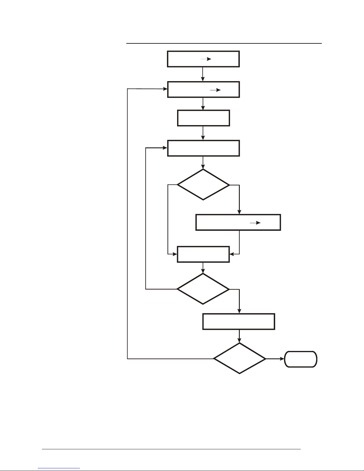
2.4.1 CRC 16 Flow Chart
CRC 16 XOR byte
NO
Hex FFFF
n = 0
Shift to right CRC 16
Carry
CRC 16 XOR Hex A001
CRC 16
CRC 16
YES
CRC 16
n = n + 1
NO
N > 7
NO
YES
Next Byte
End
message
YES
END
9

2.4.2 Visual Basic Calculate CRC16 example
Function CRC16(String As String) As String
Dim N As Integer, i As Integer, NByte As Integer
Dim CRC As Long, a As Byte
Dim Buffer As String
NByte = Len(String)
CRC = 65535
For i = 1 To NByte
a = Asc(Mid$(String, i, 1)) 'C(I)
CRC = (CRC Xor a) And &HFFFF
For N = 0 To 7
If CRC And 1 Then
CRC = (CRC \ 2)
CRC = (CRC Xor 40961)
Else
CRC = CRC \ 2
End If
Next
Next
Buffer = Right$("0000" + Hex$(CRC And &HFFFF), 4)
CRC16 = Chr$("&H" + Right$(Buffer, 2)) + Chr$("&H" + Left$(Buffer, 2))
End Function
2.5 Message Synchronisation
Message synchronisation between the transmitter and the receiver is
obtained by inserting a pause of at least 3.5 times the time of one
character between the messages. If the receiving device does not
receive for the time required for 3 characters, it considers the previous
message completed and concludes that the next byte received will be the
first of a new message and, consequently, an address.
3. The MODBUS Functions
3.1 Read Output Status (01)
This section provides a detailed description of the MODBUS functions
implemented on ATHENA CONTROLS instruments.
This function is used for requesting the ON or OFF status of binary
logical variables. Broadcast mode is not allowed.
Question
In addition to the address of the slave and the function code (01), the
message contains the starting address expressed in two bytes and the
number of bits to be read, also occupying two bytes. Address numbering
starts from zero (bit1 = 0) for MODBUS, or one (bit1 = 1) for JBUS.
10

Example: Request for slave 17 to read bits 0004 to 0015.
ADDR FUNC
DATA
start
Addr HI
DATA
start
Addr LO
DATA
bit #
HI
DATA
bit #
LO
CRC
HI
CRC
LO
11 01 00 03 00 0C CE 9F
Answer
In addition to the address of the slave and the function code (01), the
message comprises a character containing the number of data bytes and
the characters containing data. The data are compacted, so one byte
contains the status of 8 bits, the least significant bit of the first byte must
contain the bit corresponding to the starting address and so on. If the
number of bits to be read is not a multiple of 8, the last character must be
completed with zeros in the most significant bits.
Example: Answer to the request indicated above.
ADDR FUNC
DATA
Byte
Count
DATA
bit
04..11
DATA
bit
12..15
CRC
HI
CRC
LO
11 01 02 CD 0B 6D 68
3.2 Read Input Status (02)
This function works in exactly the same way as the previous one.
3.3 Read Output Registers (03)
This function is used for requesting the value of 16-bit (word) registers
containing numeric variables. Broadcast mode is not allowed.
Question
In addition to the address of the slave and the function code (03), the
message contains the starting address expressed in two bytes and the
number of words to be read, also occupying two bytes. The maximum
number of words that may be read is 125. Address numbering starts from
zero (word1 = 0) for MODBUS, or one (word1 = 1) for JBUS.
Example: Request for slave 25 to read registers 069 to 0071.
ADDR FUNC
DATA
start
Addr HI
DATA
start
Addr LO
DATA
word #
HI
DATA
word #
LO
CRC
HI
CRC
LO
19 03 00 44 00 03 46 06
Answer
In addition to the address of the slave and the function code (03), the
message comprises a character containing the number of data bytes and
the characters containing data. The registers require two bytes each, the
first of which contains the most significant byte.
Example: Answer to the request indicated above.
ADDR FUNC
DATA
Byte
Count
DATA
word
69 HI
DATA
word
69 LO
DATA
word
70 HI
DATA
word
70 LO
DATA
word
71 HI
DATA
word
71 LO
CRC
HI
CRC
LO
19 03 06 02 2B 00 00 00 64 AF 7A
3.4 Read Input Registers (04)
This function works in exactly the same way as the previous one.
11

3.5 Force Single Coil (05)
This function is used for forcing the status of a single binary variable ON
or OFF. Broadcast mode is allowed.
Question
In addition to the address of the slave and the function code (05), the
message contains the address of the variable to be forced in two bytes
and two characters of which the first is set to FFh (255) to force it ON and
00h to force it OFF, while the second is always set to zero. Address
numbering starts from zero (bit1 = 0) for MODBUS, from one (bit1 = 1) for
JBUS.
Example: Request to force bit 4 on slave 47 ON.
ADDR FUNC
DATA
bit #
HI
DATA
bit #
LO
DATA
ON/OFF
DATA
(zero)
CRC
HI
CRC
LO
2F 05 00 03 FF 00 7A 74
Answer
The answer consists in retransmitting the message received once the
variable has been changed.
Example: Answer to request mentioned above.
ADDR FUNC
DATA
bit #
HI
DATA
bit #
LO
DATA
ON/OFF
DATA
(zero)
CRC
HI
CRC
LO
2F 05 00 03 FF 00 7A 74
3.6 Preset Single Register (06)
This function is used for setting the value of a single 16-bit register.
Broadcast mode is allowed.
Question
In addition to the slave and the function code (06), the message contains
the address of the variable expressed in two bytes and the value to be
assigned. Address numbering starts from zero (word1 = 0) for MODBUS,
from one (word1 = 1) for JBUS.
Example: Request to force address 26 of slave 38 to 926.
ADDR FUNC
26 06 00 19 03 9E DF 82
Answer
The answer consists in retransmitting the message received once the
variable has been changed.
Example: Answer to request indicated above.
ADDR FUNC
26 06 00 19 03 9E DF 82
DATA
bit #
HI
DATA
bit #
HI
DATA
bit #
LO
DATA
bit #
LO
DATA
WORD
HI
DATA
WORD
HI
DATA
WORD
LO
DATA
WORD
LO
CRC
HI
CRC
HI
CRC
LO
CRC
LO
12

3.7 Read Status (07)
This function is used for reading the status of eight predetermined bits
with a compacted message. Broadcast mode is not allowed.
Question
The message consists only of the slave address and the function code
(07).
Example: Request of the status of slave 25.
ADDR FUNC CRC
HI
CRC
LO
19 07 4B E2
Answer
In addition to the address of the slave and the function code (07), the
message comprises a character containing the status bits.
Example: Answer to the request indicated above.
ADDR FUNC
DATA
status
byte
CRC
HI
CRC
LO
19 07 6D 63 DA
3.8 Force Multiple Coils (15)
This function is used for forcing the status of each binary variable in a
consecutive block. Broadcast mode is allowed.
Question
In addition to the address of the slave and the function code (15), the
message contains the starting address expressed in two bytes, the
number of bits to be written, the number of bytes containing the data and
the data characters. The data are compacted, so one byte contains the
status of 8 bits, the least significant bit of the first byte must contain the
bit corresponding to the starting address and so on. If the number of bits
to be written is not a multiple of 8, the last character must be completed
with zeros in the most significant bits. Address numbering starts from
zero (bit1 = 0) for MODBUS, from one (bit1 = 1) for JBUS.
Example: Request to force 4 bits starting from address 1 on slave 12. Bits
1 and 4 forced to "1" and the others to "0".
ADDR FUNC
0C 0F 00 00 00 04 01 09 3F 09
Answer
In addition to the address of the slave and the function code (15), the
message contains the starting address and the number of bits written.
Example: Answer to request indicated above.
ADDR FUNC
0C 0F 00 00 00 04 55 15
DATA
start
Addr HI
DATA
Addr HI
start
DATA
start
Addr LO
DATA
Addr LO
start
DATA
bit #
HI
DATA
bit #
HI
DATA
bit #
LO
DATA
bit #
LO
DATA
Byte
Count
CRC
HI
DATA
bit
1..4
CRC
LO
CRC
HI
CRC
LO
13

3.9 Preset Multiple Registers (16)
This function is used for setting the value of a consecutive block of 16-bit
registers. Broadcast mode is allowed. Question.
In addition to the address of the slave and the function code (16), the
message contains the starting address, the number of words to be
written, the number of bytes that contain data and the data characters.
Address numbering starts from zero (word1 = 0) for MODBUS, from one
(word1 = 1) for JBUS.
NOTE: In the ATHENA CONTROLS implementation, this function is
present for compatibility but does not permit more than 8 word to be
assigned.
Example: Request to set 1 word to value 268 at address 35 on slave 17.
ADDR FUNC
11 10 00 22 00 01 02 01 0C 6C 87
Answer
In addition to the address of the slave and the function code (16), the
message contains the starting address and the number of words written.
Example: Answer to the request indicated above.
ADDR FUNC
11 10 00 22 00 01 A3 53
DATA
start
Addr HI
DATA
start
Addr LO
DATA
start
Addr HI
DATA
word #
HI
DATA
start
Addr LO
DATA
word #
LO
DATA
Count
DATA
word #
HI
Byte
DATA
word
35 HI
DATA
word #
LO
DATA
word
35 LO
CRC
HI
CRC
HI
CRC
LO
CRC
LO
4. Error Management
In MODBUS there are two types of errors, handled in different ways:
transmission errors and operating errors. Transmission errors are errors
that change the format of the message, the parity (if used) or the CRC16.
A device that detects errors of this type in the message treats it as invalid
and gives no answer. When the format of the message is correct but the
function requested cannot be executed for some reason, an operating
error has occurred. When it detects this kind of error, the slave device
answers by sending an error message. This message consists of the
address, the code of the function requested, an error code and the CRC.
To indicate that the answer is an error message, the function code is
returned with the most significant bit set to "1".
Example: Request for slave 10 to read bit 1185.
ADDR FUNC
DATA
start
Addr HI
DATA
start
Addr LO
DATA
bit #
HI
DATA
bit #
LO
CRC
HI
CRC
LO
0A 01 04 A1 00 01 AC 63
Answer
The request is for the contents of bit 1185, which is not present on the
slave. The slave answers by sending error code "02" (ILLEGAL DATA
ADDRESS) and returns the function code 81h (129).
14

Example: Error code in response to the request indicated above.
ADDR FUNC
DATA
Except.
Code
CRC
HI
CRC
LO
0A 81 02 B0 53
4.1 Error Codes
Although the MODBUS standard uses 8 error codes, the ATHENA
CONTROLS implementation of the protocol uses only four:
Code Name Meaning
01
02
ILLEGAL FUNCTION
ILLEGAL DATA
ADDRESS
03
07
ILLEGAL DATA VALUE
NAK - NEGATIVE
ACKNOWLEDGMENT
The function code received does not correspond
to a function allowed on the addressed slave.
The address to which the data field refers is not
an address allowed on the addressed slave.
The value to be assigned, specified in the data
field, is not allowed for this address.
The function cannot be performed under the
current operating conditions or an attempt has
been made to write in a read-only address.
5. MODBUS ON ATHENA CONTROLS PLATINUM® INSTRUMENTS
5.1 Serial communications parameters
The parameters are shown in the below table:
Parameter Parameter
code
Communications protocol
Serial address
Baud rate
Prot MbuS / JbuS
Addr 1 ... 247
baudr 1200, 2400, 4800, 9600, 19200
The protocol is chosen by means the M.buS o JbuS selection.
The address can be set among 1..247 and must be unique for each
instrument connected on the same line.
The Baud rate parameter enable a clear and simple communications
speed setting.
No Parity and stop bit must be set. They have already been set by the
manufacturer as follows:
Parity = none
Stop bit = 1
5.2 Communications time
The messages, as described in Chapter 2.4, must be exchanged with an
internal pause that is less than 3 times the time required for a character
to be exchanged, otherwise it would be interpreted as the end of the
message. The ATHENA CONTROLS instruments with the MODBUS
protocol are able to receive and transmit characters without an interval.
Between a master message and the following reply on the part of the
instrument there is a latent time lapse necessary for the completion of the
function. This is connected to the fact that, once a command has been
received, the instrument responds only after having completed the
Set up range
15

requested function. To evaluate the lapse in time for different functions
≅
+
≅++
reference can be made to the following expressions:
Request:
where:
T
= Elapsed time.
L
T
= Time of a character.
C
T
= Variable time from 0 to 10mS which is dependent on the internal
S
processes.
Assignment:
where:
T
= Elapsed time.
L
T
= Time of a character.
C
T
= Variable time from 0 to 10mS which is dependent on the internal
S
processes.
T
= Multiple time of 25mS which is dependent on the number of bytes
W
to be written. For assignment of words, this time can be 0, 25 or 50 ms
depending on whether both one or none of the two bytes is equal to
the preceding value; for the assignment of bit T
0 to 100mS.
5.3 Data Base
The ATHENA CONTROLS instrument variables available for serial
communication through the MODBUS protocol are contained in two
distinct sections: the bit zone and the word zone.
5.4 Bit Zone
The bit zone is made up of 16 addressable bits that contain information
on the functioning status of the instruments. With some instruments,
certain bits are not used; the status request for these bits with the 01 and
02 functions is permitted but returns a fixed value of 0; these bits are
indicated in the tables by the presence of a hyphen "-". The assignment
of the bit status with the 05 and 15 functions is only allowed on
addresses in which this is possible, which condition is indicated by "R/W".
5.5 Word Zone
The word zone is made up of 128 addressable words that contain control
variables and the instrument parameters. With some instruments certain
words are not used; the request for the values of these words with the 03
and 04 functions is permitted but returns a fixed value of 0; these words
are indicated in the table by the presence of a hyphen "-". The
assignment of the word value with the 06 and 16 functions is only allowed
on addresses in which this is possible, which condition is indicated by
"R/W". The variables and parameters are coded as integer numbers with
a plus or minus sign (two's complement) without taking into account the
decimal point in the representation (for example: the Proportional Band
displayed on the screen with a decimal digit "25.0" is transmitted as 250).
Assignment is only allowed within the values assigned to each
parameter, any attempt to assign a value outside of those permitted
within the field, will cause the instrument to respond with an error
message and a an exception code equal to 3, and the assignment will not
be carried out.
T3TT
Lcs
T3TTT
Lcsw
it can be a value from
w,
16

5.6 Assignment of the parameters and E2PROM
All the parameters modified from keyboard or assigned through serial
communication, come written in a permanent way in the EEPROM of the
instruments. Like known good, these components have limited writing
cycles beyond to which the component could be damaged. In our case
the number of cycles of writing are about 10.000 and also if this number
could appear limited, we must be held present that the writings during the
arc of life of the instrument don't arrive to overcome the thousand of
cycles. Different thing is when we talk about the serial communication. In
fact the computer could assign any parameter and with any frequency to
the regulators.
Being well aware of this fact, Athena Controls has provided to protect the
component in matter according to different hardware formality and
resources of the instruments. One of the protection made consists of the
fact to compare the new given with the datum already resident. If the two
data correspond, no writing doesn't happen in as not necessary and the
new given comes writing only and entirely if the two data disagree
between them.
Normally the datum that has a frequency of better writing it is the value of
Setpoint. In the instruments C10, M10 and M300 in as not furnished of
NOVRAM or buffered RAM, exists two formality of assignment of the
Setpoint that is:
1) Assignment to the Jbus address 2
2) Assignment to the Jbus address 5
With the first formality, the Setpoint could be assigned endless times
because it work in the RAM of the microprocessor but attention because
at the turning off of the regulator this datum comes lost for engage the
last value that had stayed written locally from keyboard or from the serial
to the Jbus address 5.
With the second formality the datum comes written in a permanent way
directly in the EEPROM of the instrument and the writing must be limited
to a real necessity.
The instruments of the series M5000, X100, X400, X5000 and X7000
possessing a different hardware structure, furnished that is of NOVRAM
or buffered RAM, they are not subdued to the limits previously exposed
and the assignments of the Setpoint to the Jbus addresses 2 or 5 don't
involve any difference. The two addresses come maintained active only
for a problem of compatibility with the preceding series.
6. Electrical Connections
6.1 General Description
All the Platinum® controllers may be fitted with a two wire (half duplex)
RS485 serial comm.s option. It makes the wiring simpler and enables a
larger connection length (maximum 1200 m).
The Platinum ® C10, M10, M300 and M400 instruments do not have any
line termination or polarisation system. If necessary a termination
resistance (120Ω ¼ W) must be connected to the terminals of the last
instrument of the line. In any case the polarisation is not possible.
The Platinum ® M5000, X100, X400 and X5000 instruments do have any
line termination or polarisation system. Please refere to the specific
chapter on these instruments.
17

6.2 Communication Cable Laying Recommendations
In order to minimise interference caused by the external environment to
serial communication, and thus obtain maximum efficiency between the
supervisor and the instruments, a few essential technical precautions
must be taken.
The most important and easiest to implement of all is to separate the
power or power supply lines from the communication lines and lay them
as far as possible from remote-controlled switches, electromagnets,
powerful motors, etc. The same rule applies to the control panel in that it
is pointless to cable the control panel perfectly and then haphazardly
"throw" the cables into the channel or vice versa. If the communication
cables are extended to another control panel or other equipment, leave a
space in the terminal board, isolated from all the other cables (normally
towards the sides).
The type of cable used is of fundamental importance for the functioning of
the entire system. The most important condition to be respected is the
cable's capacity per meter (pF/m). The lower the capacity of the cable is
the longer the line can be. Consequently, power cables, shielded coaxial
cables and general channel cables are to be avoided under all
circumstances in that they have an extremely high capacity per metre. In
addition, to ensure high interference rejection, the cables must be twisted
and preferably provided with a metal shield to be connected to an
efficient ground socket (on one side only).
Two examples of cables with suitable characteristics produced by Belden
are indicated below:
A) Belden code 9729 Z = 100 Ω pF/m = 41
B) Belden code 9502 Z = 150 Ω pF/m = 98
6.3 Instruments with an RS-485 interface (2 wire)
The line requires twisted cable with a characteristic impedance of about
120 Ω.
Normally this type of connection uses a standard 4-wire communication
interface. The transmission and reception signals for the computer and
the communicating device (Tx+Rx+ and Tx-Rx-) can be paralleled,
resulting in a single duplex connection RTx+ and RTx-.
The communication port cannot usually work if it is connected in this way
as every time the supervisor is transmitting a message, it is also present
on the receiving port before awaiting the reply from the other devices. To
prevent this problem occurring, the supervisor uses the RTS (Request To
Send) signal from the communication port. Before beginning a
transmission, the supervisor “raises” the status of its RTS signal to inhibit
its receiver. When the transmission has ended, the supervisor brings the
RTS signal back to “zero” to re-enable its receiver. In the same way, the
devices connected to the supervisor must be able to manage the
direction of the message that is flowing, otherwise the communication will
fail. ATHENA CONTROLS controllers include this ability in their software.
There are commercially available interfaces for handling the RTS signal
at the hardware level, so that it is completely transparent and not
required by the communications software.
It is strongly recommended that the two ends of the link between the
various devices is correctly terminated, as shown in the following drawing
to demonstrate the principle.
18
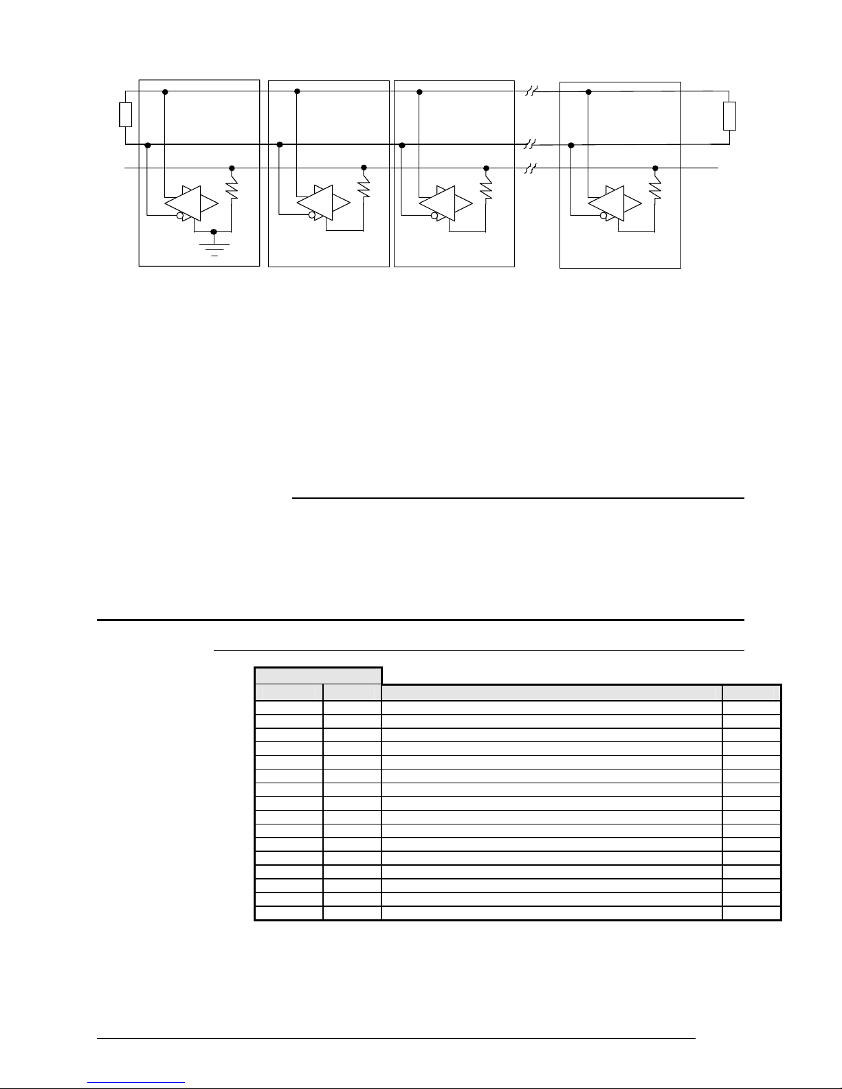
Rt
Supervisor
Rg
G/R
Device 1 Device 2 Device "n"
G/R
Rg
G/R
Rg
G/R
Rt
Co mmon
Rg
G = Transmitter
R = Receiver
G/R = Bi-directional (Receiver/Transmitter) buffer
Rt = Termination resistance: the transmitter can drives up to 32
receivers plus two 120 Ω resistors.
Rg = 100 Ω Resistor
From the above drawing it may be seen that a “star” connection is not
valid. Each branch would have to be terminated, which in turn would
reduce the overall the impedance of the line. In these conditions, the
signal level would be too low for reliable communications.
6.3.1 References
GOULD Gould Modbus Protocol Reference Guide
(PI-MBUS-300 Rev. B)
APRIL JbuS Specification
GLOBAL ENG. DOC. EIA STANDARD RS -485
7. C10 / M10 Controllers
7.1 Bit Zone
Address
Modbus JbuS Variable Type
0 1 - 1 2 - 2 3 - 3 4 Main output condition (0 = OFF, 1 = ON) R
4 5 AL2 alarm status (0 = OFF, 1 = ON) R
5 6 AL3 alarm status (0 = OFF, 1 = ON) R
6 7 Out of range (0 = Normal operation, 1 = Safety) R
7 8 Auto-Tune (0 = OFF, 1 = Run) R
8 9 - -
9 10 Out of range (0 = Normal operation, 1 = Safety) R
10 11 - 11 12 - 12 13 - 13 14 - 14 15 - 15 16 - -
19

7.2 Read Status
Function 07 (Read Status) returns an eight bit status with the following
meanings:
Bit Address Variable
1 (LSB) 1 -
2 2 3 3 4 4 Main output condition (0 = OFF, 1 = ON)
5 5 AL2 alarm status (0 = OFF, 1 = ON)
6 6 AL3 alarm status (0 = OFF, 1 = ON)
7 7 Out of range (0 = Normal operation, 1 = Safety)
8 (MSB) 8 Auto-Tune (0 = OFF, 1 = Run)
7.3 Word Zone - Page 1 Parameters
Address
Modbus JbuS Variable Parameter
Code
0 1 Process variable R
1 2 Setpoint R/W 1
2 3 Main output R
3 4 Target Setpoint R
4 5 Local Setpoint R/W 2
5 6 Proportional Band (Hysteresis ON - OFF) 3
6 7 Overshoot control
7 8 Integral time
8 9 Derivative time
9 10 Output cycling time
10 11 Low range
11 12 High range
12 13 AL2 Alarm threshold
13 14 AL3 Alarm threshold
14 15 AL2 Alarm Hysteresis
15 16 AL3 Alarm Hysteresis
16 .. 28 17 .. 29 - - -
29 30 Setpoint low limit
30 31 Setpoint high limit
31 32 - - 32 33 Main output high limit
33 34 - - 34 35 Setpoint ramp up
35 36 Setpoint ramp down
36 37 Input filter
37 38 Input shift
38 39 Auto-Tune enable
39 40 - - 40 41 Serial comm.s address
41 42 - - 42 43 Retransmission low range
43 44 Retransmission high range
44 .. 99 45 .. 100 - - -
P.b. (hy))
O.C.
t.i.
t.d.
t.c.
Sc.Lo
Sc.Hi
A2S.P
A3S.P
A2hy
A3hy
S.P. L
S.P. H
OP. H
Sl. u
Sl. d
t.FiL
In.Sh
tune
Addr
rt.Lo
rt.Hi
Type
R/W
R/W
R/W
R/W
R/W
R
R
R/W
R/W
R/W
R/W
R/W
R/W
R/W
R/W
R/W
R/W
R/W
R/W
R/W
R/W
R/W
20

7.4 Word Zone - Page 2 Configuration
Address
Modbus JbuS Variable Parameter
100 101 - - 101 102 Configuration code
102 103 AL3 alarm configuration code
103 104 Engineering units
104 105 Decimal point
105 106 Low range for engineering units
106 107 High range for engineering units
107 108 Communications protocol
108 109 Baud rate
109 110 Retransmitted range
110 111 - - 111 112 - - 112 113 Password
113 114 RTX low range calibration value (Reserved)
114 115 RTX high range calibration value (Reserved)
115..119 116..120 - - 120 121 Factory code R(W) 5
121 122 Product code (“C1”) R 6
122 123 - - R
123 124 Software release R 6
124 125 - - R
125 126 Custom code R
126 127 - - 127 128 - - -
Notes:
1. Assignment of Setpoint to the address JbuS 2 writes the Computer
Setpoint. It is different from the Local Setpoint, which can be in any case
set by keypad.
Code
ConF
Con.2
unit
Sc.d.d
Sc.Lo
Sc.Hi
Prot
baud
retr
Code
CAL.3
CAL.4
Type
R/W 4
R/W 4
R/W
R/W 4
R/W 4
R/W 4
R/W 8
R/W 9
R/W
R/W
R/W
R/W
4/7
10
2. Assignment of Setpoint to the address JbuS 5 writes the Local Setpoint
(the previous value is lost).
3. In case of ON - OFF output (address JbuS 6) the proportional band is
substituted by the output Hysteresis.
4. All the configuration parameters are accepted, if valid, but not brought
into effect. To execute the reconfiguration procedure and bring the
changes into effect, the code 55AAh must be written at the address JbuS
121.
5. Address JbuS 121 is read only, but if the code 55AAh (21930d) is written
at this address, the configuration is brought into effect.
6. The JbuS 122 + 123 and 124 + 125 addresses contain the strings (of 4
characters) for the product and release codes: each address represents
two characters, the most significant byte in the word contains the ASCII
code of the second.
7. To select the engineering unit, the value between 0 and 10 must be
assigned as per the below table:
Engineering unit Serial value
°C
°F
0
1
21

none
nU
U
nA
A
bar
PSI
rh
Ph
2
3
4
5
6
7
8
9
10
8. To select the protocol type, the value between 0 and 1 must be
assigned as per the below table:
Protocol type Serial value
Modbus 0
JbuS 1
9. To select the serial comm.s baud rate, the value between 0 and 3 must
be assigned as per the below table:
Baud Rate Serial value
1200 0
2400 1
4800 2
9600 3
10. To select the retransmission signal type, the value between 0 and 1
must be assigned as per the below table:
Retransm. signal type Serial value
0 .. 20 mA 0
4 .. 20 mA 1
7.5 Termination and Polarisation
The Platinum ® C10 and M10 instruments do not have any line
termination or polarisation system. If necessary a termination resistance
(120Ω ¼ W) must be connected to the terminals of the last instrument of
the line. In any case the polarisation is not possible.
8. M300 Controller
8.1 Bit zone
Modbus JbuS Variable Type
10 11 Keypad lock (0 = locked, 1 = unlocked) R/W
Address
0 1 Timer function status (0 = OFF, 1 = Run) 1 R/W
1 2 - 2 3 - 3 4 Main output condition (0 = OFF, 1 = ON) R
4 5 Alarm condition AL2 (0 = OFF, 1 = ON) R
5 6 Alarm condition AL3 (0 = OFF, 1 = ON) R
6 7 Out of range (0 = Normal operation, 1 = Safety) R
7 8 Auto-Tune (0 = OFF, 1 = Run) R
8 9 - 9 10 Out of range (0 = Normal operation, 1 = Safety) R
22

11 12 Outputs lock (0 = locked, 1 = unlocked) R/W
12 13 - 13 14 - 14 15 - 15 16 - -
8.2 Read Status
Function 07 (Read Status) returns an eight bit status with the following
meanings:
Bit Address Variable
1 (LSB) 1 Timer function status (0 = OFF, 1 = Run) 1
2 2 3 3 4 4 Main output condition (0 = OFF, 1 = ON)
5 5 Alarm condition AL2 (0 = OFF, 1 = ON)
6 6 Alarm condition AL3 (0 = OFF, 1 = ON)
7 7 Out of range (0 = Normal operation, 1 = Safety)
8 (MSB) 8 Auto-Tune (0 = OFF, 1 = Run)
Notes:
1. Only available with Timer option.
8.3 Word Zone - Page 1 Parameters
Address
Modbus JbuS Variable Parameter
0 1 Process variable R
1 2 Setpoint R/W 1
2 3 Main output R 2
3 4 Target Setpoint R/W 1
4 5 Local Setpoint R/W 3
5 6 Proportional Band (Hysteresis ON - OFF) 4
6 7 Overshoot control
7 8 Integral time
8 9 Derivative time
9 10 Cycle time
10 11 Low range
11 12 High range
12 13 AL2 Alarm threshold
13 14 AL3 Alarm threshold
14 15 AL2 Alarm Hysteresis
15 16 AL3 Alarm Hysteresis
16 17 Heat/cool proportional band
17 18 Heat/cool integral time
18 19 Heat/cool derivative time
19 20 Heat/cool dead band
20 21 Cool output cycling time
21 22 Cool output high limit
22 23 Motor travel time
23 24 Minimum output step
24 25 Timer setting
25 26 Stand-by Setpoint
26 27 Stand-by Setpoint of Timer
27 28 Soft-start output value
28 29 - - -
Code
P.b. (hy.)
O.C.
t.i.
t.d.
t.c.
Sc.Lo
Sc.Hi
A2S.P
A3S.P
A2hy
A2hy
P.b. C
t.i. C
t.d. C
d.bnd
t.c. C
OP.HC
MU.tM
MU.Hy
tiMe
S.P 2
tM.S.P
St.OP
Type
R/W
R/W
R/W
R/W
R/W
R
R
R/W
R/W
R/W
R/W
R/W
R/W
R/W
R/W
R/W
R/W
R/W
R/W
R/W
R/W
R/W
R/W
23

29 30 Setpoint low limit
30 31 Setpoint high limit
31 32 Error dead band
32 33 Main output high limit
33 34 Output safety value
34 35 Setpoint ramp up
35 36 Setpoint ramp down
36 37 Input filter
37 38 Input shift
38 39 Auto-Tune enable
39 40 - - 40 41 Serial comm.s address
41 42 - - 42 43 Retransmission low range
43 44 Retransmission high range
44 45 start-up Setpoint
45 46 Start Up Holding time
46 47 start-up output high limit
47 48 Timer remaining time
48 49 Load current (CT option)
49 .. 99 50 .. 100 - - -
S.P. L
S.P. H
d.Err
OP. H
Sa.OP
Sl. u
Sl. d
t.FiL
In.Sh
tune
Addr
rt.Lo
rt.Hi
S.P.S.U
t.h.S.U
OP.HS
tM.r.
t.Cur
R/W
R/W
R/W
R/W
R/W
R/W
R/W
R/W
R/W
R/W
R/W
R/W
R/W
R/W
R/W
R/W
R/W
R
8.4 Word Zone - Page 2 Configuration
Address
Modbus JbuS Variable Param. Code Type
100 101 - - 101 102 Configuration code
102 103 AL3 alarm configuration code
103 104 Engineering units
104 105 Decimal point
105 106 Low range for engineering units
106 107 High range for engineering units
107 108 Communication protocol
108 109 Baud rate
109 110 Retransmission range
110 111 Retransmission signal selection
111 112 Current transformer range
112 113 Password
113 114 RTX low range calibration value (Reserved)
114 115 RTX high range calibration value (Reserved)
115 116 Timer/Start-up operating mode
116 117 Timer action
117..119 118..120 - 120 121 Factory code R(W) 6
121 122 Product code ( “M3”) R 7
122 123 - 123 124 Software release R 7
124 125 - 125 126 Custom code R
126 127 - - 127 128 - - -
ConF
Con.2
unit
Sc.d.d
Sc.Lo
Sc.Hi
Prot
baud
retr
rtH
Ht.F.S
Code
CAL.3
CAL.4
t.Mod
t.Act
R/W 5
R/W 5
R/W
R/W 5
R/W 5
R/W 5
R/W 9
R/W
R/W
R/W
R/W
R/W
R/W
R/W
R/W
R/W
24
5/8
10
11
12
13
14

Notes:
1. Assignment of Setpoint to the addresses JbuS 2 and 4 writes the
Computer Setpoint. It is different from the Local Setpoint, which can
be in any case set by keypad.
2. Assignment of output at the address JbuS 3 is only possible if the
Auto/Man option if fitted and when the controller is in Manual mode.
3. Assignment of Setpoint to the address JbuS 5 writes the Local
Setpoint (the previous value is lost).
4. In case of ON - OFF output (address JbuS 6) the proportional band
is substituted by the output Hysteresis.
5. All the configuration parameters are accepted, if valid, but not
brought into effect. To execute the reconfiguration procedure and
bring the changes into effect, the code 55AAh must be written at the
address JbuS 121.
6. Address JbuS 121 is read only, but if the code 55AAh (21930d) is
written at this address, the configuration is brought into effect.
7. The JbuS 122 + 123 and 124 + 125 addresses contain the strings (of
4 characters) for the product and release codes: each address
represents two characters, the most significant byte in the word
contains the ASCII code of the second.
8. To select the engineering unit, the value between 0 and 10 must be
assigned as per the below table:
Engineering unit Serial value
°C
°F
none
nU
U
nA
A
bar
PSI
rh
Ph
9. To select the protocol type, the value between 0 and 1 must be
assigned as per the below table:
Protocol type Serial value
Modbus 0
JbuS 1
10. To select the serial comm.s baud rate, the value between 0 and 3
must be assigned as per the below table:
Baud Rate Serial value
1200 0
2400 1
4800 2
9600 3
0
1
2
3
4
5
6
7
8
9
10
25

11. To select the retransm. output range, the value between 0 and 1
must be assigned as per the below table:
Variable Serial value
0 .. 20 mA 0
4 .. 20 mA 1
12. To select the retransmitted variable (PV or SP), a value between 0
and 1 must be assigned as per the below table:
Variable Serial value
PV 0
SP 1
13. To select the Timer/Start-up operating mode, a value between 0 and
7 must be assigned as per the below table:
Timer/Start-up operating mode Serial
value
Disabled 0
Start-up 1
Counting inside band 2
Counting inside band / End mode OFF 3
Counting when launched 4
Counting when launched / End mode OFF 5
Counting disable when launched 6
Stand-by Setpoint 7
14. To select the Timer action, a value between 0 and 7 must be
assigned as per the below table:
Timer action Serial value
Launch OP3 status Time
By Keypad OFF Second 0
By Keypad ON Second 1
Key +
at power on
Key +
at power on
By Keypad OFF Minute 4
By Keypad ON Minute 5
Key +
at power on
Key +
at power on
OFF Second 2
ON Second 3
OFF Minute 6
ON Minute 7
8.5 Termination and Polarisation
The Platinum ® M300 instruments do not have any line termination or
polarisation system. If necessary a termination resistance (120Ω ¼ W)
must be connected to the terminals of the last instrument of the line.
In any case the polarisation is not possible.
26

9. M400 Controller
9.1 Bit zone
9.2 Read Status
9.3 Word zone - Page 1 Parameters
Address
Modbus JbuS Variable Type
0 1 Timer function status (0 = OFF, 1 = Run) 1 R/W
1 2 Auto/Man (0 = Auto, 1 = Man) 2 R/W
2 3 - 3 4 Control output status (0 = OFF, 1 = ON) R
4 5 AL2 alarm status ( 0 = OFF, 1 = ON ) R
5 6 AL3 alarm status ( 0 = OFF, 1 = ON ) R
6 7 Out of range (0 = Normal operation, 1 = Safety) R
7 8 Auto Tuning ( 0=OFF 1=Run ) R
8 9 - -
9 10 Out of range (0 = Normal operation, 1 = Safety) R
10 11 Keypad lock (0 = locked, 1 = unlocked) R/W
11 12 Outputs lock (0 = locked, 1 = unlocked) R/W
12 13 Logic input #1 ( 0=Open 1=Close ) R
13 14 - 14 15 - 15 16 - -
Function 07 (Read Status) returns an eight bit status with the following
meanings:
Bit Address Variable
1 (LSB) 1 Timer function status (0 = OFF, 1 = Run) 1
2 2 Auto/Man (0 = Auto, 1 = Man) 2
3 3 4 4 Control output status (0 = OFF, 1 = ON)
5 5 Alarm 2 ( 0 = OFF, 1 = ON )
6 6 Alarm 3 ( 0 = OFF, 1 = ON )
7 7 Out of range (0 = Normal operation, 1 = Safety)
8 (MSB) 8 Auto Tune ( 0=Disabled 1=Run )
Notes:
1. Only available with Timer option.
2. Only available with Auto/Man function.
Address
Modbus JbuS Variable Parameter
Type
Code
0 1 Process variable - R
1 2 Setpoint - R/W 1
2 3 Main output - R(W) 2
3 4 Local Setpoint - R/W 1
4 5 Local Setpoint - R/W 3
5 6 Proportional Band (Hysteresis ON - OFF) 4
6 7 Overshoot Control
7 8 Integral time
8 9 Derivative time
9 10 Cycle time
10 11 Low range
11 12 High range
P.b. (hy.)
O.C.
t.i.
t.d.
t.c.
Sc.Lo
Sc.Hi
R/W
R/W
R/W
R/W
R/W
R
R
27

12 13 AL2 alarm threshold
13 14 AL3 alarm threshold
14 15 AL2 alarm Hysteresis
15 16 AL3 alarm Hysteresis
16 17 Relative Cold Gain
17 18 Cool output Hysteresis (On-OFF only)
18 19 19 20 Heat/Cool dead band
20 21 Cool output cycling time
21 22 Cool output maximum value
22 23 Motor travel time
23 24 Minimum output step
24 25 Timer setting
25 26 Stand-by Setpoint
26 27 Soft start output high limit
27 28 Soft-start activation time
28 29 - - 29 30 Setpoint low limit
30 31 Setpoint high limit
31 32 PID Dead Band
32 33 Main output high limit
33 34 Output safety value
34 35 Setpoint ramp up
35 36 Setpoint ramp down
36 37 Input filter
37 38 Input shift
38 39 Start/Stop One shoot tuning ( 0=Stop 1=Run)
39 40 40 41 Serial comm.s address
41 42 42 43 Retransmission low range
43 44 Retransmission high range
44 45 Start-Up Setpoint
45 46 Start-Up Hold time
46 47 Output high milit during Start-up
47 48 Timer remaining time
48 49 Load current in ampere
49 - 99 50 - 100 - - -
A2S.P
A3S.P
A2hy
A2hy
r.C.Ga
Hy. C
-
d.bnd
t.c. C
OP.HC
MU.tM
MU.Hy
tiMe
tM.S.P
St.OP
St.tM
S.P. L
S.P. H
d.Err
OP. H
Sa.OP
Sl. u
Sl. d
t.FiL
In.Sh
tune
-
Addr
-
rt.Lo
rt.Hi
S.P.S.U
t.h.S.U
OP.HS
tM.r.
t.Cur
R/W
R/W
R/W
R/W
R/W
R/W
R/W
R/W
R/W
R/W
R/W
R/W
R/W
R/W
R/W
R/W
R/W
R/W
R/W
R/W
R/W
R/W
R/W
R/W
R/W
R/W
R/W
R/W
R/W
R/W
R/W
R/W
R
9.4 Word zone - Page 2 Configuration
Address
Modbus JbuS Variable Parameter
Code
100 101 101 102 Configuration code
102 103 AL3 alarm configuration code
103 104 Engineering units
104 105 Decimal point
105 106 Low range for engineering units
106 107 High range for engineering units
-
ConF
Con.2
unit
Sc.d.d
Sc.Lo
Sc.Hi
Type
R/W 5
R/W 5
R/W
R/W 5
R/W 5
R/W 5
5/8
28

107 108 Communications protocol
108 109 Baud rate
109 110 Retransmission range
110 111 Retransmission signal selection
111 112 Current transformer range
112 113 Password
113 114 RTX low range calibration value (Reserved)
114 115 RTX high range calibration value (Reserved)
115 116 Timer operating mode
116 117 Timer action
117 118 Digital input function
118 119 119 120 120 121 Factory code
121 122 Product code (“M4”) 7
122 123 123 124 Software release (p. es. “ 00A”) 7
124 125 125 126 Custom code
126 127 127 128 -
Prot
baud
retr
rtH
Ht.F.S
Code
CAL.3
CAL.4
t.Mod
t.Act
IL.Fn
-
-
-
-
-
R/W 9
10
R/W
11
R/W
12
R/W
R/W
R/W
R/W
R/W
13
R/W
14
R/W
15
R/W
-
-
R(W) 6
R
R
R
-
R
-
-
Notes:
1. Assignment of Setpoint to the addresses JbuS 2 and 4 writes the
Computer Setpoint. It is different from the Local Setpoint, which can
be in any case set by keypad.
2. Assignment of output at the address JbuS 3 is only possible if the
the Auto/Man option if fitted and when the controller is in Manual
mode.
3. Assignment of Setpoint to the address JbuS 5 writes the Local
Setpoint (the previous value is lost).
4. In case of ON - OFF output (address JbuS 6) the proportional band
is substituted by the output hysteresis.
5. All the configuration parameters are accepted, if valid, but not
brought into effect. To execute the reconfiguration procedure and
bring the changes into effect, the code 55AAh must be written at the
address JbuS 121.
6. Address JbuS 121 is read only, but if the code 55AAh (21930d) is
written at this address, the configuration is brought into effect.
7. The JbuS 122 + 123 and 124 + 125 addresses contain the strings
(of 4 characters) for the product and release codes: each address
represents two characters, the most significant byte in the word
contains the ASCII code of the second.
8. To select the engineering unit, the value between 0 and 10 must be
assigned as per the below table:
Engineering unit Serial value
°C
°F
none
nU
U
nA
0
1
2
3
4
5
29

A
bar
PSI
rh
Ph
9. To select the protocol type, the value between 0 and 1 must be
assigned as per the below table:
Protocol type Serial value
Modbus 0
JbuS 1
10. To select the serial comm.s baud rate, the value between 0 and 3
must be assigned as per the below table:
Baud Rate Serial value
1200 0
2400 1
4800 2
9600 3
11. To select the retransm. output range, the value between 0 and 1
must be assigned as per the below table:
Variable Serial value
0 .. 20 mA 0
4 .. 20 mA 1
12. To select the retransmitted variable, a value between 0 and 3 must
be assigned as per the below table:
Variable Serial value
PV 0
SP 1
MV ( OP Heat ) 2
MVC ( OP Cool ) 3
13. To select the Timer/Start-up operating mode, a value between 0 and 7
must be assigned as per the below table:
Timer/Start-up operating
mode
Disabled 0
Start-up 1
Counting inside band 2
Counting inside band / End
mode OFF
Counting when launched 4
Counting when launched /
End mode OFF
Counting disable when
launched
Stand-by Setpoint 7
6
7
8
9
10
Serial value
3
5
6
30
 Loading...