

Page 1
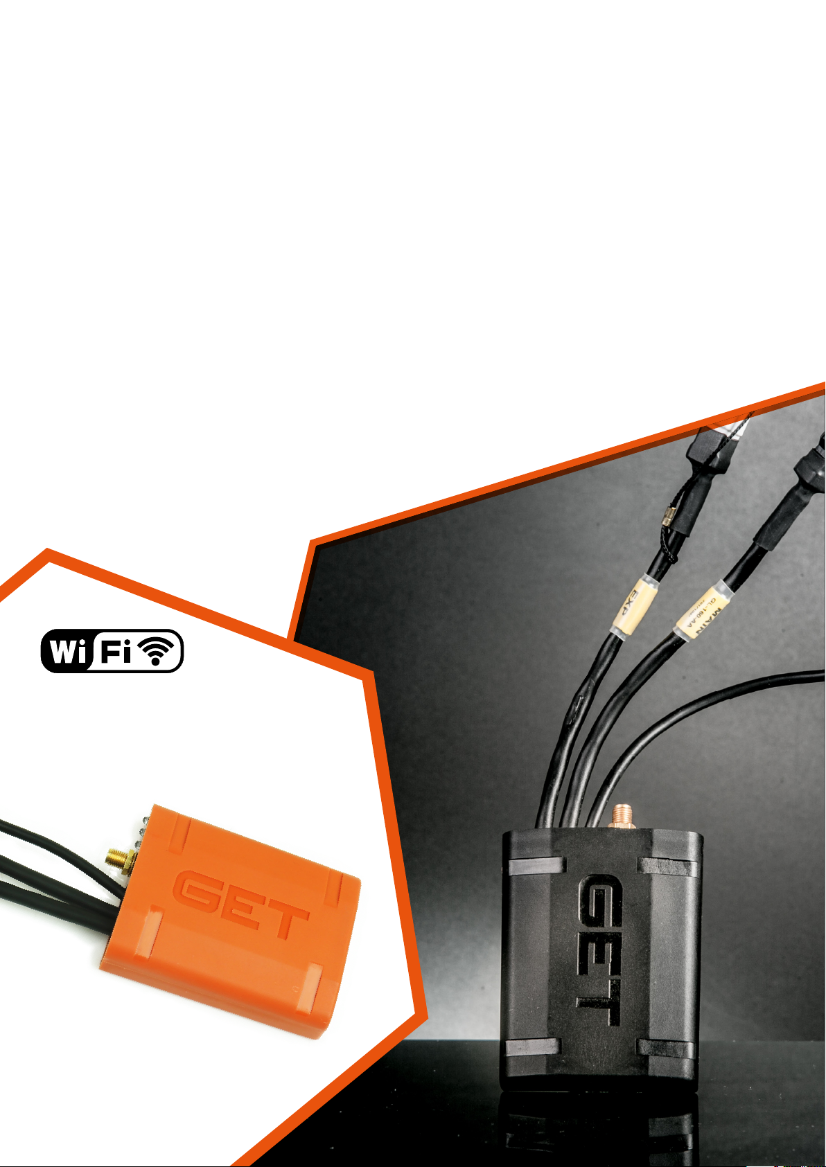
SL1
User Manual
Page 2

ENGLISH
SL1 DATALOGGER User Manual Rev.AA
Dear customer,
thank you for choosing a GET DATA ACQUISITION AND ANALYSIS SYSTEMS by Athena.
We are sure that our passion and exper ience will help you to express successf ully in all competitions,
we ask you to read carefully this user manual. We are confident that this will help you in the use
of you new product GET by Athena.
SL1 Data Logger family , due to GPS technology, can log not only signal from connected sensors
but also data concerning trajectories and vehicle speed.
Data download and configuration of SL1 datalogger are done by LynXLog software.
LynXLog installer includes WinTAX4 Junior analysis software*.
This manual is dedicated to illustrate to the end user information on S L1 datalogger functions.
*WinTAX Junior requires activation code: to get it please contact us.
THIS IS A PRE-SERIES VERSION OF SL1
SOME FEATURES (WHICH ARE PRESENT IN M40 FAMILY) AREN’T IMPLEMENTED YET.
SUCH AS:
• POLYLINE CALIBRATION
• BUILT INERTIAL PLATFORM MANAGEMENT
• CHANNEL REAL TIME VIEW
• AUTOMATIC LAP SPLIT
• TRACK CREATION
PLEASE NOTE: LAST TWO FUNCTIONS CAN BE DONE BY WinTAX4 SOFTWARE.
ANYWAY WE ARE FOCUSED TO SOLVE EVERYTHING AS SOON AS POSSIBLE.
WE RECOMENDED TO EXECUTE LynXLog UPDATES WHEN THEY ARE SUGGESTED.
THANK YOU FOR YOUR COOPERATION
GET Staff
The content of this document, part of this document, could be copied, transferred, send or
memorized on other form without the written consent of GET by Athena.
GET has the right to change without notice the content of this manual.
2
[email protected]www.getdata.it
Page 3
SL1 DATALOGGER User Manual Rev.AA
ENGLISH
INDEX
1 SL1 KIT 4
2 WHY DATA LOGGING 5
3 GPS SYSTEM 5
3.1 GPS antenna installation 6
3.2 GPS fixing 6
4 WHAT DO YOU NEED 7
5 SL1: INSTALLATION 7
5.1 Precautions 8
6 SL1: FRONT VIEW 8
7 LEDs BEHAVIOR 9
8 BEFORE STARTING 10
8.1 Install LynXLog pack (LynXLog + WinTAX Junior version) 10
8.1.1 How to activate WinTAX4 Junior license 15
9 SL1 WORKING DIAGRAMS 15
10 SL1 POWER MANAGEMENT 16
11 LynXLog SOFTWARE INTERFACE 16
11.1 LynXLog NavBar 17
11.2 LynXLog Function buttons 17
11.3 LynXLog Status Bar 18
12 HOW TO 18
12.1 Connect SL1 to a PC 18
12.1.1 USB Connection 18
12.2 Set data archiviation folder 19
12.3 Download recorded data (Run) 20
12.4 Delete recorded data (Run) 21
12.5 Open, save and edit SL1 Data Logging configuration 22
12.5.1 Get Data Logging Configuration from SL1 23
12.5.2 Open saved Data Logging Configuration file (.set) 24
12.5.3 Upload Data Logging Configuration to SL1 25
12.5.4 Edit Data Logging Configuration 26
12.6 Change SL1 hardware settings 27
13 SL1 TECHNICAL CHARACTERISTICS 28
APPENDIX 1 DATA LOGGING CONFIGURATION DETAILS 29
1 SET INFO 30
2 SET TRIGGERS 31
3 AN/FRQ PANEL (PHYSICAL INPUTS: AN1..AN3, IC1) 32
4 CAN Port GET AND CAN Port EXP PANEL 33
4.1 Add new CAN Channel 33
4.2 Edit existing CAN channel 36
5 GPS PANEL 37
APPENDIX 2 PINOUTS 37
1 “MAIN” CONNECTOR 38
2 “EXP” CONNECTOR 38
3 “USB” CONNECTOR 39
APPENDIX 3 WIRING LOOMS FOR SL1 CONNECTION 40
1 MAIN POWER/IC WIRING CODE GL-0178-AA 40
2 EXPANSION WIRING CODE GL-0179-AA 41
3 MULTILINK WIRING CODE GL-0167-AB 42
APPENDIX 4 SL1 CONNECTION DIAGRAMS 43
4 RX1/GP1 ECUS-SL1 (BATTERY LESS CONFIGURATION) 43
NOTE 44
[email protected]www.getdata.it
3
Page 4
ENGLISH
SL1 DATALOGGER User Manual Rev.AA
1 SL1 KIT
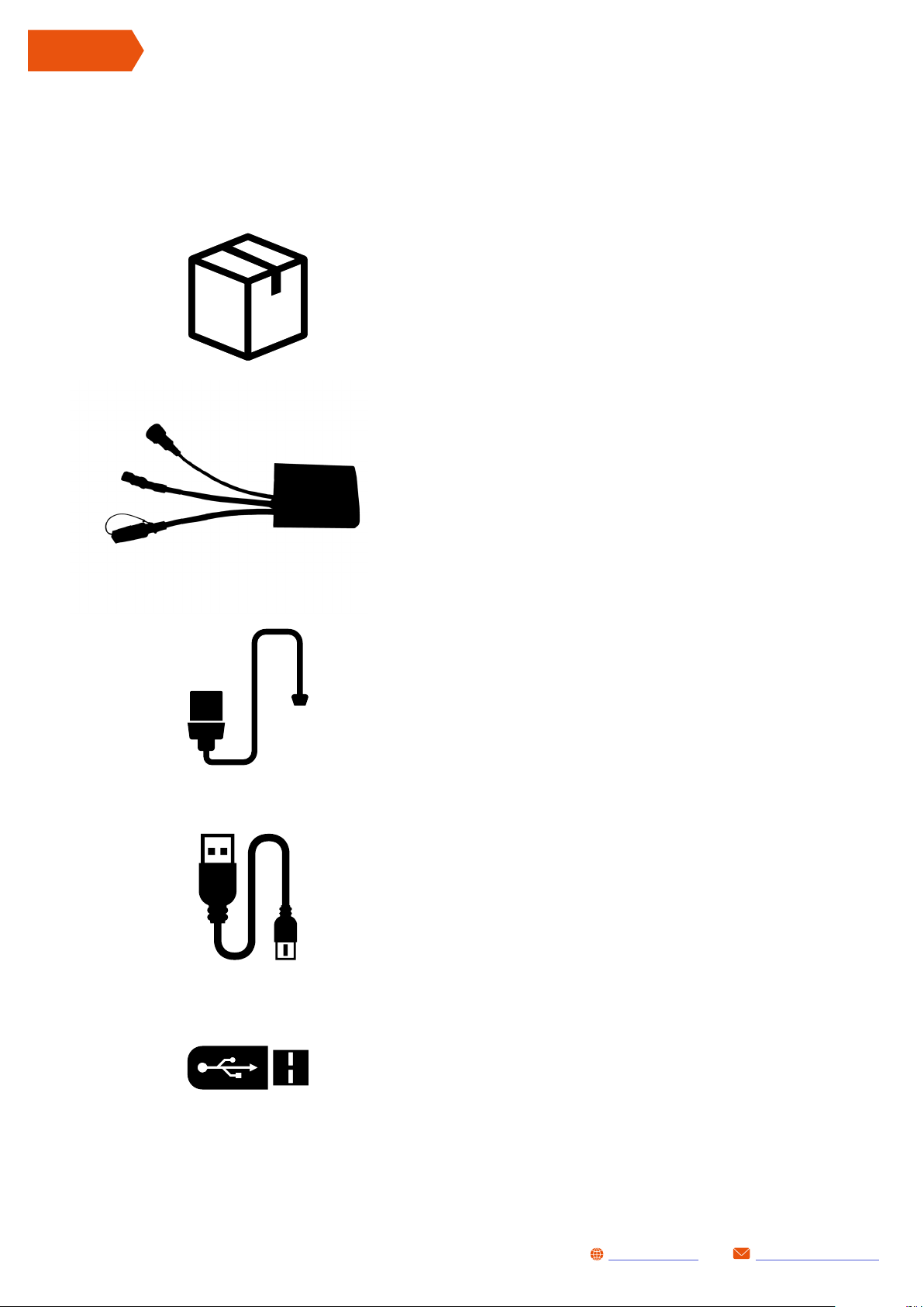
SL1 kit is comprehensive of:
Box
SL1 data logger
1 GPS Antenna
1 data cable (mini - USB cable) for PC connection
1 USB key
PLEASE NOTE: kit content can be different accordingly to the versions.
4
[email protected]www.getdata.it
Page 5

2 WHY DATA LOGGING
Logging data during test sessions or test bench is becoming more and more important because:
• You can reduce setup time on the vehicle
• You can solve driving mistakes
• You can evaluate vehicle behaviour statically and dynamically
• You can visualize all logged parameters
• You can check continuously engine and chassis performances
• You can see lap times once downloaded
SL1 DATALOGGER User Manual Rev.AA
ENGLISH
3 GPS SYSTEM
GPS (Global Positioning System) system, on which your GET system is based, uses a spherical
positioning algorithm in order to identify the position of receiver the signal coming from satellites.
Measuring the time needed by a radio signal to cover the distance satellite-receiver and knowing
the precise position of at least 4 satellites, it is possible to identify the 3D position of the receiver.
24 GPS satellites, arranged in orbits inclined at 55 degrees to the equator, are between 18000
and 20000 km from the Earth and they rotate completely in 12 hours.
Satellites transmit signals of 1.2 and 1.5 GHz (to avoid errors coming from atmosphere refraction)
originated by a single oscillator (atomic clock). Transmitted data contain information on satellite’s
orbit and time signal (messages of Ephemeris) that permit to the receiver to define position on
earth surface.
Time lapping is done via GPS: this solution avoid uncomfortable beacons
side the track and help to have timing references during data analysis.
GPS is a stochastic algorithm and it is strictly linked to the correct signal
receiving. In case of electromagnetic or ambient interferences the quality
of data is not guaranteed.
The minimum received number of satellites in order to guarantee a proper
quality in time lapping is 5.
[email protected]www.getdata.it
5
Page 6

ENGLISH
SL1 DATALOGGER User Manual Rev.AA
3.1 GPS ANTENNA INSTALLATION
In order to install properly the GPS antenna please refer to the following instructions:
• Be really careful during GPS antenna movement: Avoid shocks and verify that connector and
cable are in a perfect shape
• Fix the antenna outside the vehicle: obstacles near to the antenna could cause a reduction to
the receiving capabilities of the sensor. A wrong position could cause an incorrect lap timing,
wrong data acquisition and wrong trajectories
• Do not twist the antenna cable around other cables (especially around high voltage plugs
wiring): this could cause inductive interferences and cause problems during the functioning
• Let pass the antenna cable as far as possible from spark plugs and other electromagnetic
field. In motorbikes it is preferable to run the cable out of the chassis but in any case in a
protected zone
• Fix the GPS connector to the ANTENNA input in MD40 without use excessive torque: do not
use tools
Some suggestions to fix the antenna:
• Speed bikes: fix the antenna in the far back part of the motorbike away from heat sources
(exhaust) or in cockpit area (on top of it).
• Off-road bike: fix the antenna on handlebar handle pad.
• Car: fix the antenna on top of the roof.
• Kart: fix the antenna on the higher part of front number plate, if needed manufacture a support
to address the sensor in the proper direction.
3.2 GPS FIXING
You need to “fix” satellites in order to get trajectories and lap times in analysis software.
The minimum number of satellites to get a correct acquisition is 5.
In fixed application (e.g. dyno sessions) you do not need GPS.
NOTE: SL1 will continue to search satellites during logging. This permit to start the acquisition
also without GPS data. In this case it will be probable that trajectories visualization (done via
software) could be compromise.
The evidence of this phenomena are fast variations on the position of vehicle (spike), up to
some kilometres!!!!
6
[email protected]www.getdata.it
Page 7
4 WHAT DO YOU NEED
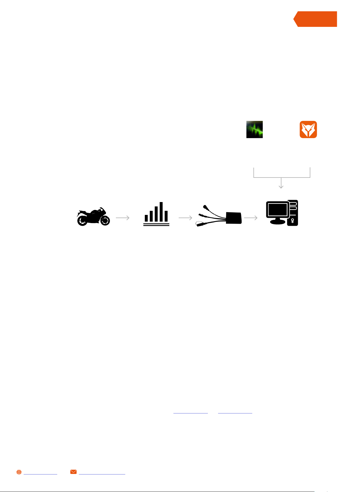
Data logging requires:
• Signals and/or digital data (e.g CAN bus) from vehicle
• SL1 correctly configure to collect desired data
• Personal computer
• LynXLog software (required to download recorded data and to configure SL1 system)
• WinTAX4 software (required for data analysis)
SL1 DATALOGGER User Manual Rev.AA
ENGLISH
WINTAX
Data Analysis
Software
Sensor signals &
data from CAN
BUS
SL1 data loggers could be linked to the vehicle (or sensors) with specific cable
(please refer to Appendix 3).
SL1 data loggerVehicle PC
Logger Manager
LYNXLOG
Software
5 SL1: INSTALLATION
SL1 has been designed to be easily installed in all vehicles.
With dedicated cables it is possible to connect directly to ECU by Athena (example RX1PRO)
via CAN bus.
For electrical connections please read Appendix 2 and Appendix 3 of this manual.
[email protected]www.getdata.it
7
Page 8
ENGLISH
SL1 DATALOGGER User Manual Rev.AA
5.1 PRECAUTIONS
Before proceeding with installation of SL1 onto a vehicle please observe the following rules:
• Work in a user friendly environment (example: enough working space)
• Disconnect battery
• Put all removed vehicle parts in a safe place avoiding to damage them
• Install system when engine is cold: during the installation you could be in contact with hot
parts
• Take care to connectors and wirings (avoid sharp surfaces contact or hot parts)
• Keep washers, bolts and nuts in a safe place during SL1 installation
• During installation avoid that any part installed interfere with driving parts or with the driver
WARNING: WRONG INSTALLATION MAY CAUSE INJURY PEOPLE
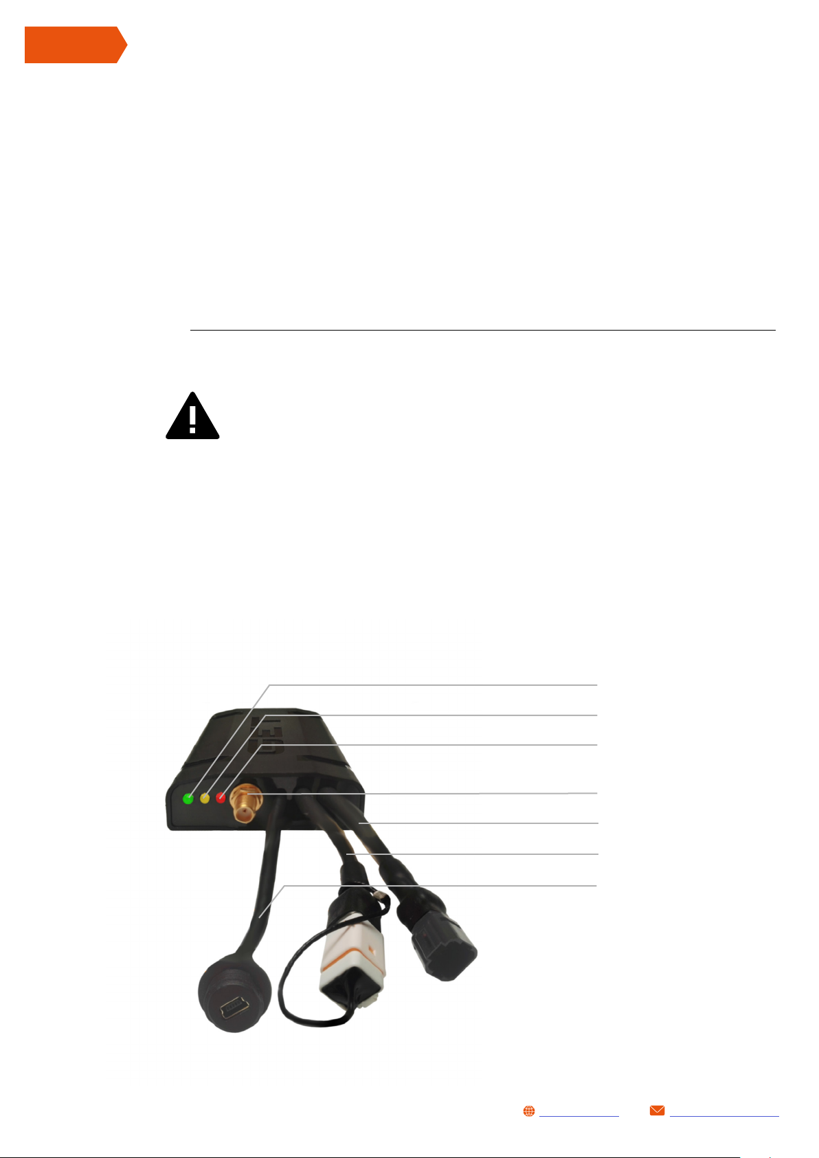
6 SL1: FRONT VIEW
1: STATUS LED - Green
2: GPS LED - Yellow
3: DIAGNOSIS LED - Red
4: GPS Antenna connector
5: Main Connector
6: EXP Connector
7: USB Connector
8
[email protected]www.getdata.it
Page 9
7 LEDs BEHAVIOR
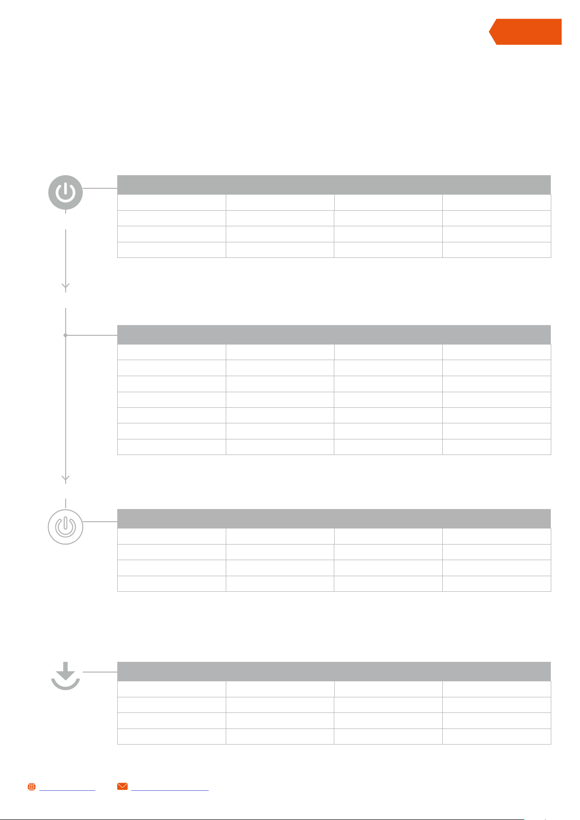
SL1 LED’s gives you information about system status during power up, normal state and switch
off event . See tables below:
POWER UP
LED TYPE STATUS DESCRIPTION
From 5s to 10s
From 20s to 30s
Green GPS BLINK Checking system
Yellow SYSTEM ON Checking system
Red DIAGNOSIS ON Checking system
SL1 DATALOGGER User Manual Rev.AA
ENGLISH
From 3s to 6s
NORMAL CONDITIONS
LED TYPE STATUS DESCRIPTION
Green GPS OFF GPS signal OK
Green GPS BLINK GPS Searching
Yellow SYSTEM ON System Ready
Yellow SYSTEM BLINK Data logging condition
Red DIAGNOSIS OFF System OK
Red DIAGNOSIS BLINK System Alarm
SHUT DOWN
LED TYPE STATUS DESCRIPTION
Green GPS OFF GPS signal OK
Yellow SYSTEM BLINK Data logging condition
Red DIAGNOSIS OFF System OK
OTA Update
SYSTEM UPDATE OTA FUNCTION AND LOGGING CONFIGURATION
LED TYPE STATUS DESCRIPTION
Green GPS ON GPS signal OK
Yellow SYSTEM ON Data logging condition
Red DIAGNOSIS BLINK System OK
[email protected]www.getdata.it
9
Page 10

ENGLISH
SL1 DATALOGGER User Manual Rev.AA
8 BEFORE STARTING
SL1 datalogger requires LynXLog and WinTAX softwares.
Follow instructions below
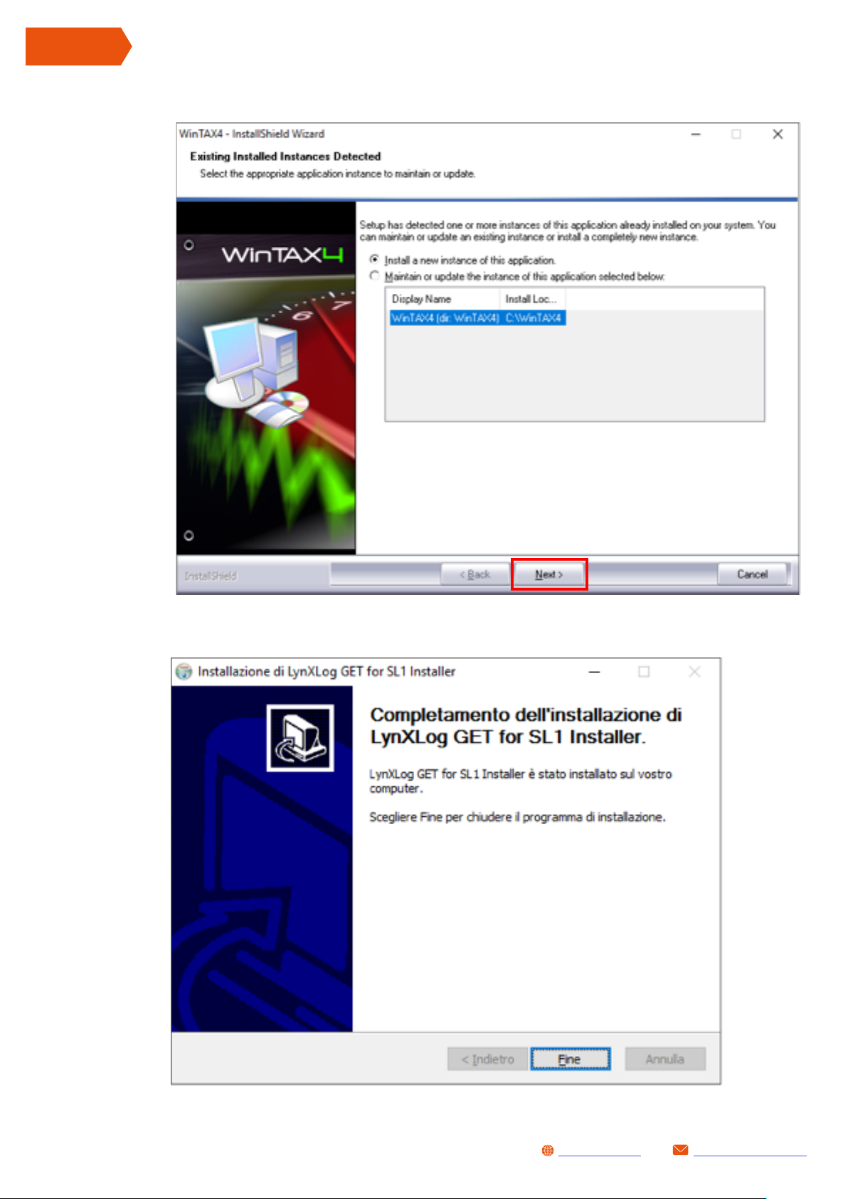
8.1 INSTALL LYNXLOG PACK (LynXLog + WinTAX Junior version)
LynXLog is available for Microsoft Windows©. Official compatible versions are:
Windows© 7 (32 - 64 bit) | Windows© 8 (32 - 64 bit) | Windows© 10 (32 - 64 bit)
To install LynXLog software follow these steps:
Double click on installer software icon:
LynXLog_GET_Install_<Version >.exe
Accept licence terms then click Next>
10
[email protected]www.getdata.it
Page 11
SL1 DATALOGGER User Manual Rev.AA
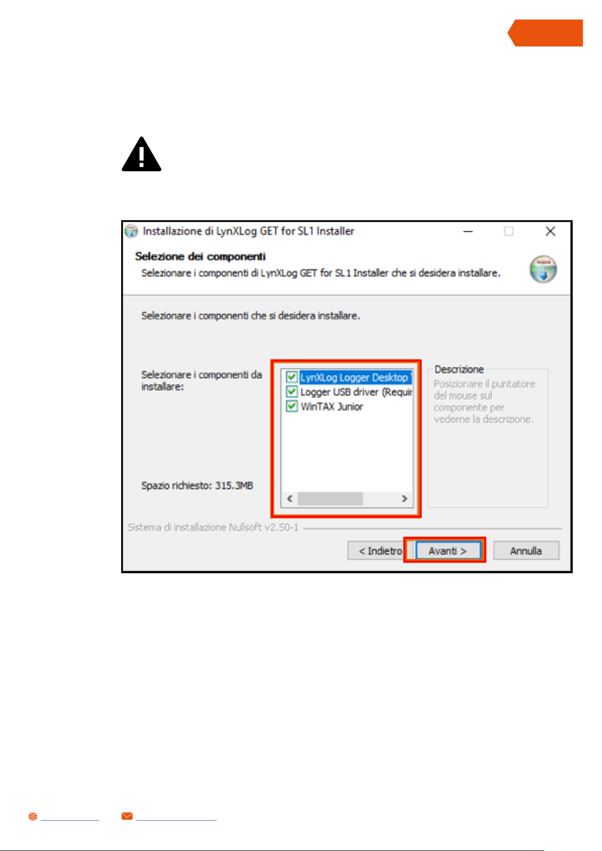
Leave all component checked
(if WinTAX4 User version isn’t installed ) then click Next>
WARNING: leave unchecked WinTAX Junior option if WinTAX4 USER license
is already installed
ENGLISH
[email protected]www.getdata.it
11
Page 12
ENGLISH
SL1 DATALOGGER User Manual Rev.AA
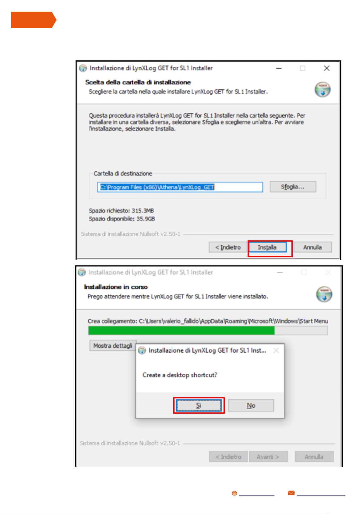
Proceed installation with following window instruction:
1- LynxLog
12
[email protected]www.getdata.it
Page 13

Page 14
Page 15

SL1 DATALOGGER User Manual Rev.AA
8.1.1 HOW TO ACTIVATE WINTAX4 JUNIOR LICENSE
WinTAX4 Junior requires valid license. This is supplied after email request to: [email protected]
E-mail must contains:
WinTAX Registration ID
(displayed when you try to run WinTAX)
GETW Code
(find it inside supplied USB key by opening GETW_code.txt file)
ENGLISH
9 SL1 WORKING DIAGRAMS
First use
LynXLog & WinTAX4
INS TAL LATION
Normal use
WinTAX4 JUNIOR
ACTIVATION
SET DATA
ARCHIVIATION PATH
(Base Directory)
INSTALL LOGGER
ON VEHICLE
CONNECT LOGGER
to pc
CONFIGURE
ACQUISITION
PARAMETERS
CHANNELS,
TRIGGERS,INFO etc.
CONNECT LOGGER
TO PC
[email protected]www.getdata.it
CONFIGURE
ACQUISITION
PARAMETERS IF
NEEDED
DATA LOGGING DOWNLOAD DATA BY
LYNXLOG
DATA ANALYSIS BY
WINTAX
15
Page 16

ENGLISH
SL1 DATALOGGER User Manual Rev.AA
10 SL1 POWER MANAGEMENT
SL1 datalogger can be turned on through MAIN connector or via USB port.
Second options allows data download and logger configuration while system is unpowered (very
useful in battery-less application).
PLEASE NOTE: if system has be powered via USB port auxiliary voltage (5VREF) isn’t available:
this may cause wrong signals on active sensors connected to AN1, AN2 and AN3 inputs.
11 LYNXLOG SOFTWARE INTERFACE
SL1 datalogger requires LynXLog software: it is the interface between datalogger and you which
allows to:
• download and save recorded data to a PC for analysis.
• configure data logging parameters (channels properties, log triggers etc.)
• configure system parameters (e.g. LEDs brightness or GPS dynamics )
See LynXLog starting page in picture below:
LynXLog home page can be divided in three area:
16
LYNXLOG HOME PAGE
AREA FUNCTION
NAVBAR
FUNCTION BUTTONS Give access to LynXLog functions
STATUS BAR Contains system status icons
Useful to move through LynXLog functions without using
FUNCTION BUTTONS
[email protected]www.getdata.it
Page 17

11.1 LYNXLOG NAVBAR
SL1 DATALOGGER User Manual Rev.AA
Click to open LynXLog SYSTEM page
Click to open LynXLog LOG CONFIG page
Click to open LynXLog DATA page
Click to open LynXLog HOME page
ENGLISH
11.2 LYNXLOG FUNCTION BUTTONS
LYNXLOG FUNCTION BUTTONS
BUTTON FUNCTION
DATA
LOG CONFIG
SYSTEM Open SL1 hardware configuration page
[email protected]www.getdata.it
Open Data management page, here you can download, delete and
set archiviation path of logged data
Open Data Logging Configuration page, here you can change channels
properties, log triggers etc.
17
Page 18
ENGLISH
SL1 DATALOGGER User Manual Rev.AA
11.2 LYNXLOG STATUS BAR
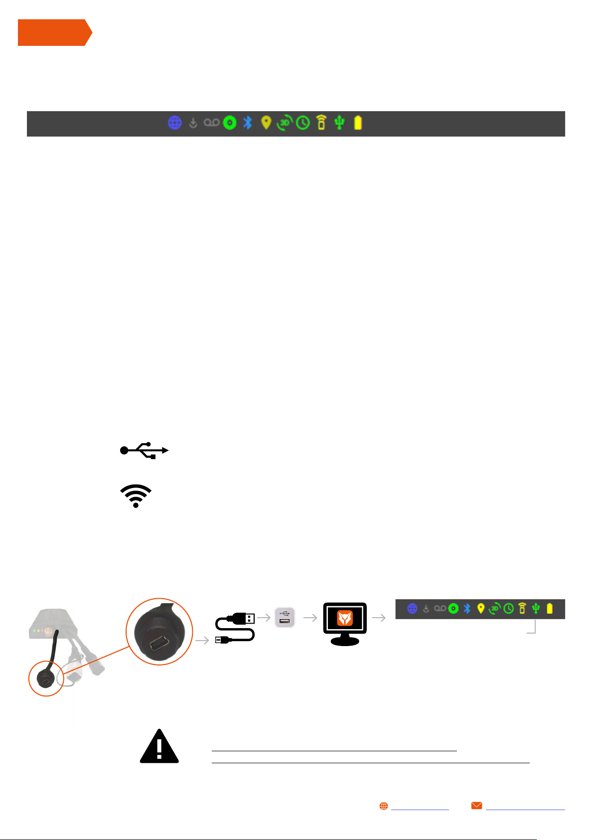
Status bar icons shown status of:
• Internet connection
• System Update (OTA) required
• Internal memory usage
• Bluetooth status
• GPS status
• Inertial measurement unit (IMU) status
• Clock status
• WiFi status
• USB status
• Backup battery status
12 HOW TO
12.1 CONNECT SL1 TO A PC
SL1 datalogger could be connected in two modes:
via USB (cod. GK-SL1-0001 & GK-SL1-0002)
via WiFi (cod. GK-SL1-0001 only)
12.1.1 USB CONNECTION
Follow these steps:
18
Connect SL1 data
cable to logger USB
port.
USB connection ok
Plug the USB into the PC.
PLEASE NOTE:
SL1 DATALOGGERS CAN BE POWERED OVER USB CABLE,
THIS ALLOWS TO DOWNLOAD DATA WITHOUT AUXILIARY POWER SUPPLY
Start LynXLog
software
Wait until LynXLog recognise SL1 device - footer
USB status bar icon becomes green (it may takes
up to 30 second if system is completely off).
[email protected]www.getdata.it
Page 19
SL1 DATALOGGER User Manual Rev.AA
12.2 SET DATA ARCHIVIATION FOLDER
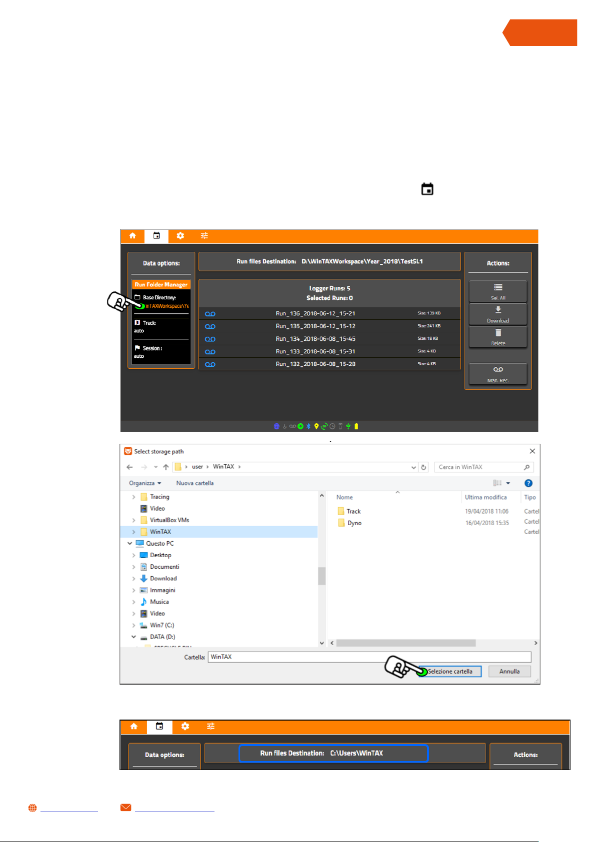
LynXLog soft ware will save all downloaded data (sessions) in a specific folder called Base Directory.
User can change default path (located in ...\Documents\WinTAXWorkspace) by opening DATA page.
Proceed as follow:
• Start LynXLog software
• Open Data page by pressing Data button or click NavBar icon
• Click text below Base Directory field on the left and choose desired archiviation folder:
ENGLISH
• New archiviation folder will be show in Run Field Destination box:
[email protected]www.getdata.it
19
Page 20
ENGLISH
SL1 DATALOGGER User Manual Rev.AA
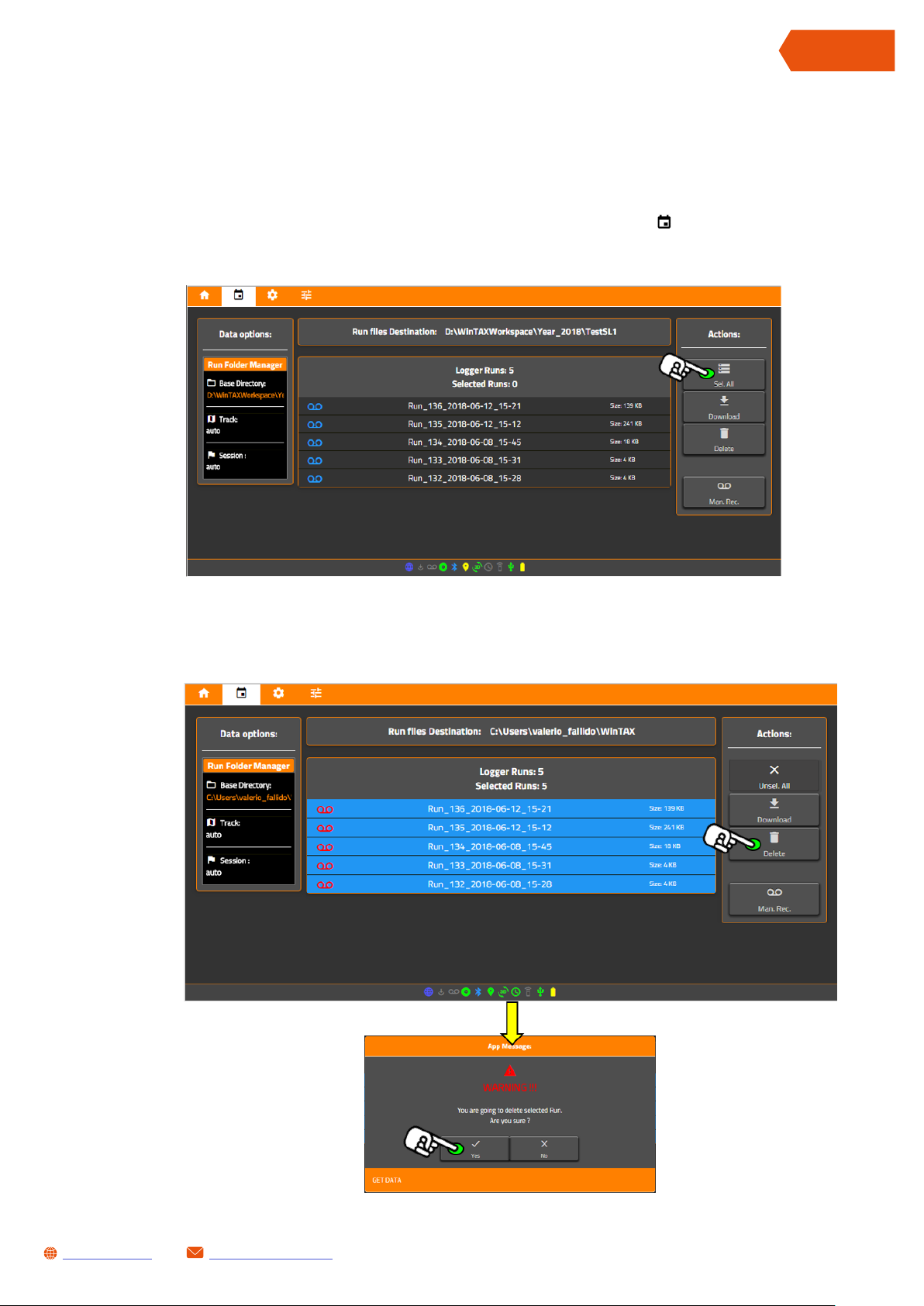
12.3 DOWNLOAD RECORDED DATA RUN
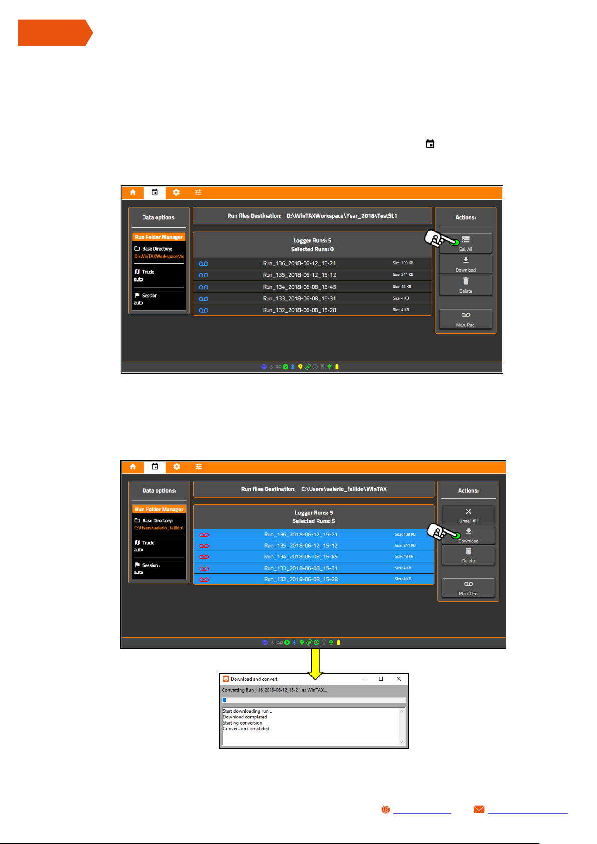
Recorded data can be download from SL1 as follows:
• Connect SL1 to a PC (see chapter 12 .1)
• Open Data page by pressing Data button or click NavBar icon
• Click on a single Run or press Sel. All button to select all data stored in SL1 memory
• Press Download button to start downloading
20
[email protected]www.getdata.it
Page 21
SL1 DATALOGGER User Manual Rev.AA
12.4 DELETE RECORDED DATA RUN
Recorded data can be download from SL1 as follows:
• Connect SL1 to a PC (see chapter 12 .1)
• Open Data page by pressing Data button or click NavBar icon
• Click on a single Run or press Sel. All button to select all data stored in S L1 memory
ENGLISH
• Press Delete button and confirm operation by pressing Yes.
[email protected]www.getdata.it
21
Page 22
ENGLISH
SL1 DATALOGGER User Manual Rev.AA
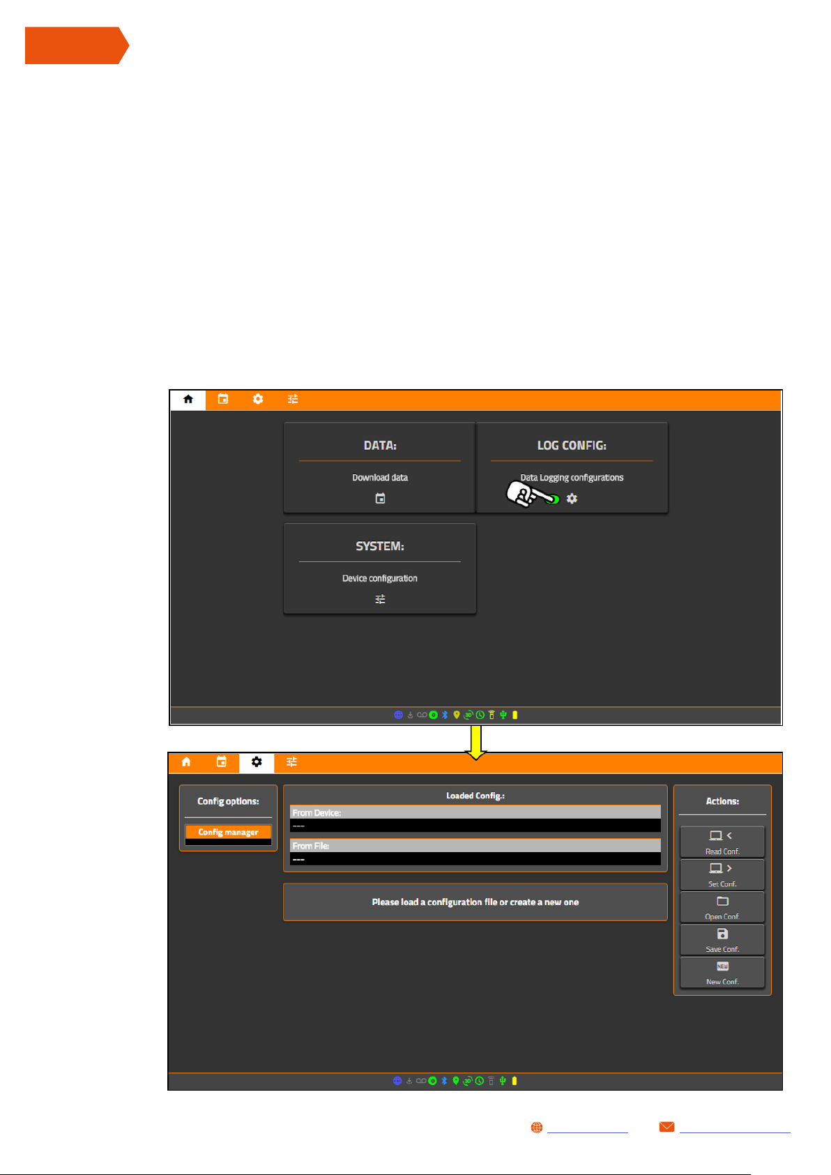
12.5 OPEN, SAVE AND EDIT SL1 DATA LOGGING CONFIGURATION
Data Logging Configuration tells to SL1 how to:
• Set acquisition information (such as vehicle name, driver etc..) useful to identify Runs after
download
• Start data logging
• Which and how acquire a signal (that becomes a channel to log) connected to a physical input
of SL1
All options are available in Log Config page
22
[email protected]www.getdata.it
Page 23
SL1 DATALOGGER User Manual Rev.AA
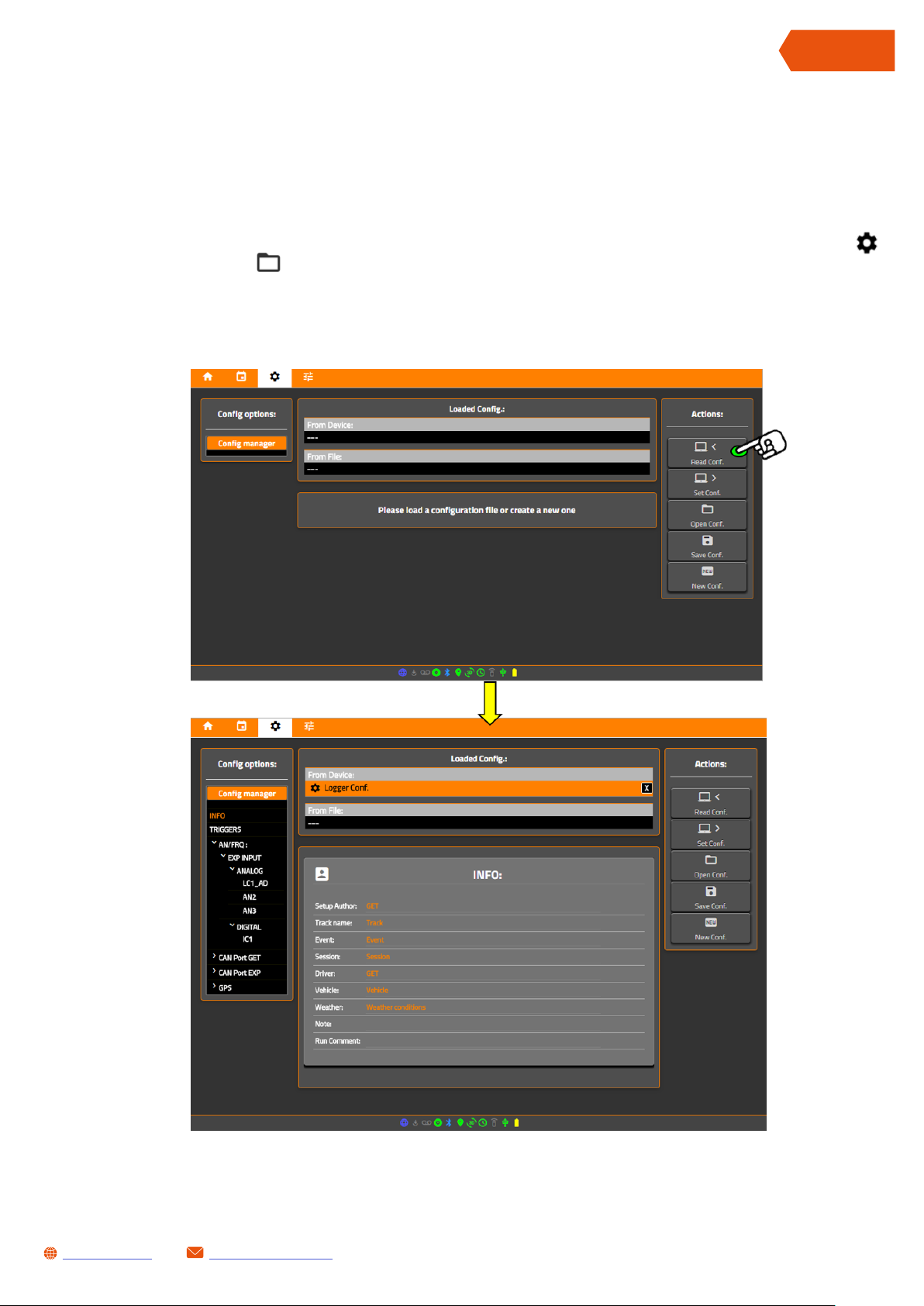
12.5.1 GET DATA LOGGING CONFIGURATION FROM SL1
Internal SL1 Data Logging Configuration be download as follows:
• Connect SL1to a PC (see chapter 12 .1)
• Open Data Logging Configuration page by pressing Log Config button or click NavBar icon
• Click < Read Conf. button to import Data Logging Configuration from SL1:
ENGLISH
Once configuration has been loaded, its components will be list on Config manager area (left
column): click once to open relative configuration panel.
[email protected]www.getdata.it
23
Page 24
ENGLISH
SL1 DATALOGGER User Manual Rev.AA
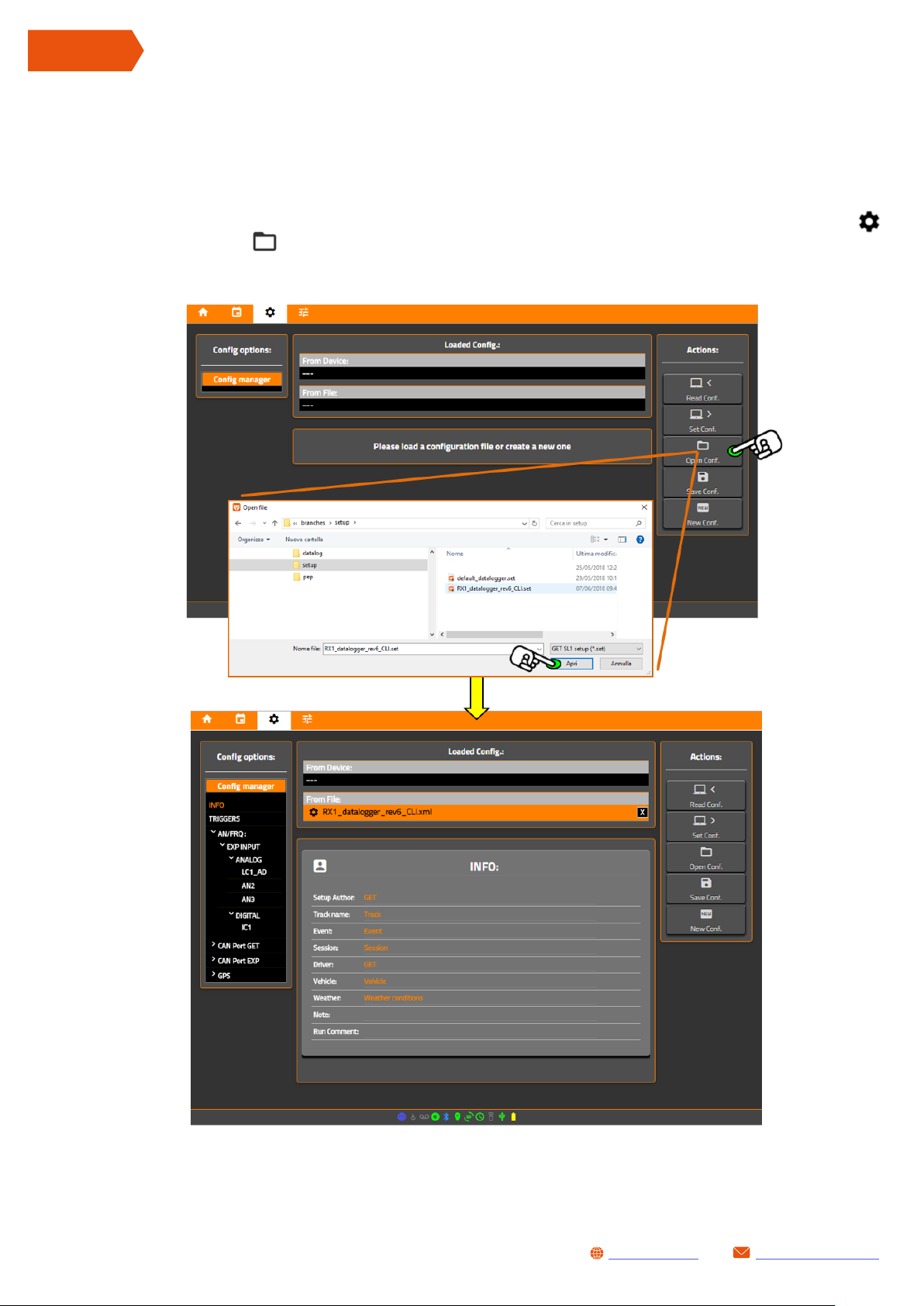
12.5.2 OPEN SAVED DATA LOGGING CONFIGURATION FILE (.set)
Saved Data Logging Configuration file can be load for editing or to update SL1 as follows:
• Run LynXLog
• Open Data Logging Configuration page by pressing Log Config button or click NavBar icon
• Click Open Conf. button to import Data Logging Configuration from SL1 and select a saved
configuration file
24
Once configuration has been loaded, its components will be list on Config manager area (left
column): click once to open relative configuration panel.
[email protected]www.getdata.it
Page 25
SL1 DATALOGGER User Manual Rev.AA
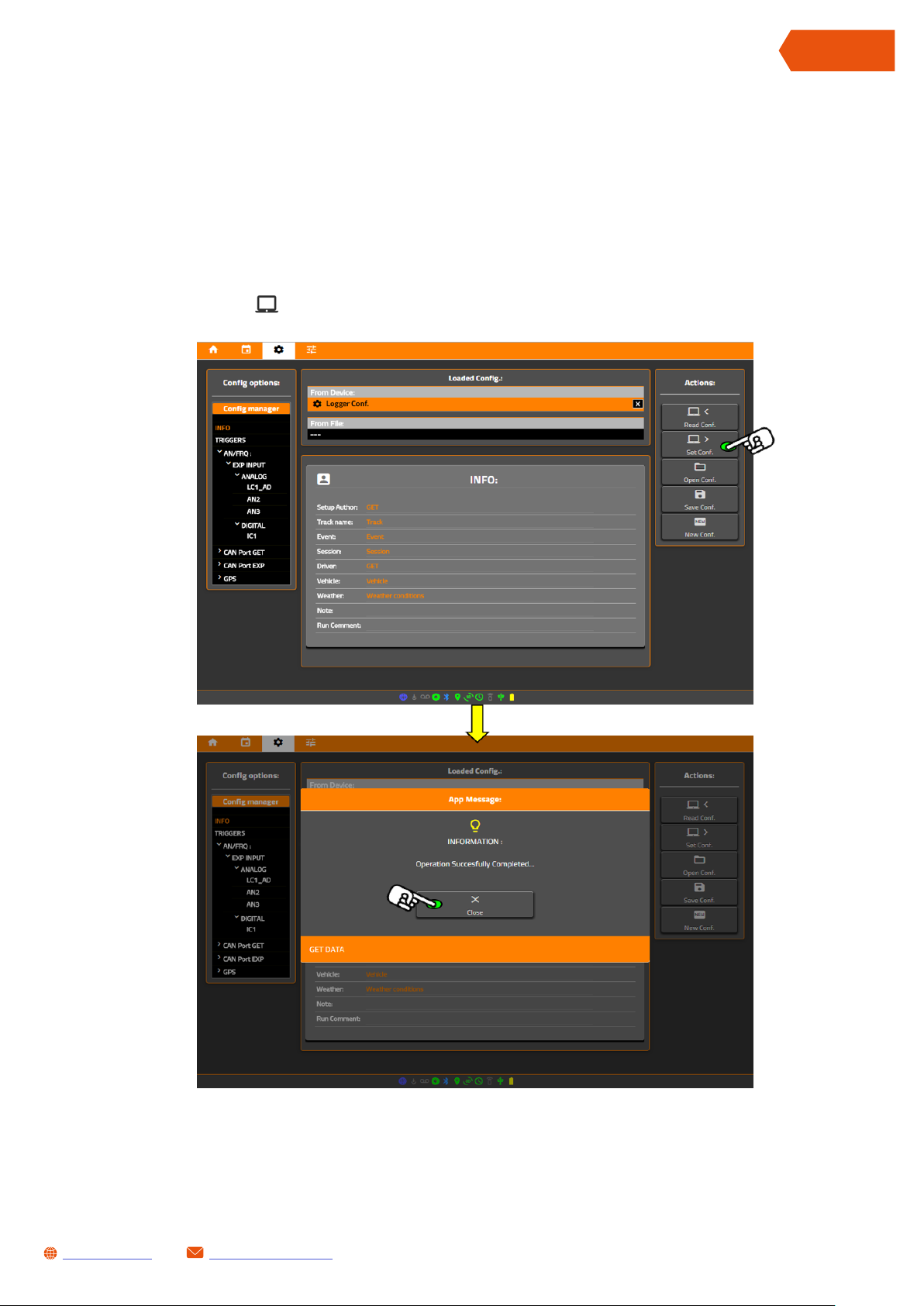
12.5.3 UPLOAD DATA LOGGING CONFIGURATION TO SL1
When you change something in Data Logging Configuration file, it must be send to SL1 to apply
new settings. Proceed as follows:
• Connect SL1 to a PC (see chapter 12 .1)
• Make sure that desired Data Logging Configuration has been loaded (see chapters 12. 5.1 and
12.5.2)
• Click > Set Conf. button to import Data Logging Configuration from SL1:
ENGLISH
• During upload process LEDs will flash a couple of time: this indicates that SL1 is applying new
Data Logging Configuration. At the end of operation a message will be displayed on screen.
[email protected]www.getdata.it
25
Page 26

ENGLISH
SL1 DATALOGGER User Manual Rev.AA
12.5.4 EDIT DATA LOGGING CONFIGURATION
Data Logging Configuration option structure:
INFO
TRIGGERS Define start and stop data log rules
AN/FRQ
CAN PORT GET CAN Bus port 1 (available in MAIN connector)
CAN PORT AUX CAN Bus port EXP (available in EXP connector)
GPS
By click on every option (relative table will be displayed): edit desired parameter (see Appendix 1
for further explain).
All information useful to identify Run, vehicle,
driver, etc...
Physical input channel configuration sort by
function:
ANALOG (AN1,AN2,AN3 - EXP connector)
DIGITAL (IC1 available in MAIN connector)
GPS channels (latitude, longitude, numberof
received satellites, GPS speed, etc.)
26
[email protected]www.getdata.it
Page 27

SL1 DATALOGGER User Manual Rev.AA
12.6 CHANGE SL1 HARDWARE SETTINGS
LynXLog can modify some SL1 hardware settings (such as GPS Dynamic or LEDs brightness).
Proceed as follows:
• Connect SL1 to a PC (see chapter 12 .1)
• Open Setting page by pressing System button or click NavBar icon
ENGLISH
This page allows to:
• View SL1 information (firmware version etc.)
• Synchronize system clock by pressing Set Clock button
• Set LED and/or GPS dynamic by pressing Set Device button
• Reset Run session counter by pressing Reset Run button
• Read system settings by pressing Refresh button
• Turn off the system by pressing Power Off button
[email protected]www.getdata.it
27
Page 28
ENGLISH
SL1 DATALOGGER User Manual Rev.AA
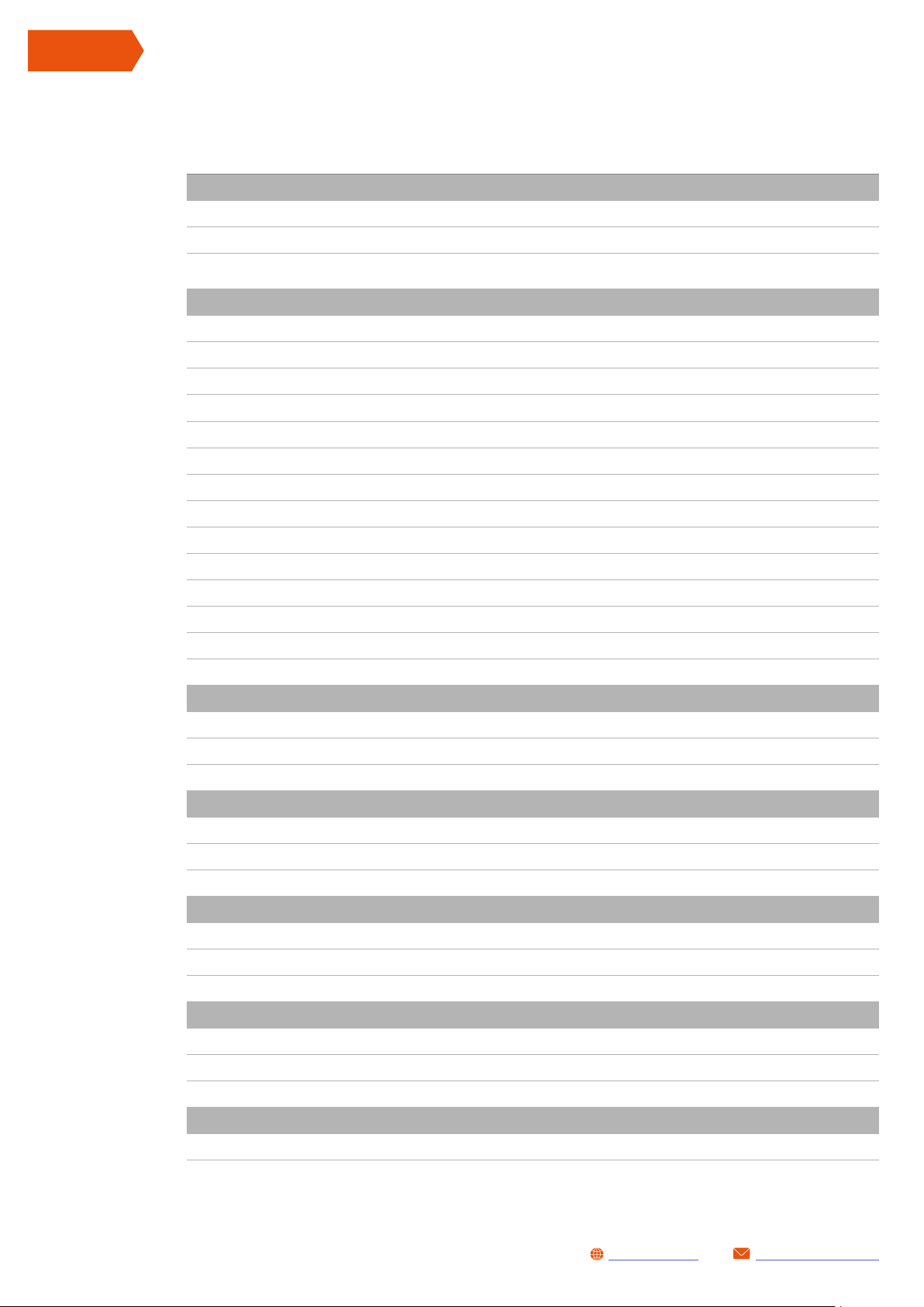
13 SL1 TECHNICAL CHARACTERISTICS
Electrical characteristic:
Main Power Supply inlet: 9-18 VDC
Optional Power Supply inlet: 5 VDC (mini USB port)
Auxiliary Output voltage
(for ext. sensors power supply):
System Characteristic:
Built-in backup battery : 3.7VDC rechargeable LiOn Battery
Built- in memory : 7 GB Flash
System Clock: Built in Real Time Clock (RTC) and GPS clock
Built in GPS characteristics : Sensitivity: 167dB - Update rate:10Hz (up to 18Hz) with ext active antenna
System built-in sensors: 9-axis Inertial platform with Sensor Fusion Technology (3D accel. and 3D gyro)
5VDC - 70mA max.
GPS LED status:
System LED status:
Logging LED status :
GPS antenna connector: SMA
Case type: High – strength plastic case
Case Dimensions: 21mm x 62mm x 79mm (without harness and GPS connector)
Weight: 167 g
IP grade: IP 67
Firmware updates:
Harness specifications:
SL1 Main cable: 9 poles HRS connector (DF62W-9EP-2.2C) – cable length: 150mm
SL1 Expansion cable : 8 poles JST connector (08T-JWPF-VSLE-D) – cable length: 150mm
SL1 USB cable: Sealed Mini USB connector – cable length 500mm
Standard Input port characteristics:
Analog signal input : 3 analog input port (signal range 0-5V)
Frequency input: 1 frequency input (frequency range 20kHz) for 0-5V RPM or SPEED signals
Beacon input: 1 beacon input for lap triggering (signal range 0-5V)
Data Bus characteristics:
✓
✓
✓
✓ (via WiFi or via USB)
28
CAN port : 2 High Speed 2.0 ports (125 – 250- 500 kb/s, 1Mb/s) Intel/Motorola format
Serial port: 1 RS232 communication port
Other port: 1 K-line communication port
Connectivity:
USB 2.0 Port:
BLE:
WiFi :
Software:
Desktop Software SL1 Logger Tool & WinTAX4 Analysis Software
✓
✓
✓
[email protected]www.getdata.it
Page 29

SL1 DATALOGGER User Manual Rev.AA
APPENDIX 1 DATA LOGGING CONFIGURATION DETAILS
Some examples here described will help the end user to add new channels into SL1 Data Logging
Configuration (called also setup) and how to change other parameters.
We’ve already talk about setup structure:
SL1 config
GROUP CATEGORY DESCRIPTION RELATED TO
INFO - Information about track, driver Data archiviation
TRIGGERS - Start / Stop data logging rules Data logging
ENGLISH
ANALOG (AN1..AN3)
AN/FRQ
DIGITAL (IC1)
CAN Port GET USER CAN
CAN Port EXP USER CAN
GPS GPS Channels related to GPS module Data logging
Contain settings of analogue
channels inputs
Contain settings of frequency
channels input
USER CAN: contains configured
channels of CAN0 port
(MAIN conn.)
USER CAN: contains configured
channels of CAN1 port
(EXP conn.)
Data logging
Data logging
Data logging
Data logging
Related Group options are available by click on relative Config Manager box item.
Following steps assume that reader has already open a valid data logging configuration (see
chapter 12. 5.1 and 12.5.2) to edit.
[email protected]www.getdata.it
29
Page 30

ENGLISH
SL1 DATALOGGER User Manual Rev.AA
1 SET INFO
INFO panel can be opened by click once on Config Manager INFO label:
Here you can set following items:
• Setup Author: name of configuration author
• Track name: set track name (it’ll change data archiviation path)
• Event: assign an event name
• Session: assign session name (it’ll change data archiviation path)
• Driver: set driver name
• Vehicle: set vehicle name (it’ll change data archiviation path)
• Weather: set weather conditions
• Note: add note to acquisition
• Run comment: add a comment to Run file
Changes can be done by click on item value.
Configure as needed and update SL1 configuration if all changes has be done.
About archiviation path: Track name, Session and Vehicle items will affect target folder during
data file saving as follows:
Base directory \ Track \ Session \ Vehicle Name \ Run_name\....downloaded Run file
Where:
30
Base directory: it is the main folder of storage path - set in DATA page (see chapter 12.2).
Track: it is the first sub directory of storage path – its value is set by Track name in INFO panel.
Session: it is the second sub directory of storage path – its value is set by Session in INFO panel.
Vehicle Name: it is the third sub directory of storage path – its value is set by Vehicle in INFO
panel.
Run_name: it is the last sub directory of storage path. Its name is Run_ followed to a progressive
session index number created by the data logger.
[email protected]www.getdata.it
Page 31

2 SET TRIGGERS
TRIGGER panel can be opened by click once on Config Manager TRIGGERS label.
By default SL1 data logging is set as Manual: click over it and select desired channel from
dropdown list.
PLEASE NOTE: channel list may change based on configured channels
SL1 DATALOGGER User Manual Rev.AA
ENGLISH
If selected channel is different than Manual Log Trigger Table will be populated of all necessary
options to configure automatic data logging:
Configure as needed and update SL1 configuration if all changes has be done.
[email protected]www.getdata.it
31
Page 32

ENGLISH
SL1 DATALOGGER User Manual Rev.AA
3 AN/FRQ PANEL PHYSICAL INPUTS: AN1..AN3, IC1
AN/FRQ panel can be opened by click once on Config Manager AN/FRQ label.
This panel allows to configure SL1 analogue and frequency inputs.
To configure a channel press EDIT button (or double click on channel label in Config manager
list): Channel Management Window will be displayed.
32
Channel Management Window allows to edit:
• Name: channel name.
• Log frq: logging frequency. If this parameters is None, the channel will not be logged and it will
not be available in analysis software*.
• Decimal Places: how many decimal places you wish to have.
• Unit: this parameter define measurement unit of the channel.
• Calibration Type : you can chose the type of channel calibration
• Calibration Value : you can insert calibration values
• Channel Description : you can insert a comment for the channel, it will displayed when mouse
hover channel name.
Configure as needed and update SL1 configuration if all
changes has be done.
* PLEASE NOTE: Log Frq can be change directly in AN/FRQ table
[email protected]www.getdata.it
Page 33
SL1 DATALOGGER User Manual Rev.AA
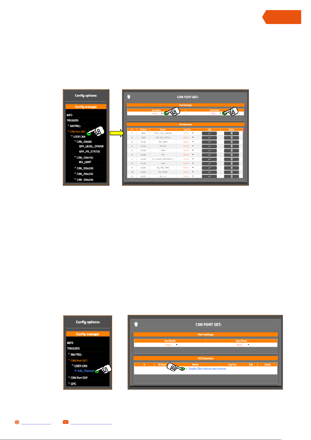
4 CAN PORT GET AND CAN PORT EXP PANEL
CAN Port GET or CAN Port EXP panel can be opened by click once on Config Manager CAN Port
GET or CAN Port EXP labels.
This panel allows to configure SL1 CAN buses properties and relatives channels.
ENGLISH
Here you can set following CAN port properties:
• Bus Speed: with this parameter you could set bus CAN bus bit-rate between available values
• Byte Order : with this parameter you could set CAN bus data format between available values:
Intel: Little Endian byte order
Motorola: Big Endian byte order
4.1 ADD NEW CAN CHANNEL
New channel can be added by click on Add Channel label in Config Manager or in the last row of
channel table.
[email protected]www.getdata.it
33
Page 34
ENGLISH
SL1 DATALOGGER User Manual Rev.AA
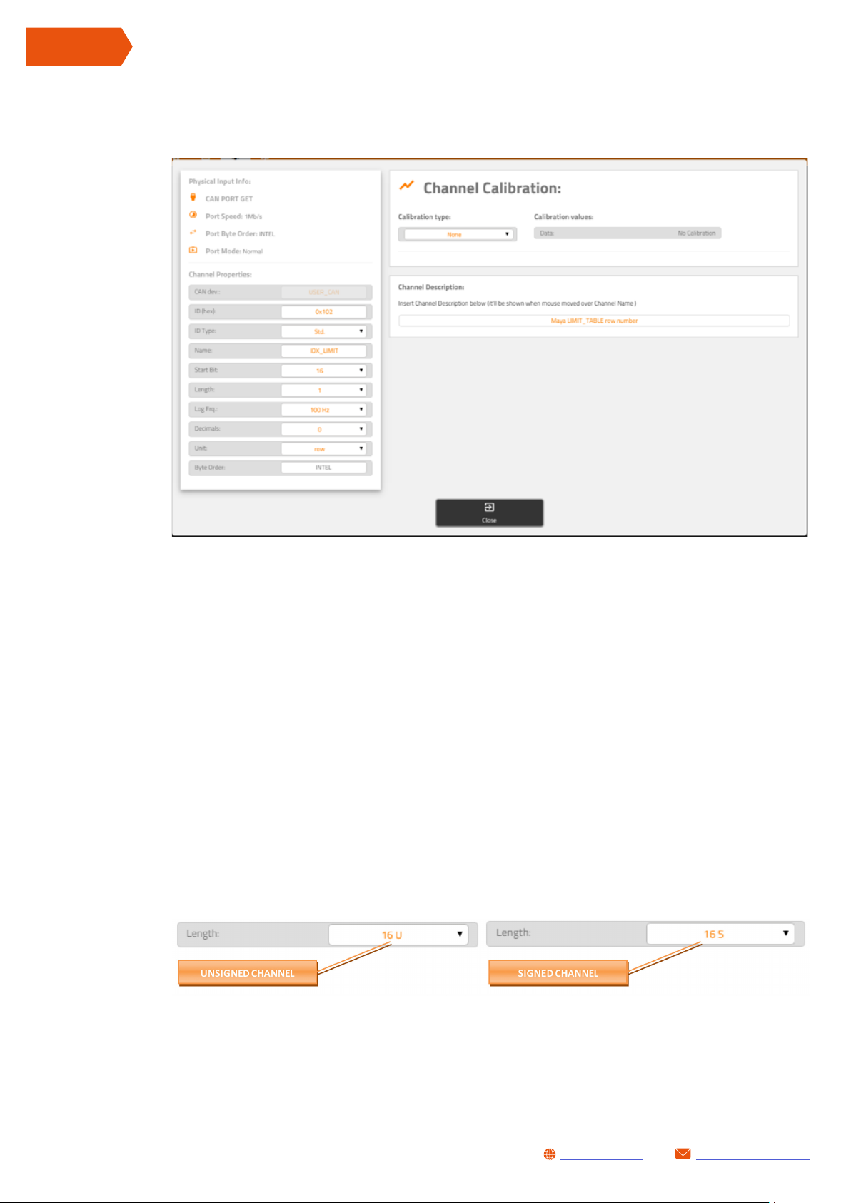
Now Channel Management Window will be displayed: set parameters as needed.
Here you can set:
• ID (hex): define ID number of channel message in hexadecimal format. PLEASE NOTE: you can
insert ID number both with or without 0x prefix, it doesn’t matter.
• ID Type: define if ID length is standard (11 bit length identifier) or extended (29 bit length
identifier). PLEASE NOTE: normally ID below 0x7FF are standard, over this value they are
mandatorily
• Name: define channel name (e.g. IDX_LIMIT).
• Start bit: this parameter define the position (inside CAN message ID) that contains first data
bit to be associated to the channel.
• Length: define bit length of CAN channel. PLEASE NOTE: this parameter define also if channel
is signed or unsigned, see below:
34
[email protected]www.getdata.it
Page 35
SL1 DATALOGGER User Manual Rev.AA
ENGLISH
• Log Frq.: logging frequency. If this parameters is None, the channel will not be logged and it
will not be available in analysis software. PLEASE NOTE: this parameter can be changed also
in Channel Table.
• Decimals: how many decimal places you wish to have (set 0 if you need integer values ).
• Unit: define channel measurement unit
• Byte Order: with this parameter you could set CAN bus data format between available values:
Intel: Little Endian byte order
Motorola: Big Endian byte order
PLEASE NOTE: this options is available only for channels more or equal 16 bit length
• Calibration Type : you can chose the type of channel calibration
• Calibration Value : you can insert calibration values
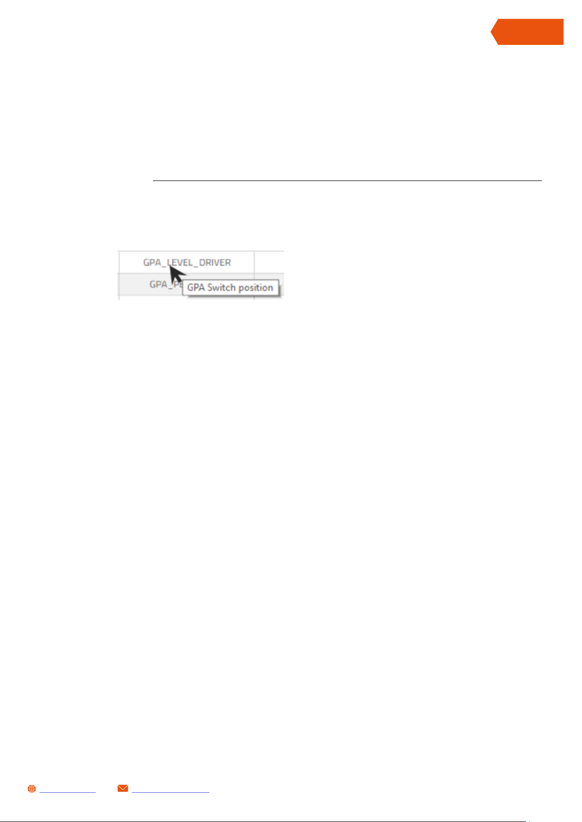
• Channel Description : you can insert a comment for the channel, it will displayed when mouse
hover channel name.
Configure as needed and update SL1 configuration if all changes has be done.
[email protected]www.getdata.it
35
Page 36
ENGLISH
SL1 DATALOGGER User Manual Rev.AA
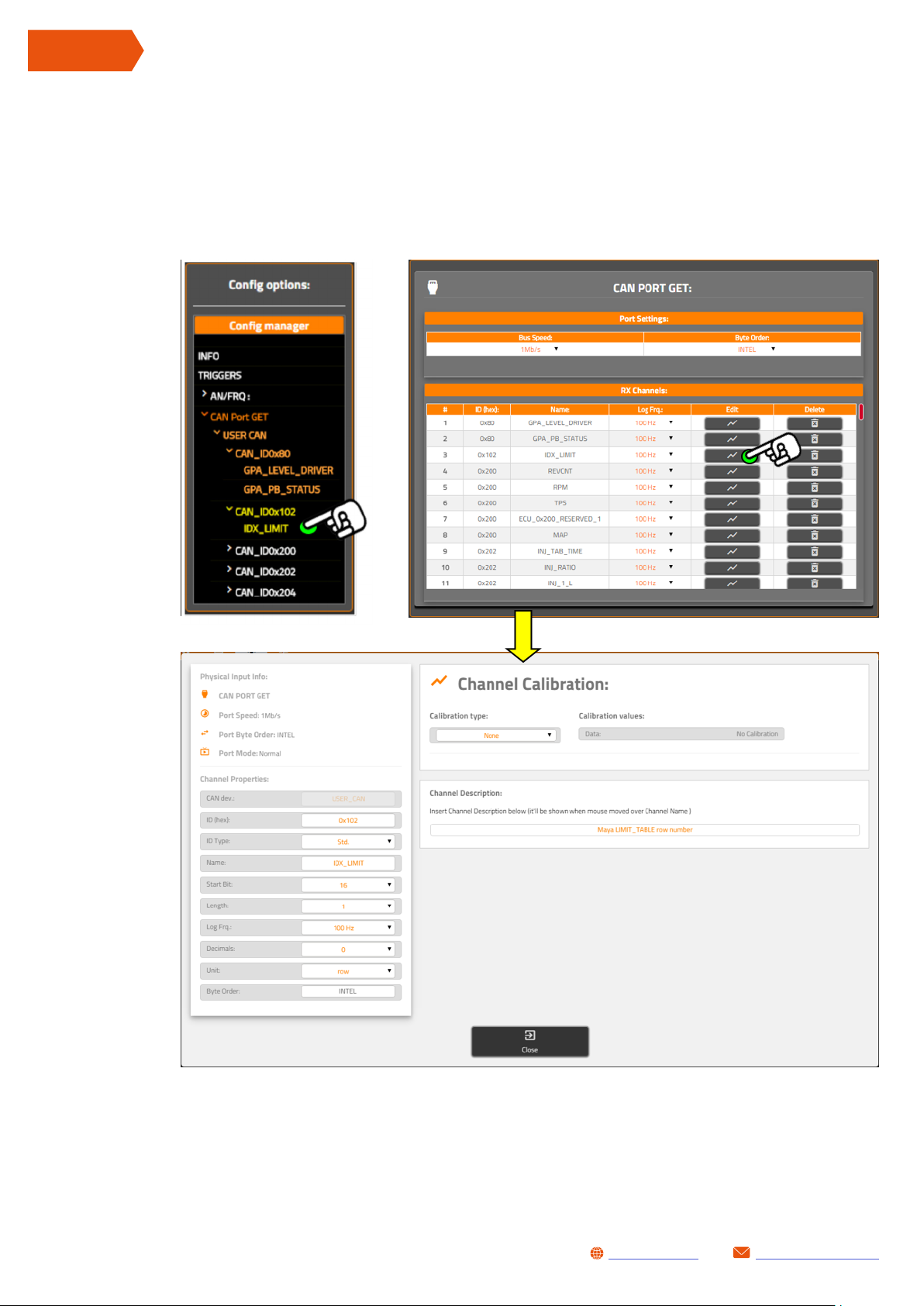
4.2 EDIT EXISTING CAN CHANNEL
To configure a channel press EDIT button (or double click on channel label in Config manager
list): Channel Management Window will be displayed.
36
Change settings (see previous chapter).
Configure as needed and update SL1 configuration if all changes has be done.
[email protected]www.getdata.it
Page 37
5 GPS PANEL
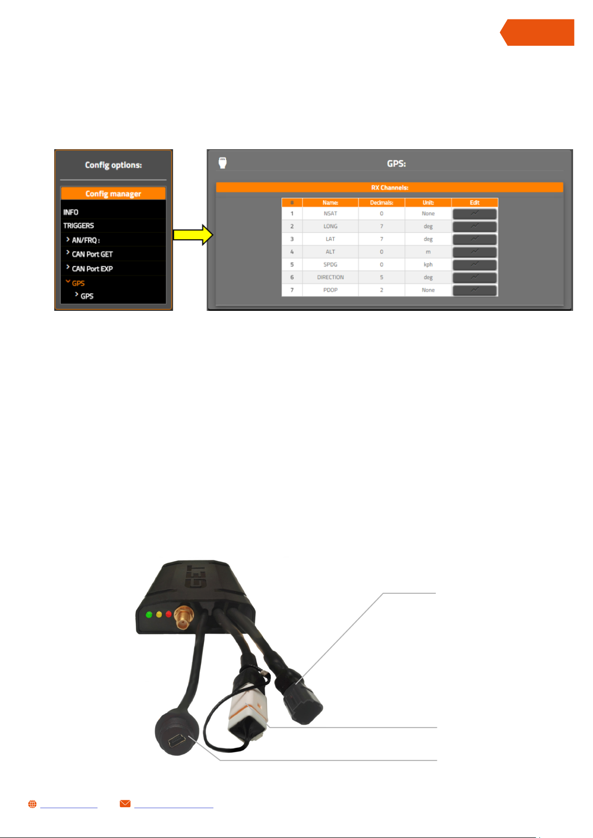
GPS panel can be opened by click once on Config Manager GPS label.
This panel allows to see GPS channels logged by SL1.
SL1 DATALOGGER User Manual Rev.AA
ENGLISH
GPS channels aren’t editable.
APPENDIX 2 PINOUTS
Following chapters will show pinout of all connector in SL1 dataloggers.
1- Main connector
2- EXP Connector
3- USB Connector
[email protected]www.getdata.it
37
Page 38
ENGLISH
SL1 DATALOGGER User Manual Rev.AA
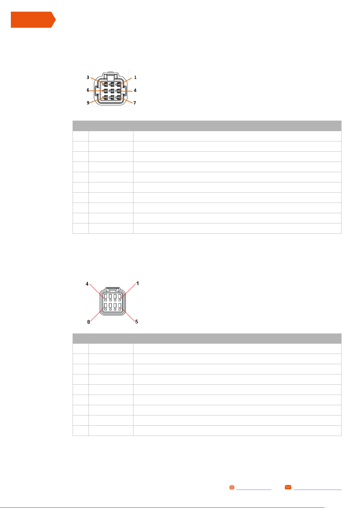
1 MAIN CONNECTOR
PIN SIGNAL NAME DESCRIPTION
1 VPWR Power supply Positive
2 GNDPOW Power supply Ground
3 CAN0L CAN Port GET - CANL signal
4 CAN0H CAN Port GET - CANH signal
5 GNDSEN Auxiliary power and analog/frequency input ground
MAIN connector
Front view
(wiring get out from rear part)
MAIN connector Pinout
6 S L1TOE X T Reserved
7 E XT TO SL1 Reserved
8 IC1 Frequency input (0-12V)
9 BEACON Reserved
2 EXP CONNECTOR
PIN SIGNAL NAME DESCRIPTION
1 KL Reserved
2 GNDSEN Auxiliary power and analogue/frequency input ground
EXP connector
Front view
(wiring get out from rear part)
EXP Connector Pinout
38
3 CAN1L CAN Port EXP - CANL signal
4 CAN1H CAN Port EXP - CANH signal
5 AN1 Analogue input 1 (0-5V)
6 5VAUX Auxiliary power out (5VDC)
7 AN2 Analogue input 2 (0-5V)
8 AN3 Analogue input 3 (0-5V)
[email protected]www.getdata.it
Page 39

3 USB CONNECTOR
PIN SIGNAL NAME DESCRIPTION
1 USB + USB +5V signal
2 USB N USB Data N signal
3 USB P USB Data P signal
4 ID USB ID signal
5 USB - USB GND signal
SL1 DATALOGGER User Manual Rev.AA
USB connector
Front view
(wiring get out from rear part)
USB Connector Pinout
ENGLISH
[email protected]www.getdata.it
39
Page 40
ENGLISH
SL1 DATALOGGER User Manual Rev.AA
APPENDIX 3 WIRING LOOMS FOR SL1 CONNECTION
Following chapter illustrate S L1 harness.
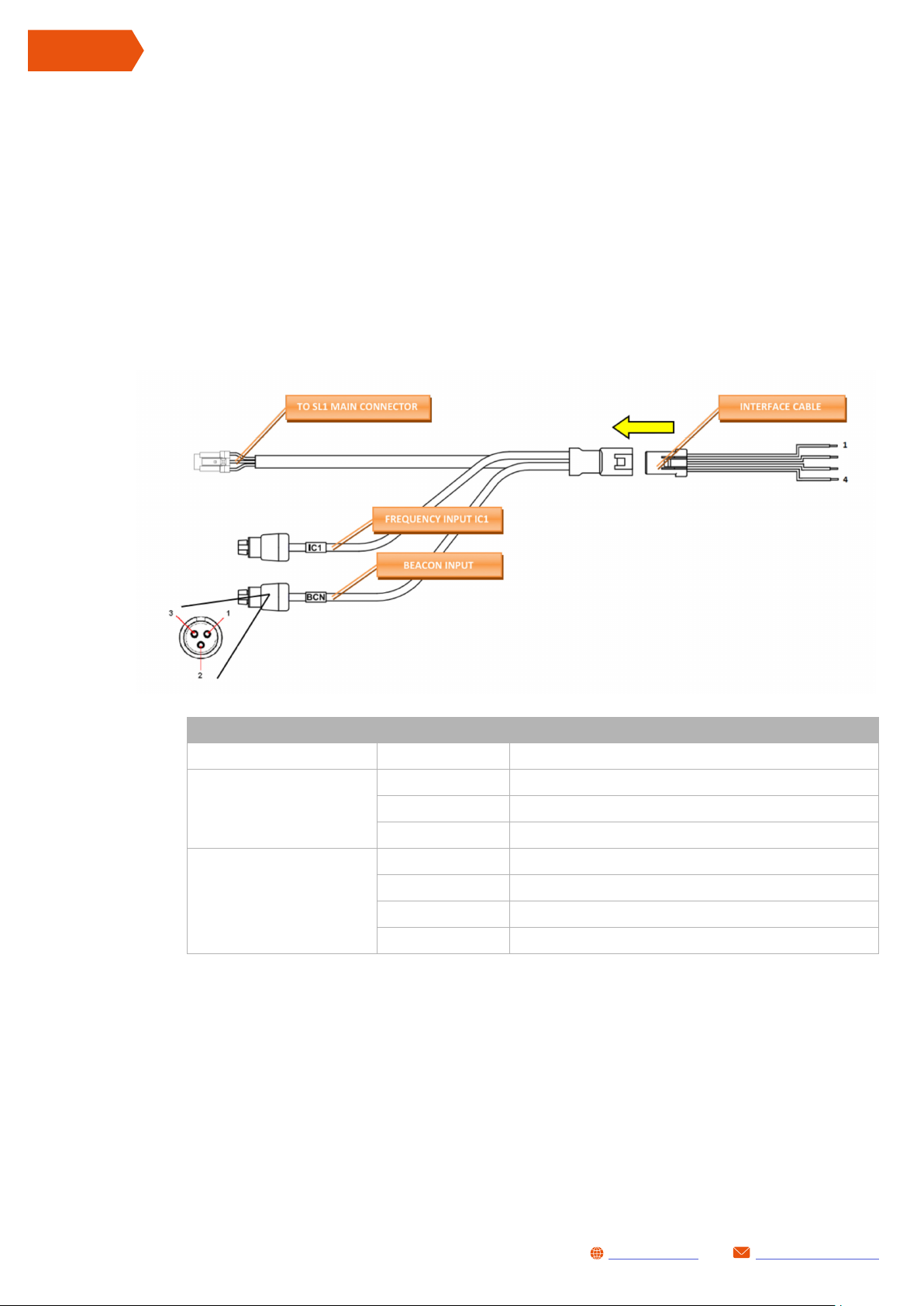
1 MAIN POWER/IC WIRING CODE GL-0178-AA
MAIN/POWER wiring loom code GL-0178-AA. This wiring loom has to be connected to MAIN
connector (SL1 datalogger).
MAIN/POWER connector pinout
CONNECTOR/CABLE PIN DESCRIPTION
1 + Power Supply
IC1
BCC
INTERFACE CABLE
2 Input signal
3 Ground (GND SEN)
1 +Power supply Positive
2 Power supply Ground (GNDPWR)
3 CAN Port GET - CANL signal
4 CAN Port GET - CANH signal
Please note: this cable can be combined with cod. GL-167-AB to easily connect GET ECUs plus a
frequency signal (such as RPM or speed sensor).
40
[email protected]www.getdata.it
Page 41

SL1 DATALOGGER User Manual Rev.AA
2 EXPANSION WIRING CODE GL-0179-AA
EXPANSION wiring loom code GL-0179-AA. This wiring loom has to be connected to EXP
connector (SL1 datalogger).
ENGLISH
EXP connector pinout
C PIN DESCRIPTION
AN1
AN2
AN3
CAN EXP
1 + 5 VDC (VREF)
2 Input signal
3 Ground (GND SEN)
1 CAN Port EXP - CANL signal
2 CAN Port EXP - CANH signal
3 NC – not connected
4 NC – not connected
• CONNECTOR EXP: you need to connect this to EXP connector of S L1
• CONNECTORS AN1…AN3: analogue inputs (example: potentiometer, thermocouples, etc)
• CONNECTOR CAN EXP: second CAN port (CAN Port EXP)
[email protected]www.getdata.it
41
Page 42

ENGLISH
SL1 DATALOGGER User Manual Rev.AA
3 MULTILINK WIRING CODE GL-0167-AB
Connectors position in MULTILINK wiring loom code GL-0167-AB
• ECU CONNECTOR: input for GP1/RX1 ECUs family or lambda module LC1-EVO (data via
CAN Bus)
• GPA CONNECTOR: input for GPA SWITCH module
• SL1 CONNECTOR: input for the connection of S L1 datalogger (MAIN connector).
• PWR CONNECTOR: use it as inlet to power the system. PLEASE NOTE: all connected
devices will turns on (e.g ECU, SPA SW...)
PWR connector pinout
Connector cable PIN DESCRIPTION
1 +Power supply Positive
PWR
2 Power supply Ground (GNDPWR)
42
[email protected]www.getdata.it
Page 43

APPENDIX 4 SL1 CONNECTION DIAGRAMS
Some connections examples are showed in follows chapters:
4 RX1/ GP1 ECUS - SL1 BATTERY LESS CONFIGURATION
PLEASE NOTE:
If OP T.1 is used, all connected devices are powered without need to start engine
SL1 DATALOGGER User Manual Rev.AA
ENGLISH
PWR
GL-0167-AB
[email protected]www.getdata.it
43
Page 44
Page 45

Page 46

[email protected]www.getdata.it
 Loading...