

Athena 6000, 6200 Instruction Manual
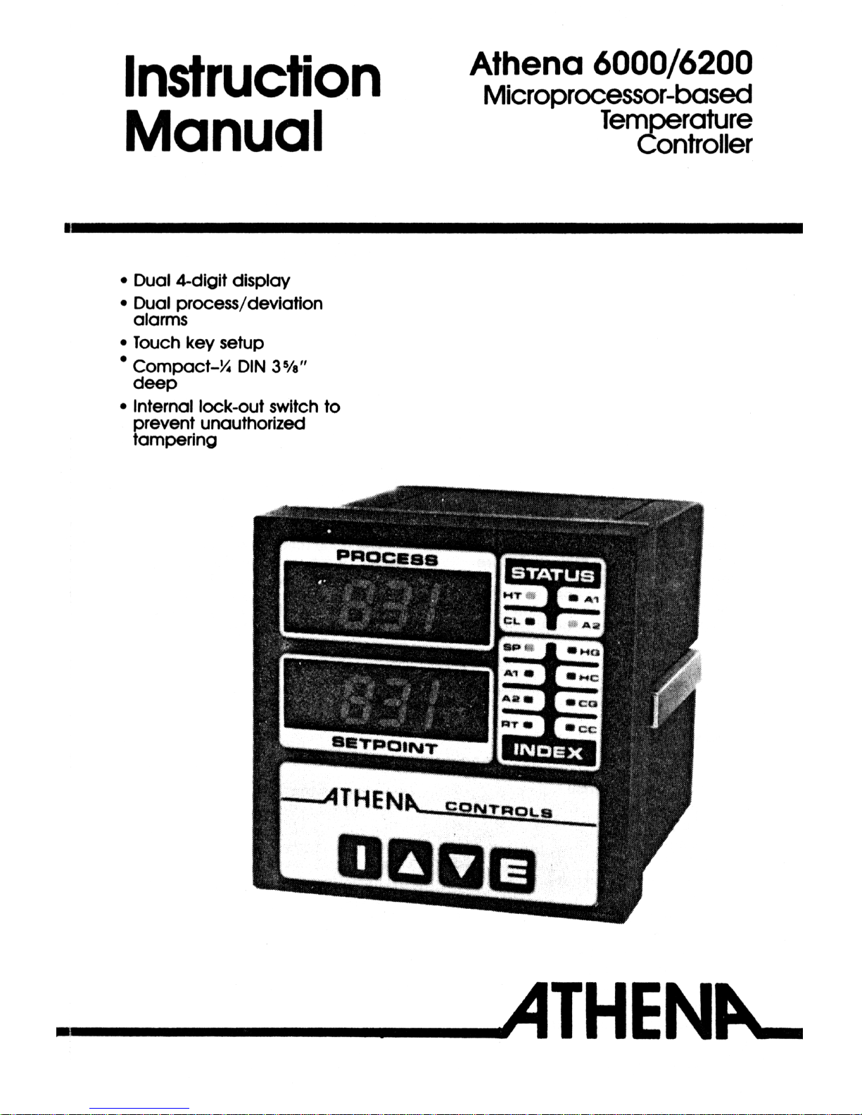

Athena
6000/6200
Microprocessor-based Temperature Controller
Designed for the user
Athena’s
unique
new
6000
microprocessor-based controller
was developed to satisfy the needs
of actual end users, designers, and
specifiers. Data was gathered on
the temperature controller features,
functions, and performance capabilities that they desired. Then
Athena designed a controller to
satisfy them.
Dual
lndication
Now you can compare process
temperature and setpoint
at a
glance - hands free. This dual
digital
display concept has formerly
only been available in high priced
multifunction process controls.
Microprocessors reduce size,
add extras
By using microprocessor
hardware and a highly sophisticated
software package, Athena designers
and engineers have included more
features than have ever been
available before in a controller this
size. Incorporating two digital
displays, touch-key
operation,
software
linearized
and
stabilized
thermocouple input with 3-mode PID
action heat/cooling control and dual
alarms,
ºF to ºC
conversion,
alarms
that can be energized for temp
rise/fall
and selectable as process
or deviation type, and a program
restart circuit that eliminates
program lock-up due to transient
voltage
spikes
or line voltage
“brown out.” Program automatically
restarts within 2
milliseconds
after
condition passes.
PID
Control
Three mode (Proportional,
lntegral, and Derivative) action
eliminates offset (droop) as cooling
and heating requirements change in
the process, and provides fast
output response to rate of change
and reduces temperature overshoot
and undershoot.
Thermocouple linearization
The 6000 has a program to
linearize signal input from the
thermocouple. Without it, temperature controllers have accurate
temperature indication over only
certain
portions of the scale.
Contents
General:
Introduction
Configuration:
Output Forms
Alarm Types
ºC/°F
Installation
lnstructlons:
Unpacking
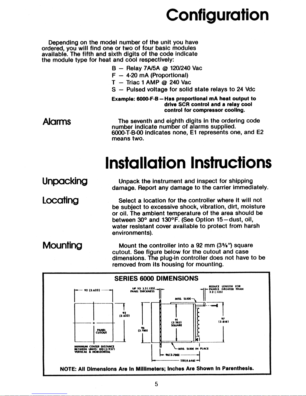
Locating
Mounting
Terminal Designations
Output Modules
Wiring Examples
Internal
Switches
Thermocouple lnstallation
PAGE
2
4-5
4-5
4-5
5
5
5
6
6-7
6-9
10
11
Operating Instructions:
Control Panel Description
Start-up
Parameter Entry
Heat Galn Setting
Rate
Setting
Examples
Cool Gain
Setting
Trouble Shootlng
Repairs and Warranty
PAGE
13
13
13-14
15
15
15
15
16
16
2

Specifications
Inputs:
Line
Voltage
Sensor
Power
consumption:
Ranges
available:
Accuracy:
Temperature
stability:
Cold end
tracking:
Operating ambient
for
rated accuracy:
Maximum lead
resistance for rated
accuracy:
Series
mode noise
rejection:
Common mode
noise
rejection:
T/C break
protection:
Dual display:
Display update rate
and filtering
ºF/ºC:
Alarm 1 & 2:
Outputs:
- B
Relay (time
proportioning)
-F Current
proportional
-S Pulsed
voltage
-T
Triac
(time
proportional
-
E1 & E2
Auxiliary
alarm relays
(on/off)
Filtered
LED
display:
T/C linearization:
Connections:
Dimensions:
Mounting:
Weight:
Recorder output:
(RTD
only)
120/240
Vac
50,60
Hz
T, J or K thermocouple or Platinum 100Ω at 0°C
Less than 6 VA (Instrument)
J couple 0-1400°F (0-760%)
K couple 0-2000°F (0-1093ºC)
±1 digit of full scale
5 µV/ºC Max 3 µV/ºC typ.
0.05ºC/°C ambient
0 to 55%
Thermocouple: 100Ω
RTD: 10Ω/lead
60 dB
120 dB
upscale standard
Process temp displayed continuously; setpoint or other
parameters updated on lower display
Greater than 5 times per second.
Analog and digital filtering techniques increase stability of
process & display.
Internal switch selection-process, setpoint and alarms
affected.
Adjustable over full range of control. LED displays alarm
status. 3 amp relay at 120 Vac normally open contact.
Reverse acting relay by switch selecting or low alarms.
Process/deviation mode selectable (internal switch).
Available heating only or heat/cool
SPST relay 7 amps resistive at 120 Vac, 5 amp resistive
at 240 Vac, 50 VA inductive
4-20 mAdc into 500 ohm max.
0-20 Vdc pulsed time proportioning signal for driving solid
state relays 500 ohms maximum input impedance
Solid state plug-in triac output. Rated 1 amp holding &
10 amps inrush
SPST relays, rated 3 amps at 120
Vac
4 digits for process, 4 digits for parameters.
Continuously calculated and updated using rom based
algorithm.
Inputs and outputs vla barrier strips with U.L. approved
Iocking sems terminals.
Front panel: 96mm x 96mm x 22mm
Case: 92mm x 92mm x 118mm
Depth behind panel: 96mm (approx. minus panel thickness)
Channel slides and screws
2 lb
1 mV/ºC for degree reading unit
0.1 mV/ºC for 1 10 degree reading unit
3
+10
-15%

Front Panel Adjustments
Touch Key
Index:
Allows the following adjustments to be selected.
1) set
point temperature 0 to span
2) alarm one temperature setting 0 to span
3) alarm two temperature setting 0 to span
4) rate with tracking reset (1:6ratio) ** 0 to 120 sec
5) heat gain *** 1 to 400
6) heat cycle time * 1 to 120 sec
7) cool gain *** 1 to 400
6) cool cycle time * 1 to 120 sec
up/down keys: increases/decreases values of above adjustments
writes selected values to
nonvolatile
memory
Enter:
Internal switches/jumpers
A) 4 position dip switch
1) selects ºF/°C display
2) selects energized alarm two on hi/low (dev + / dev -) temperature
3) selects energized alarm one on hi/low (dev + / dev -) temperature
4) selects process or deviation alarm function
B) 2 position dip switch
1) selects reduced rate gain
2) locks out front panel parameter entry excepting set point
NOTES: *** setting to zero disables output
* setting to zero initiates 60 millisecond timebase for ultra fast cycling.
Use with external solid state relays.
**Setting to zero disables reset and rate actlon for proportional only control.
To order see price sheet C-5-82
General
Congratulations on
purchasing
an
outstanding
temperature controller Ingenious use of
microprocessor technology has given you an
economical, compact controller that:
1.
2.
3.
4.
5.
Accurately measures, linearizes and displays
temperature in
ºF
and
ºC.
Digitally
enters and displays control and alarm set
points
as well as heat and cool
gains,
cycle times,
and user simplified rate and reset action.
Can be switched
configured
for
high
and low
process alarms or deviation
alarms.
Can be field converted from relay output “B”, to
solid state relay "T" to solid state relay driver "S"
or to a 4-20 MA output SCR driver "F", with
independent outputs for heat and cool.
Will remember its “entered” settings after power
failure or shut-off and not “Go To Sleep”.
CAUTION: HIGH VOLTAGE AND HIGH TEMPERATURES CAN
CAUSE INJURY AND ARE A FIRE HAZARD. PLEASE READ
ALL INSTRUCTIONS, HAVE ONLY SKILLED PROFESSIONALS
WIRE THE
UNIT,
AND USE AN APPROVED TEMPERATURE
AND/OR PRESSURE SAFETY CONTROL. EVEN THE BEST
COMPONENTS CAN BE DAMAGED OR MAY NOT FAIL SAFE.
4
x
 Loading...