

Page 1
1
Instruction
Manual
ANALOG TEMPERATURE
CONTROLLERS
SERIES
2000 / 3020
Page 2

2
Page 3

Introduction
Precautions
Congratulations on your purchase of an Athena®Series 2000 or
Series 3020 analog temperature controller. It is a U.L. listed,
1/4-DIN controller for use in a variety of applications. Standard
features include time proportioning with auto-adjusting cycle
time, djustable bandwidth (for on-off to wide band proportioning), and offset (manual reset). Outputs include relay, triac, or
mAdc types.
If you have questions or require any assistance with your controller or with any temperature control problem, please contact
your Athena representative or call technical support at 1-800782-6776. Outside the USA, please call 610-828-2490.
3
After unpacking, inspect the instrument for any physical damage that may have occurred in shipping. Save all packing materials and report any damage to the carrier immediately.
©Copyright 2004, Athena Controls, Inc.
Table of
Contents
Output Configurations 3
Preliminary Instructions 3
Mounting 3
Power Wiring Circuits 4
Thermocouple Wiring Circuits 6
RTD Wiring Circuits 6
Thermocouple Placement 6
Operation 7
Front Panel Layout 8
Output Function Switches 8
Adjustments 9
Maintenance 11
Specifications 12
Ordering Codes 13
Troubleshooting 14
Warranty 16
Unit Repairs 17
Page 4
4
Preliminary
Instructions
Output
Configurations
Type “B” Relay with 7 A at 120 V and 5 A at 240 V
contacts, on-off and time proportioning
Type “F” Signal current, 4-20 mAdc
Type “L” Relay with 7 A at 120 V and 5 A at 240 V
contacts, on-off, reset switch
Type “T” Solid state relay 1 A, 120/240 V resistive
load; 1 A, 120/240 V, 10 A inrush,
inductive load (not U.L. rated)
Type “S” Pulsed 20 Vdc, for driving solid state
relays
Unpacking
Carefully unpack the instrument, inspect for shipping damage. Report any damage to the carrier immediately.
Locating
Select a location for the controller where it will not be subjected to excessive shock, vibration, dirt, moisture or oil. The
ambient temperature of the area should be between 30° and
130° F. (Dust, oil, water resistant cover is available to protect
from harsh environments. Contact factory for details.)
Mounting
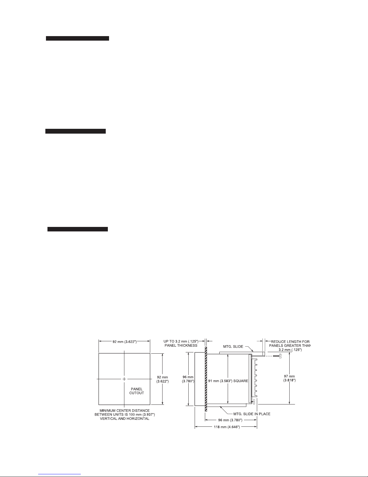
Mounting
Mount controller into 92 mm (3-5/8”) square cutout (1/4DIN). See Figure 1 for cutout and case dimensions. The
plug-in controller does not have to be removed from its housing for mounting.
Remove the two screws in the back of the case that hold the
mounting slides, and then remove the slides. Insert case
from front of panel and reinstall the two slides and two
screws. The length of the slides must be reduced if the controller is to be mounted in an extra thick panel. If the controller has been unplugged from its housing, the top of the
housing can be determined by the serial number tag.
Figure 1: Cutout and case dimensions
Page 5
5
Power Wiring
Circuits
Consult serial tag on the unit and select power wiring diagram for the model specified. All wires are connected to the
terminals on the back of the case. Screw terminals are provided. Make appropriate connections using proper size wire
for rated controller load power circuits. (On -B output model,
use AWG #14 wire; for -F, -S and -T outputs use #14, 16, or
18 wire.) The unit can be supplied with 120 V or 240 Vac,
50/60 Hz. Select proper terminal for the voltage used.
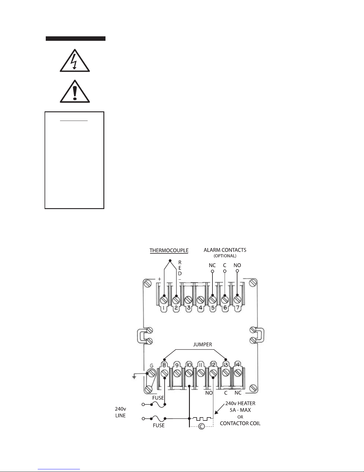
Typical Wiring Diagrams
-T & -B Outputs
B-Type - 840 W maximum. 120 Vac heater. (Non-inductive
loads only) For larger loads, replace heater connections with
contactor, as required. Maximum inductive load rating is 3 A
at 120 V and 1.5 A at 240 V. The N.C. contacts can be used
for cooling.
T-Type - solid state relay with SPST contacts. The -T units can
handle contactors or resistive loads up to 1 A with 10 A
inrush maximum. For -T units use a 1 A, 250 V fast blow fuse.
-L Output (Limit Controller)
Wiring can be similar to that shown for “B.” The controller’s
relay is de-energized until the reset button on the front panel
is momentarily pressed. The relay will energize if the sensor
temperature is below setpoint. The common and N.C. terminals can be used to indicate alarm condition remotely when
wired to lights, bell, etc.
CAUTION
Possible fire hazard. Because
these controls or
associated equipment may not
always fail safe,
an approved temperature and/or
pressure safety
control should be
used for safe
operation.
Figure 2a: Typical 240 Vac for -B & -T Output
Page 6
6
Power Wiring
Circuits
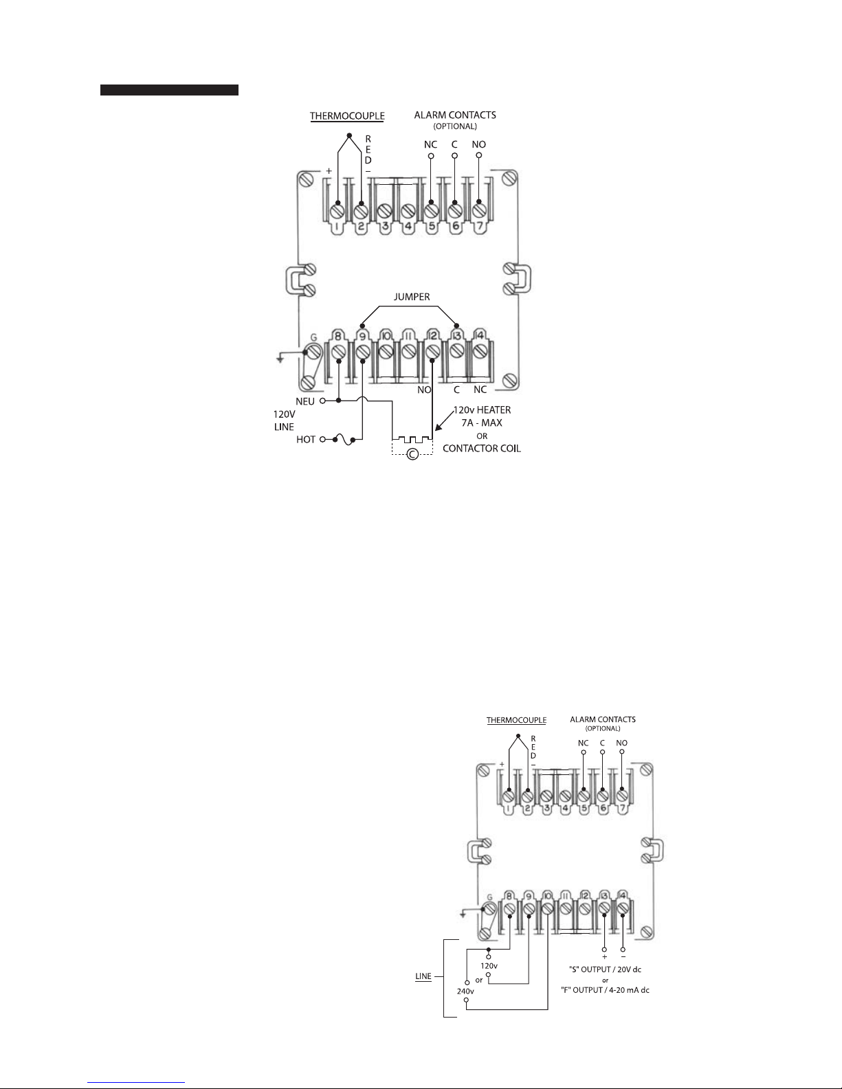
Figure 2b: Typical 120 Vac for -B & -T Output
Typical Wiring Diagrams
Figure 3: Typical 120/240 Vac
for -F & -S Output
-F, -S Output - 120/240 Vac
The -F output is 20 mA at the low temperature end of the proportional band and 4 mA at the upper end of the proportional
band. Maximum load resistance is 1000 ohms. The -S output
is a time-proportioned 20 Vdc signal. These controllers cannot be used with a device that does not have an isolated
input. An ungrounded thermocouple must be used if there is
ac leakage or a ground in the input of the device connected
to the controller’s output.
Page 7

7
Thermocouple
Wiring Circuits
Use thermocouple and extension wire that conforms to the
appropriate thermocouple type specified on the serial number
tag. In thermocouple circuits, the negative lead is colored red.
Extension wires must be of sufficient size so that on long runs
the thermocouple circuit resistance does not exceed 100
ohms.
Do not run thermocouple leads in the same conduit as the
power lines. If shielded thermocouple wire is used, terminate
the shield only at the controller end using the corner screw
provided for that purpose.
Standard Thermocouples
I.S.A. Type Materials Color Code
(U.S.A.)
J Iron-Constantan (I/C) White (+)/Red(-)
K Chromel-Alumel (C/A) Yellow (+)/Red (-)
T Copper-Constantan Blue (+)/Red (-)
RTD Wiring
Circuits
Thermocouple
Placement
The 2002 and 3220 units are designed for 100 ohm platinum
RTDs. Two-wire RTDs are connected to terminals -1 and -2
with a jumper connecting 2 to 3. Keep leads short and use
heavy gauge copper extension wires if necessary, to minimize
lead resistance. For long runs 3-wire RTD should be used and
wire gauge should be sufficient that resistance does not
exceed 10 ohms.
DO NOT RUN RTD LEADS IN THE SAME CONDUIT AS POWER LINES.
If shielded RTD wire is used, terminate the shield only at the
controller end, using the corner screw provided for that purpose.
Proper thermocouple placement can eliminate many problems in the system. The probe should be placed so that it can
detect any temperature change with little thermal lag. In a
process that requires fairly constant heat output, the probe
should be placed close to the heater. In processes where the
heat demand is variable, the probe should be close to the
work area. Some experimenting with probe location can often
provide optimum results.
In a bath process, the addition of a stirrer will help to eliminate
lags. Since the thermocouple is basically a point measuring
device, putting more than one thermocouple in parallel will
provide an average temperature reading and produce better
results in air-heated processes.
NOTE: RTDs
tend to be shock
sensitive and
require extra care
in handling and
installation
Page 8

8
Operation
The typical control system contains the sensor, controller (2000/3020)
and the process (load). The sensor produces a small signal proportional to the measured temperature of the process. This signal is
amplified by the controller, where it is compared with setpoint temperature. If the temperature of the sensor is below setpoint, the output circuitry will be actuated to apply power to the process. This is
indicated by means of an LED light in the lower center of the front
panel. The deviation meter will swing to the extreme left. It will remain
there until the temperature of the probe rises to within 50 °F of setpoint, and then will continue to rise to the null point (zero degree
deviation). The deviation meter accurately displays the difference
between the probe’s (process) temperature and the desired setpoint
temperature.
-B - Relay Output
The “B” output is a relay rated at 7 A, 120 Vac and 5 A, 240 Vac.
These contacts can be wired to provide power to a heater within the
above rating. A contactor can be operated to handle a larger load.
Solenoids can be operated to control oil or gas heaters.
The controller operates as a narrow band controller when the band
adjustment is set at the narrow position. As the band is widened, the
unit becomes a time-proportioning controller, which provides close
temperature control. The percentage of the time when the relay is
energized is varied by the controller to meet the load requirements.
Maximum cycle time setting is 15 seconds.
-F - Current Output
Current proportional output of the -F unit is a 4 to 20 mAdc signal into
1000 ohm maximum. This output can be used to drive power controllers, motor positioners or electropneumatic actuators.
-S - Pulsed Voltage Output
This output is similar to the -F output with the exception of a pulsed
time base rather than a fully proportional current output signal. This
output is designed to drive solid state contactors.
-L - Limit Control Output
The -L output unit is designed as a high limit controller and is a variation of the -B output controller. The time proportioning circuit, along
with the proportional band and offset (manual reset) adjustments,
have been eliminated. A reset pushbutton has been added to the
front panel and extends beyond the door. When power is applied, the
controller will energize except for the output relay, which will operate
after the reset button is pushed. The green LED indicates the safe or
non-alarm condition. When the measured temperature exceeds the
setpoint, the relay will de-energize and the green LED will turn off.
Lights or horns can be driven directly, because the SPDT relay contacts are rated 7 A at 120 Vac or 5 A at 240 Vac.
-T - Solid State Output
The -T output unit has a solid state relay with SPST contacts rated at
1 A, 120/240 Vac (10 A inrush maximum). These contacts can be
wired to provide power to a heater within the above ratings, and a
contactor can be added to handle larger loads. Solenoids can be
operated to control oil or gas heaters.
NOTE: To reach
the plug-in module,
push reset button
while opening the
door, and then
remove two (2)
screws.
Page 9

9
Front Panel Layout
Layout of the front panel is shown below. To reach the adjustments, swing the top of the door forward and down. The proportional band adjustment is on the right side and sets the
gain of the controller. The offset (manual reset) adjustment is
on the left and corrects for offsets from the setpoint temperature. The output indication (LED) can be seen through a window in the door.
Units ordered with Option A (3-Mode PID) will not have a
manual reset adjustment. Instead, these units have an automatic rate adjustment on the front panel and an automatic
reset selector switch inside the unit.
Output Function
Switches
Output Function Switch Chart
Figure 5: Output Function Switch Chart
NOTE:
—SWITCH NO. 4 IN “ON” POSITION IS FOR: “B” OR “T” OUTPUTS WHEN DRIVING MECHANICAL
DEVICES, E.G., CONTACTORS.
—SWITCH NO. 4 IN “OFF” POSITION IS FOR “T”, “F”, OR “S” OUTPUTS WHEN DRIVING DEVICES
THAT CAN WITHSTAND RAPID CYCLING, E.G., SOLID STATE DEVICES, SOLENOIDS, ETC.
Page 10

10
Output Function
Switches
How to Configure Output Function Switches
There is a switch assembly on the bottom board (see bottom
board illustration). This four-position switch regulates cycle
time and output selection. It is factory-configured for the plugin output ordered. Check the output function chart to make
sure the configuration is correct for your application. Figure 5.
Switches 1&2: These switches act together to select either
proportional current output or one of the time
proportioning cycle times. (See the output
function switch chart.) Use longest times to
get best relay life expectancy. If meter shows
temperature swings following each “on” cycle,
select a faster time to reduce “ripple.”
Switch 3: Selects either on/off or proportional action.
“On” provides proportional action. “Off” provides on/off action.
Switch 4: Selects output for either mechanical or solid
state relays.
On: Provides slow proportional times for
mechanical relays
Off: Provides 20 mAdc when used with the “F”
module or fast time proportioning times
when used with “S” or “T” modules.
NOTE: Switch 4 changes the cycle times in conjunction with
switches 1 and 2. Check output function switch chart.
NOTE:
Reconfigured or
field-modified units
should always be
checked to assure
that output switch
positions are correct.
Proportional Band Adjustments for All Outputs
The proportional band adjustment widens or narrows the
band over which proportional action occurs. Too narrow a
band can cause the temperature to swing about the setpoint.
This can be seen on the deviation meter. Too wide a band
can cause an error between the setpoint and the actual temperature (droop error) as measured at the sensor.
Proper setting of this adjustment is the point where the temperature swings just stop. When adjusting the proportional
band control, do so in small increments, allowing time
between each adjustment for the process to stabilize.
Turning the adjustment in a clockwise direction widens the
proportional band and should reduce swings to straight line
control with most processes.
Offset (Manual Reset)
After the proportional band is set, the process temperature
may stabilize at a point other than the setpoint, high or low, as
shown on the deviation meter. This can be corrected with the
offset (manual reset) adjustment. If the deviation meter indicates a low temperature, turn the offset (manual reset) adjustment clockwise (+ direction) until the deviation meteris at
zero. Turn the offset (manual reset) adjustment counter-clock-
Adjustments
Page 11

11
wise (- direction) for high temperature as indicated by the
deviation meter.
NOTE: If close control cannot be obtained after carefully
repeating the above procedures, check to see if the thermocouple probe is in good contact with the heated process, and
if the heaters are correctly sized for the application.
Applications involving large changes in setpoint operating
temperature, or large load changes, will require readjustment
of the proportional band and offset (manual reset) pots.
How to Set the Alarm
Deviation alarms are triggered when the temperature deviates from the setpoint by a predetermined amount. Units can
be ordered with either high, low, or high/low alarms.
1. Turn the adjustment clockwise to widen the span
between the process setpoint and the alarm, or
counterclockwise to narrow it. (Full clockwise
should be about 50 °F (30 °C) from setpoint. Full
counterclockwise should be only 5 °F (3 °C) from
setpoint.
2. To check the actual alarm point, simply change
the setpoint until the deviation meter reads zero.
Then move it downward (for high alarm) or
upward (for low alarm). When the alarm is triggered, check the deviation meter -- it will show
deviation in the amount you’ve set on the alarm.
Optional 3-Mode (PID)
How to Set Reset, Proportional Band, and Rate
Auto reset action automatically, but slowly, corrects droop
error in proportionally controlled processes. Ideal reset time
is one half the period of oscillation of the process. Slower settings are safe, but sluggish. Faster settings will cause continuous oscillation.
1. For slow processes, move switches 1 and 2 off,
set rate slow, proportional band wide, and go to
Step 4. Otherwise:
2. Set reset time (internal switches are indicated on
automatic reset switch chart below). Use the
fastest time (0.8 minutes) for very fast processes,
1 minute for most others, as a first try.
3. Set the proportional band to full wide (270°
clockwise). Make sure rate is full fast, turned full
clockwise, as well.)
4. Plug controller in, turn your process on.
5. Observe warm-up. If the process overshoots setpoint and cycles in continually decreasing waves
Adjustments
Page 12

until it finally stabilizes, the reset time is correct.
Then proceed to Step 7. If it continues to oscillate,
reset it to short, continue with Step 6.
6. Set reset switches to the next slowest time.
Repeat Step 5. Continue changing settings until
the process stabilizes.
7. Turn proportional band pot 1/4 turn toward nar-
row (counterclockwise). Process could begin to
oscillate again. If it doesn’t, proceed to step 8. If it
oscillates, back up 1/8 turn clockwise.
8. Tighten proportional band by turning the pot
counterclockwise. Observe the process. If oscillation continues, widen back by 1/8 turn. Continue
until the process stabilizes.
9. Set the rate. Rate action responds to sudden load
changes and anticipates power output requirements. It also helps to eliminate overshoot on startup. Rate should be approximately 1/6 of reset time.
If the reset time is 0.8 minutes, the rate should be
turned clockwise. For 1 minute, mid-position. For 2
minutes, it should be at least 3/4 full; for 4 minutes
full slow.
10. Turn the process off to cool, then start up
again observing the warm-up curve. If it takes
the process too long to reach the setpoint, make
the rate faster by turning it back clockwise. If, on
the other hand, it overshoots the setpoint by an
amount that is not acceptable, slow the rate by
turning the pot counterclockwise.
Adjustments
NOTE:
Each
process will tolerate
differing warm-up
curves. Often, a fast
warm-up is more
important than the
elimination of overshoot. If it is important to eliminate
overshoot, a slower
setting should be
used, but it will also
add to the time it
takes the process to
reach the setpoint.
In general, it is
best to maintain the
tightest parameters
possible (narrow
proportional band,
faster reset, faster
rate) that still deliver
optimal process
response.
Maintenance
11. Fine tuning. If, after having established parameters, you’d like to improve response, it can be
accomplished by a simple “trial and observation”
technique.
A. Change a parameter (either rate or proportional
band) by a significant value (the pots generally
need to be moved 30° to produce an effect).
B. Change the setpoint.
C. Observe the way the process responds
-- if response is improved (i.e., faster rise, less
overshoots, faster stabilization at setpoint),
retain the new value. If not, return the old value.
D. Try another parameter.
Some preventive maintenance steps on the controllers are:
1. Keep the controller fairly clean, and protect it from
dirt, oil, and corrosion. An optional dust cover is
available for use in hostile environments.
2. Periodically recheck all electrical connections.
CAUTION:
Since the front
panel and the
meter face are
plastic, do not
use solvents to
clean them.
12
Page 13

13
Specifications
Supply Voltage: 120/240 Vac, +10% -15%, 50/60 Hz
Setpoints:
Series 2000
: Analog - single-turn
potentiometer, 270° rotation
Series 3020
: Mechanical digital
potentiometer
Setpoint Repeatability: +/-0.3% of span (Series 2000)
Setpoint Resolution:
Series 2000
: 0.2% of span
Series 3020
: 1 °F or °C
Input: Thermocouple Types J, K, T, R (Series 2000)Types J, K
(Series 3020), range dependent.
Maximum lead resistance 100 ohms for rated accuracy;
cold junction compensation standard. RTD input 100 ohms
platinum at 0°C, DIN (.00385) curve.
Thermocouple
Break Protection: Built-in, failsafe, open sensor, output zero;
Meter units – upscale indication
Cold Junction
Compensation: Automatic electrical
Accuracy: +0.5% of span at calibration points
Indication,
Temperature: Deviation meter +50 °F (+30 °C) of setpoint
Load: LED on when power is supplied to load
Proportional Band: On/off or nominal 5 °F - 50 °F (3 °C - 30 °C)
Offset (Manual Reset): Adjustable over 100% of proportional band
Rate (Derivative): 0.5 to 25 seconds
Reset (Integral): 0.7, 1, 2 or 4 minutes via internal
DIP switches
Alarm: 3 A at 120 Vac
Output: B - SPDT Relay, non-inductive rated
7A/5A max at 120/240 Vac, 50 VA inductive
F - 4 to 20 mAdc into 1000 ohms max load
L - SPDT Relay, non-inductive rated
7A/5A max at 120/240 Vac, 50 VA inductive
S - 20 Vdc into 1000 ohm maximum load
T - 1 A solid-state relay; 10 A max. inrush
Ambient Temp Range: 30° to 130 °F (0 to 55° C)
Weight: 1 lb, 9 oz (709 g)
All specifications subject to change.
Page 14

14
Ordering Codes
Alarms Code
B = High alarm only
C = Low alarm only
D = High and low alarm
0 = None
Control Options
Code
0 = Proportional
(Standard)
A = 3-mode (PID)
Athena’s ZC/PC solid state
contactors, and Series 91 and
93 or Series 19 and 39 SCR
power controllers, can be
added to boost ac load
switching capacity.
The deviation meter spans a
range of +5° and reads in
increments of 0.5°.
Sensor Input Code
0 = Thermocouple
2 = RTD
STANDARD RANGE CODE
Thermocouple
Code Set Range Type
14F 100 to +400°F “T”
03F 0 to +300°F “J”
04F 0 to +400°F “J”
13F -100 to +350°F “J”
16F 100 to +600°F “J”
08F 0 to +800°F “J”
01F 0 to +1000°F “J”
03C 0 to +300°C “J”
05C 0 to +500°C “J”
51F 500 to +1500°F “K”
02F 0 to +2000°F “K”
25F 0 to +2500°F “K”
01C 0 to +1000°C “K”
30F 0 to +3000°F “R”
R
TD (3-wire, 100 ohms)
R26 -200 to +600°F
R81 80 to +120°F
R30 0 to +300°F
R60 0 to +600°F
R10 0 to +1000°F
R11 -100 to +100°C
R23 200 to +300°C
R06 0 to +600°C
Special Options
(Consult Factory)
2
0
0
Output type (Plug-In) Code
B = SPDT Relay, 5 A/7 A
F = 4-20 mAdc
T = SPST SS Relay, 1 A
S = Pulsed 20 Vdc
L = Limit Control
Alarms Code
B = High alarm only
C = Low alarm only
D = High and low alarm
Control Options
Code
0 = Proportional
(Standard)
A = 3-mode (PID)
Athena’s ZC/PC solid state
contactors, and Series 91 and
93 or Series 19 and 39 SCR
power controllers, can be
added to boost ac load
switching capacity.
Sensor Input
Code
0 = Thermocouple
2 = RTD
STANDARD RANGE CODE
Thermocouple
Code Set Range Type
01F 0 to +999°F “J”
05C 0 to +500°C “J”
02F 0 to +1999°F “K”
R
TD (3-wire, 100 ohms)
R06 0 to +600°C 100 ohm
R10 0 to +999°F 100 ohm
Special Options
(Consult Factory)
3 2
0
Output type (Plug-In) Code
B = SPDT Relay, 5 A/7 A
F = 4-20 mAdc
T = SPST SS Relay, 1 A
S = Pulsed 20 Vdc
Page 15

15
Symptom
Controller dead. No output
light, no meter deflection
Probable Cause
- No line voltage input
- Open PC board to backplate connector (defective connector)
- Open power transformer
Symptom
No output, step 1 ok, meter
nulls at ambient
Probable Cause
- External backplate
jumper missing (all models except “S” and “F”)
- Defective relay
- Open heater or heater circuit wiring
Symptom
No output, meter reads full
scale positive, no heat
Probable Cause
- Open thermocouple or
T/C wiring
Symptom
Full output, no control.
Ouput light stays on.
Probable Cause
- Thermocouple connections reversed
- T/C lead wires shorted
between T/C
and control
Symptom
Full output, no control.
Output light goes off. Meter
goes upscale.
Probable Cause
- Relay contacts welded
closed
Troubleshooting
Check
Verify 120/240 Vac, 50/60 Hz input voltage. Check
heater for shorts. Look for open breakers or open
external fuse. Remove input power. Check continuity
through power transformer primary. With ohmmeter,
read between pins: 8 and 9 for 225 or 450 ohms
+/-10% and 8 and 10 for 680 or 1000 ohms +/-10%
Corrective Action
- Replace heater, if shorted
- Restore power
- Replace either power transformer or backplate
connector
Check
If no readings in either step above, remove controller
from housing and repeat resistance measurements as
above, but directly on PC board lands corresponding
to pins 8, 9, and 10. Correct readings indicate open
PC board to backplate connector problem. Incorrect
readings indicate power transformer problems.
Visually inspect relay contacts.
Heater continuity and wiring.
Corrective Action
- Install jumper
- Replace relay if contacts are worn or dirty
- Replace open heater, correct defective wiring
Check
T/C continuity. Disconnect T/C connections from
instrument. Measure T/C circuit resistance. Ohmmeter
should read 100 ohms or less.
Corrective Action
- Replace T/C. Correct defective wiring
Check
Connection polarity. T/C wires are color-coded. Red is
the negative (-) lead. (for U.S.A.) T/C lead wiring.
Corrective Action
- Connect correctly
- Repair or replace
Check
Disconnect power and load. Measure resistance
between pins 12 and 13. Should read infinity.
Corrective Action
- If resistance reading is near 0 ohms, replace relay
Page 16

Troubleshooting
Symptom
Process control temperature differs from setpoint when read
with an external pyrometer.
Deviation meter nulls and
process is stable.
Probable Cause
- T/C lead wires shorted close
to process
- Wrong type of T/C being used,
etc.
- Standard electrical wiring
being used in place of T/C
wire
- Gradient error
Symptom
Temperature overshoots, or
oscillates.
Probable Cause
- Process overpowered
- Bandwidth too narrow
- Process or sensor lag
Symptom
Process control temperature
stabilizes above or below setpoint as read on deviation
meter.
Probable Cause
- Offset (manual reset) incorrectly adjusted
- Partial short to ground in
heater when used on 240 V
line
- No output from suspect con-
trol
- Controller reading other zones
of multi-controlled process
- Full output from suspect con-
trol
- Apparent stabilization from
other zones of multi-controlled
process
- Improperly sized heater
NOTE: Fuse blowing is not caused by
the controller. Blown fuses are caused
by shorts in the heater circuit, and
must be corrected to prevent damage
to the controller.
Check
Check T/C lead wires at back of probe
Wire color indicates type of T/C
Verify type of wire
Corrective Action
- Replace defective wiring
- Install correct T/C for temperature range of instrument. See instrument serial number tag for T/C type.
- Run only T/C wire between process and controller.
- Use electronic indicator in parallel with suspect
instrument’s T/C input.
Check
Check bandwidth
Loose heater or sensor fit. Poor
relative location.
Corrective Action
- Reduce total heater power
- Widen band
- Improve fit, locate closer together
Check
Offset (manual reset)
Heater to ground resistance
Design parameters for process heat required
Corrective Action
- Adjust (+) to increase controlled temp. (-) to
decrease temp.
- Replace defective heater
16
Page 17

17
Two-Year Limited Warranty
THIS EQUIPMENT IS WARRANTED TO BE FREE FROM DEFECTS OF
MATERIAL AND WORKMANSHIP. IT IS SOLD SUBJECT TO OUR
MUTUAL AGREEMENT THAT THE LIABILITY OF ATHENA CONTROLS, INCORPORATED IS TO REPLACE OR REPAIR THIS EQUIPMENT AT ITS FACTORY, PROVIDED THAT IT IS RETURNED WITH
TRANSPORTATION PREPAID WITHIN TWO (2) YEARS OF ITS PURCHASE.
THE PURCHASER AGREES THAT ATHENA CONTROLS, INCORPORATED ASSUMES NO LIABILITY UNDER ANY
CIRCUMSTANCES FOR CONSEQUENTIAL DAMAGES RESULTING
FROM ITS USE OR FROM IMPROPER HANDLING OR PACKAGING
OF SHIPMENTS RETURNED TO THE FACTORY.
COMPONENTS WHICH WEAR OR WHICH ARE DAMAGED BY MISUSE ARE NOT WARRANTED. THESE INCLUDE CONTACT POINTS,
FUSES, ELECTROMECHANICAL RELAYS, AND TRIACS. UNITS
WHICH HAVE BEEN MODIFIED BY A CUSTOMER IN ANY WAY ARE
NOT WARRANTED.
Other than those expressly stated herein, THERE ARE NO OTHER
WARRANTIES OF ANY KIND, EXPRESS OR IMPLIED, AND SPECIFICALLY EXCLUDED BUT NOT BY WAY OF
LIMITATION, ARE THE IMPLIED WARRANTIES OF FITNESS FOR A
PARTICULAR PURPOSE AND MERCHANTABILITY.
IT IS UNDERSTOOD AND AGREED THE SELLER’S LIABILITY
WHETHER IN CONTRACT, IN TORT, UNDER ANY WARRANTY, IN
NEGLIGENCE OR OTHERWISE SHALL NOT EXCEED THE RETURN
OF THE AMOUNT OF THE PURCHASE PRICE PAID BY THE PURCHASER AND UNDER NO CIRCUMSTANCES SHALL SELLER BE
LIABLE FOR SPECIAL, INDIRECT,
INCIDENTAL OR CONSEQUENTIAL DAMAGES. THE PRICE STATED
FOR THE EQUIPMENT IS A CONSIDERATION IN
LIMITING SELLER’S LIABILITY. NO ACTION, REGARDLESS OF
FORM, ARISING OUT OF THE TRANSACTIONS OF THIS AGREEMENT MAY BE BROUGHT BY PURCHASER MORE THAN ONE YEAR
AFTER THE CAUSE OF ACTION HAS ACCRUED.
SELLER’S MAXIMUM LIABILITY SHALL NOT EXCEED AND BUYER’S
REMEDY IS LIMITED TO EITHER (i) REPAIR OR REPLACEMENT OF
THE DEFECTIVE PART OR PRODUCT, OR AT SELLER’S OPTION (ii)
RETURN OF THE PRODUCT AND REFUND OF THE PURCHASE
PRICE, AND SUCH REMEDY SHALL BE BUYER’S ENTIRE AND
EXCLUSIVE REMEDY.
THE SPECIFICATIONS PUT FORTH IN THIS MANUAL ARE SUBJECT
TO CHANGE WITHOUT NOTICE.
Warranty
Page 18

Unit Repairs
It is recommended that units requiring service be returned to an
authorized service center. Before a controller is returned for service,
please consult the service center nearest you. In many cases, the
problem can be cleared up over the telephone. When the unit needs
to be returned, the service center will ask for a detailed explanation of
problems encountered and a Purchase Order to cover any charge.
This information should also be put in the box with the unit. This
should expedite return of the unit to you.
This document is based on information available at the time of its
publication. While efforts have been made to render accuracy to its
content, the information contained herein does not purport to cover all
details or variations in hardware, nor to provide for every possible
contingency in connection with the installation and maintenance.
Features may be described herein which are not present in all hardware. Athena Controls assumes no obligation of notice to holders of
this document with respect to changes subsequently made.
Proprietary information of Athena Controls, Inc. is furnished for customer use only. No other use is authorized without the written permission of Athena Controls, Inc.
Repairs
18
Page 19

19
Page 20

900M002U00 Revision B
Athena Controls, Inc.
5145 Campus Drive
Plymouth Meeting, PA 19462 USA
Tel: 610-828-2490
Fax: 610-828-7084
Toll-Free in USA: 1-800-782-6776
techsupport@athenacontrols.com
athenacontrols.com
For free technical assistance in the USA,
call toll free 1-800-782-6776 or
e-mail techsupport@athenacontrols.com
 Loading...