

Page 1

SERIES
16C
TEMPERATURE/PROCESS
CONTROLLER
Standard Options and
Digital Communications
User’s Guide
Page 2

© Copyright 2004, Athena Controls, Inc.
Page 3

Table of
Contents
For information and
instructions related to
basic operations, refer
to the Series C
operator’s manual
supplied with your
controller.
Options Wiring Diagrams
Dual Alarm Outputs (Options #10 and #22) 1
Dual Open Collector Alarms (Option #20) 2
Dual 24 Volt DC Alarm Outputs (Option #21) 3
Relay, N.O. Alarm Output (Option #23) 4
RS-232 Communications (Option #30) 5
RS-485 Communications (Option #31) 6
Contact/Digital Input with Alarm
(Options #40, #41, #42) 7
Transducer Excitation (Options #50, #51,
#52, #53) 8
Auxiliary Output (Options #60, #61, #62, #63) 9
Remote Analog Setpoint (Options #80, #81,
#82, #83, #84) 10
Guide to Digital Communications
Remote Communications Options 12
Athena+ Protocol 14
- Message Format 15
- Sample Commands 19
- Request Messages 21
- Response Messages 24
- Communications Parameter List 27
- Auxiliary Commands 31
- Communications Error Codes 34
Page 4
1
Dual Alarm
Outputs
Option #10: Dual Alarm Output, N.O.
Option #22: Dual Alarm Output, N.C.
This optional hardware module provides two alarm drive outputs. LED indicators A1 and A2
are used to indicate alarm conditions as configured in the Alarm Menu.
Option Description:
Option 10: Dual alarm, N.O.
Option 22: Dual alarm, N.C. (Note: NC only when power
is applied to unit; otherwise NO)
Load Limits:
Max. Load Current 1 A rms
Min. Load Current 0.5 mA rms
Power Factor Range 0.2 to 1.0 (can drive small
motors, solenoids, valves, and
contactors)
Max. Surge Current
Non-repeating for 1 second 7.5 A
Max. I2T for fusing (0.01 sec) 4.5 amp-squared seconds (1 A -
ABC1 typical fuse)
Page 5

2
Option #20: Dual Open Collectors, NPN, Isolated
with Clamping Diode
Dual Open
Collector Alarms
Option Description: Dual open collectors, NPN, isolated, with clamping
diode
Recommended operating conditions:
Supply Voltage Pins 13 & 14; 200 working Vdc max. (Never exceed
300 Vdc)
Collector Current 50 mA max.
Specifications:
Saturation Voltage 0.3 Vdc min.
1.2 V max.
Collector-Emitter
Breakdown 300 V min.
Isolation Isolation 300 volts ac/dc output-to-output or output-
to-controller
Page 6

3
Dual 24 Vdc
Alarm Outputs
Option #21: Dual 24 Vdc Alarm Outputs
Option Description: Dual 24 V outputs with clamping diodes
Pins 13 & 7 are connected internally
Source current is limited to 25 mA (1000 ohm
resistor)
Open circuit voltage is 25 volts
Isolation: Isolation 300 volts ac/dc either output to
instrument
Page 7

4
Tungsten Lamp, 360 W 120 Vac
Option Description: NO (Normally open) relay contact is closed when
either alarm is active. Jumpers on the board can be
removed to activate the output for a single alarm only:
JP1 - Alarm A1
JP2 - Alarm A2
The relay life is greater than 100,000 operations at 5 operations per second switching full load.
*
Connect load and supply voltage per the following table:
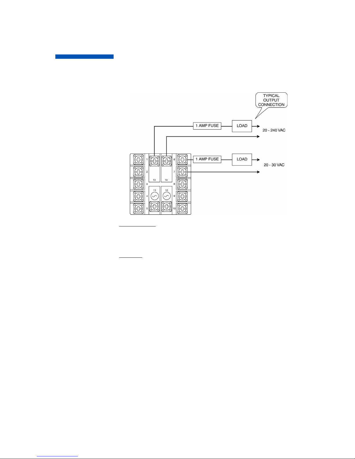
Relay, N.O.
Alarm Output
Option #23: Relay, N.O. Alarm Output
Load Type 5 Amp Voltage Limit
Resistive DC 30 Vdc
Inductive DC (L/R = 7 ms) 20 Vdc
Resistive AC 250 Vac
Inductive AC (pF = 0.4) 150 Vac
Motor, AC, 1/6 hp 250 Vac
*
*
Page 8
5
RS-232
Communications
Option #30: RS-232 (one-to-one) Communications
Option Description: Provides a one-to-one connection between
the controller and an RS-232 port.
Computers, PLCs, or dumb terminals may
be used to set and access controller data.
Page 9

6
RS-485
Communications
Option #31: RS-485 (one-to-many)
Communications
Option Description: Provides one-to-many communications.
If run exceeds 1000 ft., terminate the controller furthest from the computer by connecting a 120-ohm, 1/4-watt resistor between terminals 13 and 14.
*Converter is supplied with a wallplug-mount power transformer.
Page 10

7
Contact/Digital
Input with Alarm
Option Description: Dual function board (functions unrelated)
a. Output alarm is energized when either A1
or A2 is active.
b. Digital input controls Remote Standby, Ramp-Soak
Run/Hold, OR Second Setpoint Select.
Option 40: Active when switch closed.
Option 41: Active when switch open.
Option 42: Active when 5 V input present
Load Limits:
Max. Load Current: 1 A rms
Min. Load Current: 0.5 mA rms
Power Factor Range: 0.2 to 1.0 (can drive small motors, solenoids, valves,
and contactors)
Max. Surge Current,
Non-Repeating for
1 second: 7.5 A
Max. I2T for fusing (0.01 sec): 4.5 amp-squared secs (1A - ABC1
typical fuse)
Contact/Digital
Input with Alarm
Options #40, #41, #42: Contact/Digital Input with
Alarm
Input Option Menu
Page 11
8
Transducer
Excitation
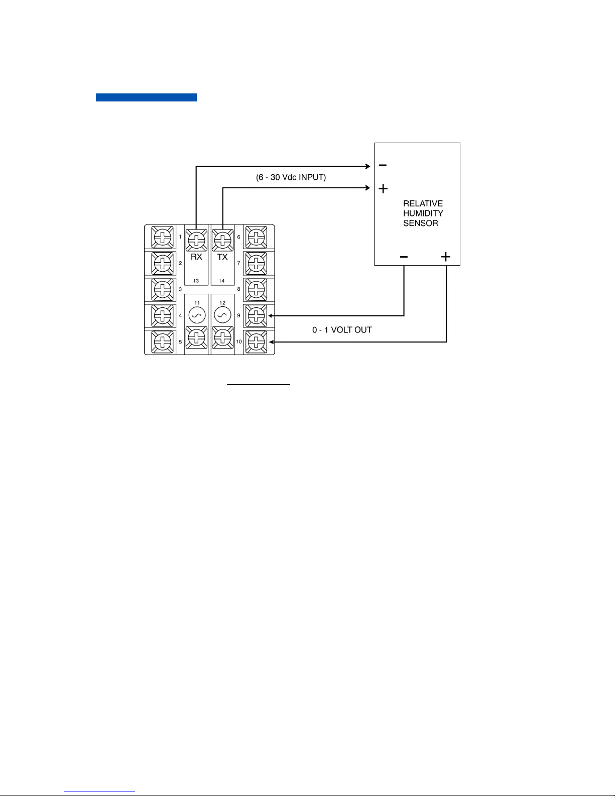
Option #50, #51, #52, #53: Transducer Excitation
Option Description: The transducer excitation option provides power to
remote transducers. The transducer outputs, in turn, provide a signal to the controller input which can be scaled
in the appropriate engineering units.
Option 50: 10 Vdc
Option 51: 12 Vdc
Option 52: 15 Vdc
Option 53: 5 Vdc
All options will provide at least 20 mA. The transducer circuitry is thermally protected
from short circuits.
Page 12
9
Auxiliary Output
Option #60, #61, #62, #63: Auxiliary Output
Auxiliary Output
Input Option Menu
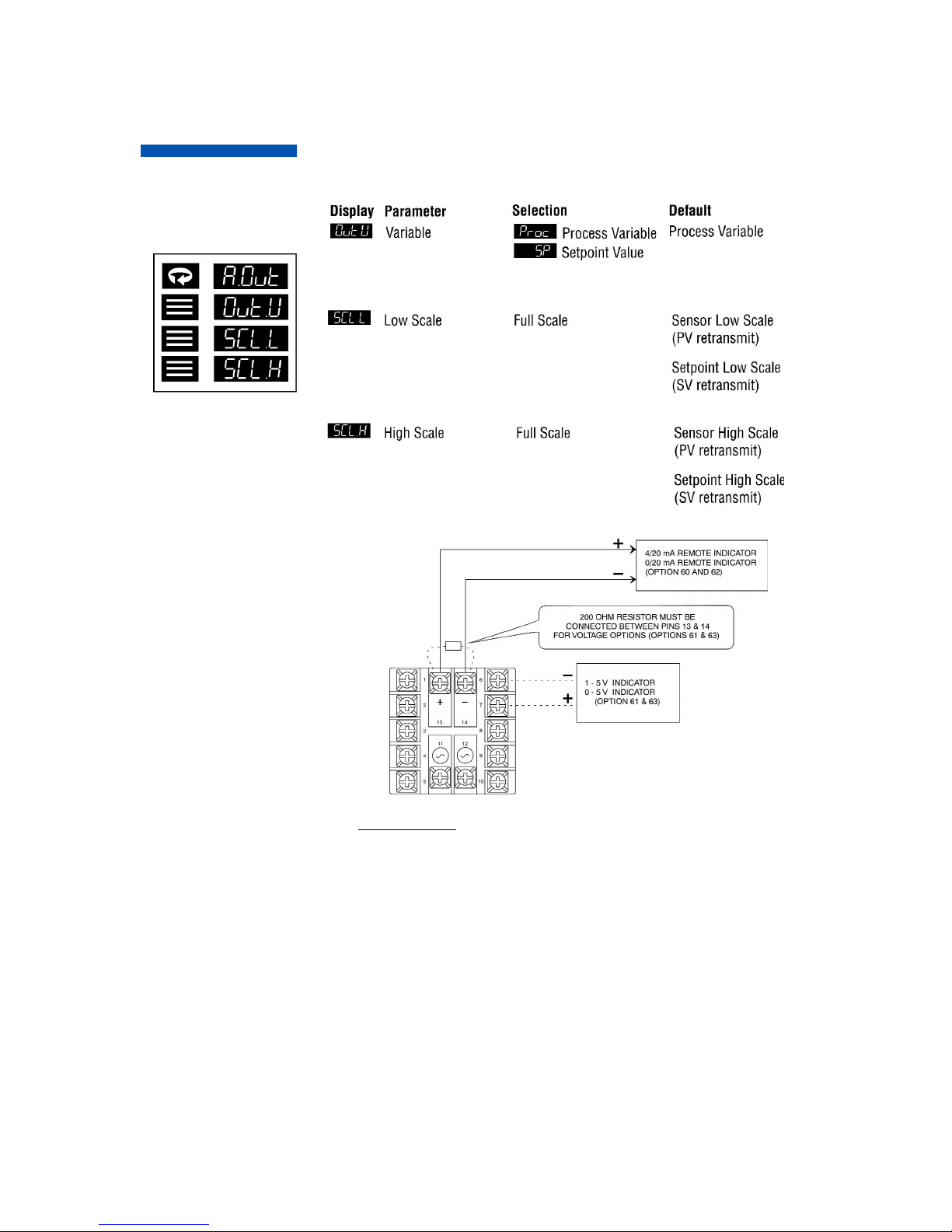
Option #60, #61, #62, #63: Auxiliary Output
Option Description: The Setpoint Variable or Process Variable is
transmitted to a remote device (chart recorders, indicators, data recorders, computers, process
controllers, etc.) with 1 of 4 different interfaces:
Option 60: 4-20 mA
Option 61: 1-5 V
Option 62: 0-20 mA
Option 63: 0-5 V
The output signal is scalable in the Auxiliary Output Menu. Multiple remote indicators
may be driven by the controller. However, current and voltage outputs cannot be used
simultaneously.
For current (mA) options, the remote indicators are connected in series. The sum of
the input resistance for all remote indicators must be less than 400 ohms. For voltage
options, the remote indicators are connected in parallel.
The sum of the currents for all remote indicators must be less than 10 mA.
Page 13

10
Remote Analog
Setpoint
Option #80, #81, #82, #83, #84: Remote Analog
Setpoint
Option Description: Remote setpoints use either voltage or current inputs,
depending on the specified option:
Option 80: 0-5 V
Option 81: 1-5 V
Option 82: 0-20 mA
Option 83: 4-20 mA
Option 84: 0-10 V
The input signal is scalable in the Remote Analog Setpoint Menu. Activation of the
analog setpoint causes the F1 indicator to illuminate. For current (mA) options, the
input resistance is 255 ohms. For voltage input options, the input resistance is greater
than 10K ohms.
*Ground shield at one end, taking care not to run wires next to power circuitry.
Maximum length will be determined by noise performance.
Page 14

11
Series
16C
with
Digital
Communications
Option
Page 15

12
Digital
Communications
Option
Remote Communications Options
RS-232
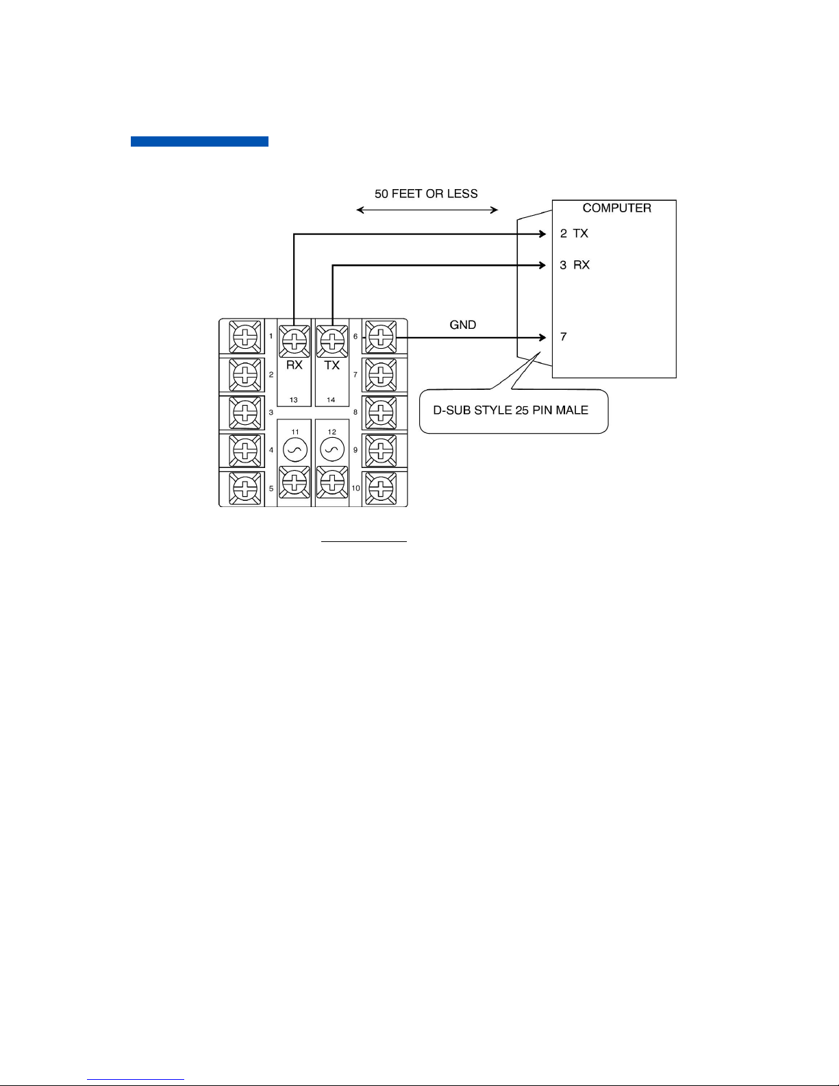
This method allows bidirectional data transfer via a threeconductor cable consisting of signal ground, receive input and
transmit output. It is recommended for communication distances
less than 50 feet between the computer terminal and the instrument. Note: Multiple instruments cannot be connected to the same
port.
The RS232 port is optically isolated to eliminate ground
loop problems. Typically, “Data Out” of the computer/
terminal connects to the “RCV” terminal. “Data In” connects to the
“XMT” terminal. If shielded cable is used, it should be connected to
the frame ground at one end only. Signal ground is to be connected
at appropriate ground terminals (refer to wiring diagram on next
page).
RS-422
This method allows bidirectional data transfer via a fourwire conductor cable for distances over 50 feet between
the computer terminal and the instrument. A signal ground
wire is not required.
RS-485
The RS485 multipoint capability allows up to 32 controllers to be
connected together in a half-duplex network or up to 100 controllers with an appropriate communications repeater.
Three remote communications options are
available for the 16C
which allow interfacing
to remote devices
utilizing the most
common industry
standards: RS232,
RS422, and RS485.
Page 16

13
Digital
Communications
Option
This method allows bidirectional data transfer over a twisted pair cable. The twisted
pair cable is a transmission line; therefore, terminating resistors are required at the
most distant ends of the line to minimize reflections (typically 120 ohms at each end).
The RS485 circuit is fully optically isolated, eliminating ground loop problems. Parallel
drops from the transmission lines should be kept as short as possible; however, the
line may be daisy-chained at each controller. The polarity of the line is important and
each device will specify an “A” (+) and “B” (-) connection.
Figure 1a. Wiring diagram for
RS-232 digital communications.
Figure 1b. Wiring diagram for
RS-485 digital communications.
Note: Call factory for a
recommended RS485
converter.
Page 17
14
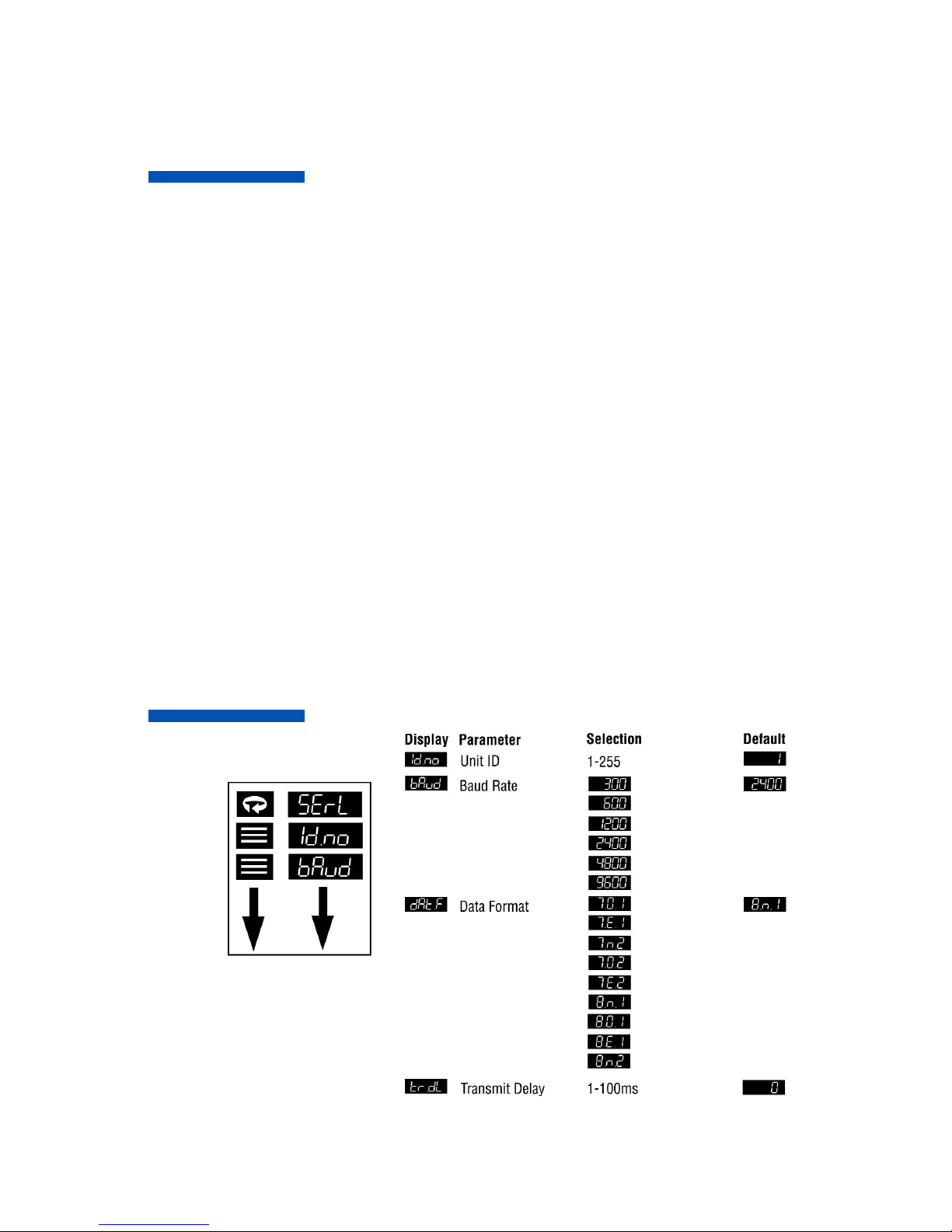
Athena+ Protocol (Standard)
Communications
Option Menu
Athena+ Protocol
The Athena+ Protocol provides an easy way to query and
modify controller parameters using a personal computer and the
optional digital communications option of the 16C.
In this manual, the word “host” refers to the personal computer
that’s communicating with the controllers in the serial link, and the
word “slave” refers to the controllers themselves.
All transactions between the host and the slaves are done with
messages consisting of only printable ASCII characters. There are
only two primary types of messages: Requests
and Responses. Messages coming from the host are called
requests and messages coming from the slaves are called
responses.
With the exception of a broadcast request, for every request sent
from the host, the slave will send back a response. If a slave does
not respond within 100 milliseconds, then the request can be considered lost.
A broadcast request is a request having an ID of ‘00’ (see Message
Formats on next page). It is used to address all slaves on the network. All slaves on the network will perform the actions requested
in a broadcast message. However, a response message will not be
returned. Therefore, the host can only broadcast Write or Auxiliary
Command Requests. All slaves will ignore all Read Broadcast
Requests.
Digital
Communications
Option
Page 18

15
Message Formats
All Athena+ messages adhere to the general format of:
[START CHAR][ID][ZONE][TYPE][PARAM][ERROR]
[DATA][CHKSUM][END CHAR]
START CHAR
This is a single character which designates the start of the message. For a Request message, this character is the ASCII ‘$’ and
for a Response message, this character is the ASCII ‘%’.
ID
This is a two-character ID identifying the receiving controller.
Controller IDs go from 1-255 inclusively and all slaves in the network must have unique IDs. The ID number of ‘00’, when used in a
request, designates a broadcast message that is used to address
all controllers in the network. See the section Request Message for
an explanation of the broadcast message.
In order to represent 255 with just two ASCII characters, a number
system known as the Message Code Numbering System is used.
In this system, the most significant digit is represented with the
numbers 0-9 and the letters A-Z and the least significant digit is
represented with the numbers 0-9. The numbers 0-9 have the
Digital
Communications
Option
Page 19

16
same values as their decimal
counterparts and the letters A-Z have the values of 100 - 350 inclusively in increments of 10.
Example:
Message Code Value = Decimal Value
00 0 + 0 = 00
99 90 + 9 = 99
A0 100 + 0 = 100
A2 100 + 2 = 102
B8 110 + 8 = 118
P5 250 + 5 = 255
Zone
This is a two character ID identifying the Zone number in multizone capable controllers. For the 16C, this number must be 01.
Digital
Communications
Option
Page 20

17
Type
This is a single character identifying the type of message. The following table lists the type characters for all messages.
TYPE character Message Type
R Read Request or Read
Response Returning a
Positive Result
r Read Response Returning a
Negative Result
W Write Positive Value Request
and Response
w Write Negative Value Request
and Response
A Auxiliary Command
For further information, see following sections on the
different message types.
Digital
Communications
Option
Page 21

18
PARAM
This is a two character, message specific, parameter ID. For a
Read/Write Request or Response message, this ID identifies the
controller parameter. For an Auxiliary Command Request or
Response message, this ID specifies the command.
STATUS
This is a single-character field used in all response messages, containing a status code specifying the status of the request message
received.
DATA
This field contains the ASCII representation of the value of the
parameter. For the Auxiliary Request or Response messages, this
field either contains the ASCII representation of a numeric value or
just ASCII data. The length of this field depends on the message
type. The discussion on the specific message types gives the exact
requirements for this field.
All ASCII representations of numeric values must be done using
the characters ‘0’-‘9’, and ‘.’. Any use of other ASCII characters,
including‘ ‘ and ‘-’ will result in a bad message. Negative numbers
CANNOT be represented by preceding the number with ‘-’ character. Instead, a special message type is used. See subsequent sections for more information.
Digital
Communications
Option
Page 22

19
Digital
Communications
Option
IMPORTANT:The data field in the Read and Write Request and
Response messages must and will only contain the
characters ‘0’-’9’, and the decimal point ‘.’. All other characters are
considered illegal. When the data field is listed as Unused or
Ignored in an auxiliary command, it does not mean that the field
can be skipped when sending in the request message. Instead, this
field must be padded with any 10 alphanumeric (only letters and
numbers are allowed) ASCII characters.
Figure 2. Sample Communications Commands
Figure 3. Requesting a Parameter from a Controller
Page 23

20
Examples of valid numeric representations for a
6 character data field:
Numeric Value ASCII Representation
3 3.0000
000003
003.00
100 100.00
0100.0
000100
3.2 003.20
0003.2
Examples of invalid numeric representations for 6 character data
field: (B represents a blank, or a space, character)
Numeric Value Bad ASCII Representation Why?
3 BBBBB3 Leading blanks
are not allowed.
3.0BBBB Trailing blanks
are not allowed.
-3.2 -3.20000 ‘-’ is not
allowed.
Digital
Communications
Option
Page 24

21
CHKSUM
This is a two character Message Code Numbering System, representing the sum of all the ASCII values of all the characters
(excluding the START, CHAR, the END CHAR, and the CHKSM
themselves) in the message. The sum is computed using the following formula:
CHKSM = SUM(All Message Characters)%256
% represents the modulus operator.
END CHAR
This is a single character designating the end of the message. For
all messages, the character used is <CR>, the carriage return.
Request Messages:
Request Messages are sent from the host to the slaves. Each
request will have an ID identifying the intended recipient of the
request. If the ID is ‘00’ (zero), then the request is a broadcast
message. All slaves will perform the action requested in the broadcast request. However, a response message will not be returned.
Therefore, it only makes sense to send Write or Auxiliary
Command Requests as broadcast requests. There are three types
of Request Messages: Read, Write, and Auxiliary Commands.
Digital
Communications
Option
Page 25

22
The Read Request:
The Read Request is used to query parameter values and it has
the following message format:
[START CHAR][ID][ZONE][TYPE][PARAM][CHKSUM][END CHAR]
Field Description: TYPE Must contain the uppercase letter ‘R’.
Request Message Description
$Ø1Ø1RØ5C1<CR> Queries the value of the Process Variable
of Controller #1.
$Ø1Ø1RØ9C5<CR> Queries the value of the EEPROM
Setpoint 1 of Controller #1
$Ø2Ø1RØ9C6<CR> Queries the value of the EEPROM
Setpoint 1 of Controller #2.
END CHAR
CHKSUM
PARAM
TYPE
ZONE
ID
START CHAR
Digital
Communications
Option
Examples of the responses to these requests are given
in later sections on Response Messages.
Page 26

23
The Write Request:
The Write Request is used to modify parameter values and it has
the following message format: [START CHAR][ID][ZONE]
[TYPE][PARAM][DATA][CHKSUM][END CHAR]
Field Description: TYPE This field must contain one of the following
two characters.
W– Value in DATA is a positive value.
w– Value in DATA is a negative value.
DATA A six-character ASCII representation of a
numeric value.
Request Message Description
$Ø1Ø1WØ91Ø.123G7<CR> Change both the RAM and EEPROM
copies of Setpoint #1 in controller #1
to the value of 10.123
$Ø1Ø1w1Ø1Ø.123J1<CR> Change only the RAM copy of
setpoint #1 in controller #1 to
the value of -10.123 (notice the
lowercase ‘w’).
END CHAR
CHKSUM
DATA
PARAM
TYPE
ZONE
ID
START CHAR
Digital
Communications
Option
Page 27

24
Response Messages:
Response Messages are replies to the requests sent from the host.
For each request received, the slave will reply back with
a response.
For all requests, the Athena+ Protocol specifies a maximum
response time of 100 milliseconds. If a response is not received
after 100 milliseconds, that request can be
considered lost.
There are three types of Response Messages: Read, Write,
and Auxiliary Commands.
The Auxiliary Command Request:
The Auxiliary Command Request is used to issue commands to the
controllers and it has the following message format:
Field Description: TYPE This field must contain the uppercase
letter ‘A’
DATA A ten-character ASCII representation of a
numeric value or 10 alphanumeric ASCII characters.
Request Message Description
$Ø1Ø1AØ1XXXXXXXXXXL2<CR> Tell controller #1 to load
all parameters with their
defaults. The 10 X’s are
padding characters.
$Ш2Ш1AШ2ШШШ1.ШШШШШ69<CR> Tell controller #2 to
perform a low RTD
calibration.
END CHAR
CHKSUM
DATA
PARAM
TYPE
ZONE
ID
START CHAR
Digital
Communications
Option
Page 28

25
The Read Response:
The Read Response will be sent in response to a Read Request.
Some examples:
Request Message Description
%Ø1Ø1RØ5Ø21.123K8<CR> The value of the Process
Variable is 21.123 Degrees C.
%Ø2Ø1R1Ø1G7<CR> A serial transmission has
occurred: Framing Error
%Ø1Ø1rØ9Ø21.ØØØN8<CR> The value of the EEPROM
setpoint #1 is -21 Degrees C
(notice the lowercase ‘r’).
END CHAR
CHKSUM
DATA
STATUS
PARAM
TYPE
ZONE
ID
START CHAR
Digital
Communications
Option
Page 29

26
The Auxiliary Command Response:
The Auxiliary Command Response will be sent in response to an
Auxiliary Command Request.
Some examples are:
Request Message Description
%Ø1Ø1AØ1ØXXXXXXXXXXØ4<CR> Default load all para-
meters has started.
%Ш2Ш1AШ2ШШ.ШШШШШШШШB6<CR> RTD low calibration
on controller #2 has
started.
END CHAR
CHKSUM
DATA
STATUS
PARAM
TYPE
ZONE
ID
START CHAR
The Write Response:
The Write Response will be sent in response to a Write Request.
Some examples:
Request Message Description
%Ø1Ø1WØ93I1<CR> A serial transmission error
has occurred: Parity error.
Write failed.
%Ø1Ø1w1ØØK2<CR> RAM copy of setpoint #1
modified successfully.
END CHAR
CHKSUM
STATUS
PARAM
TYPE
ZONE
ID
START CHAR
Digital
Communications
Option
Page 30

27
Digital
Communications
Option
Parameter Parameter
Number Description Number Description
1 Controller Type 19 Manual Control
2 Software Version 2 Percentage
3 Communications 2Ø Output 1 Deadband
Version 21 Output 1 Hysteresis
4 Status Byte 22 Output 1 Proportional
5 Process Value Band
6 Operating Mode 23 Output 2 Proportional
7 Access Level Band
8 Contact/Digital 3Ø Rate/Derivative Action
Input State 32 Reset/Integral Action
9 Setpoint - RAM, 34 Manual Reset/
EEPROM Internal Action
1Ø Setpoint - RAM 37 Output 2 Deadband
Only 38 Output 2 Hysteresis
11 Second Setpoint - 39 Autotune Damping
RAM, EEPROM 4Ø Recipe Option
12 Second Setpoint - 41 Single Setpoint Ramp
RAM Only Time
13 Remote Analog 42 Ramp Time 1
Setpoint 43 Ramp Time 2
14 Recipe Setpoint 44 Ramp Time 3
16 Output 1 Percentage 45 Ramp Time 4
17 Output 2 Percentage 46 Ramp Time 5
18 Manual Control 47 Ramp Time 6
1 Percentage 48 Ramp Time 7
Table 1. Communications Parameter List (Athena+ Protocol)
Page 31

28
Digital
Communications
Option
Table 1. Continued
Parameter Parameter
Number Description Number Description
49 Ramp Time 8 73 Soak Time 8
5Ø Ramp Event 1 74 Soak Event 1
51 Ramp Event 2 75 Soak Event 2
52 Ramp Event 3 76 Soak Event 3
53 Ramp Event 4 77 Soak Event 4
54 Ramp Event 5 78 Soak Event 5
55 Ramp Event 6 79 Soak Event 6
56 Ramp Event 7 8Ø Soak Event 7
57 Ramp Event 8 81 Soak Event 8
58 Soak Level 1 82 Recycle Number
59 Soak Level 2 83 Holdback Band
6Ø Soak Level 3 84 Termination State
61 Soak Level 4 85 Power Resume
62 Soak Level 5 86 Input Bias
63 Soak Level 6 87 Input Low Scale
64 Soak Level 7 88 Input High Scale
65 Soak Level 8 89 Lower Setpoint Limit
66 Soak Time 1 9Ø Upper Setpoint Limit
67 Soak Time 2 91 Input Filter
68 Soak Time 3 92 Input Type
69 Soak Time 4 94 Output 1 Type
7Ø Soak Time 5 95 Output 1 Action
71 Soak Time 6 96 Output 1 Alarm
72 Soak Time 7 Action
Page 32

29
Digital
Communications
Option
Table 1. Continued
Parameter
Number Description
B6 TC/RTD Decimal Position
B7 Linear Decimal Position
B8 Display Filter
B9 Display Units
C1 Display Blanking
C2 Alarm 1 Action
C3 Alarm 1 Operation
C4 Alarm 1 Delay
C5 Alarm 1 Inhibit
C6 Alarm 1 Process Setpoint
C7 Alarm 1 Deviation Setpoint
C8 Alarm 2 Action
C9 Alarm 2 Operation
DØ Alarm 2 Delay
D1 Alarm 2 Inhibit
D2 Alarm 2 Process Setpoint
D3 Alarm 2 Deviation Setpoint
D4 Communication Protocol
D5 Communication ID
D6 Communication Baud Rate
D7 Communication Data Format
D8 Communication
Transmit Delay
E1 Output 1 Failsafe %
E2 Output 2 Failsafe %
Parameter
Number Description
97 Output 1 Alarm Operation
98 Output 1 Alarm Delay
99 Output 1 Alarm Inhibit
AØ Output 1 Process
Alarm Setpoint
A1 Output 1 Deviation
Alarm Setpoint
A2 Output 1 Cycle Time
A3 Output 1 Low Limit
A4 Output 1 High Limit
A5 Output 2 Type
A6 Output 2 Action
A7 Output 2 Alarm
Action N/A
A8 Output 2 Alarm Operation
A9 Output 2 Alarm
Delay N/A
BØ Output 2 Alarm Inhibit
B1 Output 2 Process
Alarm Setpoint
B2 Output 2 Deviation
Alarm Setpoint
B3 Output 2 Cycle Time
B4 Output 2 Low Limit
B5 Output 2 High Limit
Page 33

30
Parameter
Number Description
E3 Loop Break Time
E4 Highest Reading
E5 Lowest Reading
E8 Option Selection N/A
E9 TC Zero Calibration
FØ TC Span Calibration
F1 RTD Zero Calibration
F2 RTD Span Calibration
F3 Low-Voltage Zero
Calibration
F4 Low-Voltage Span
Calibration
F5 High-Voltage Zero
Calibration
F6 High-Voltage Span
Calibration
F7 Current Zero Calibration
F8 Current Span Calibration
G1 Auxiliary Output Variable
G2 Auxiliary Output
Scale Low
G3 Auxiliary Output
Scale High
G5 RAS Scale Low
G6 RAS Scale High
Digital
Communications
Option
Table 1. Continued
Parameter
Number Description
G7 Contact/Digital
Switch Function
H2 Autotune State
H3 Recipe State
H5 Current Recipe
Segment
H6 Active Setpoint
H7 Resume Exhaustion
Flag
F4 Low-Voltage Span
H8 LED Status Indicator
H9 RTD (with decimal
support) Zero Calibration
I
Ø RTD (with decimal
support) Span Calibration
Page 34

31
Auxiliary Commands:
Command: Load Parameter Defaults
Parameter #: 01
Description Restore all menu parameters to their
default values.
Request Data Field: Ignored.
Response Data Field: Ignored.
Command: Perform Process Low Calibration
Parameter #: 02
Description: Performs a Low Calibration. The
data field in the request message
specifies the process. Make sure the
prerequisite for the calibration is
satisfied before issuing a calibration
command. For instance, the RTD
calibration command must only be
used when the input sensor type is
chosen as RTD or RTD w/ Decimal.
Digital
Communications
Option
Page 35

32
Request Data Fields: A 10 character ASCII representation
of a numeric value specifying what
to calibrate.
0 - Thermocouple
1 - RTD, Resistive Thermal Device
2 - Linear
3 - RAS, Remote Analog Setpoint
Response Data Field: Ignored.
Command: Perform Process High Calibration
Parameter #: 03
Description: Performs a High Calibration. The data
field in the request message specifies
the process. Make sure the prerequisite for the calibration is satisfied
before issuing a calibration command
For instance, the RTD calibration
command must only be used when the
input sensor type is chosen as RTD or
RTD w/ Decimal.
Request Data Field: A 10 character ASCII representation
of a numeric value specifying what
to calibrate.
Digital
Communications
Option
Page 36

33
0 - Thermocouple
1 - RTD, Resistive Thermal Device
2 - Linear
3 - RAS, Remote Analog Setpoint
Command: Retrieve Display
Parameter #: 05
Description: Retrieves the string currently dis-
played on the slave’s display. The data
field in the request message specifies
which display and the data field in the
response message contains the string.
Request Data Field: A 10 character ASCII representation
of a numeric value specifying which
display to retrieve data from.
0 - Lower Display
1 - Upper Display
Response Data Field: The ASCII string.
Command: Clear Latched Alarms
Parameter #: 10
Description: Clear all latched alarms.
Request Data Field: Ignored.
Response Data Field: Ignored.
Digital
Communications
Option
Page 37

34
Table 2. Communications Error Codes Returned.
Code Description
0 No error.
1 Framing error.
2 Hardware error.
3 Parity error.
4 Bad character in the TYPE field.
5 Bad message. Message cannot be understood.
6 Bad checksum. The checksum received did not
match the checksum of the message.
7 Bad zone ID.
8 Bad auxiliary command ID. The auxiliary command
is not supported in this controller.
9 Bad parameter ID. The parameter is not supported
in this controller.
A Bad data. Bad representation in the data field or
data is out of range.
B Attempt to write to a read only parameter.
C Cannot write to a parameter because it’s in use.
Digital
Communications
Option
Page 38

35
Communications
Option Menu
Option “ED” – SPI Protocol
Page 39

NOTES
Page 40

For technical assistance, call toll free
1-800-782-6776 (in the U.S.)
or
610-828-2490
(from anywhere in the world),
or
e-mail: techsupport@athenacontrols.com.
Athena Controls, Inc.
5145 Campus Drive
Plymouth Meeting, PA 19462 USA
Toll-free: 800.782.6776
Tel: 610.828.2490
Fax: 610.828.7084
techsupport@athenacontrols.com
athenacontrols.com
900M012U00 REV “C” - 05022005
 Loading...